

Page 1

IEEE 8
02.11ac/a/
b/g/n
WLAN
This manual may not be copied in any media or form without the written consent of original maker.
and BT Combo Adapter
LM813
USER’S GUIDE
VERSION 1.1
© All rights reserved.
All trade names are registered trademarks of respective manufacturers listed.
Page 2

1. Introduction .........................................................……...... 1
2. Wireless LAN Basics ................................................……...... 3
3. IP ADDRESS ..........................................................………….. 4
4. Install Driver/Utility ...............................................………….. 5
4.1 Windows 7/8.1/10............................................... ...... 5
5. Wireless/Bluetooth Network Configuration ................................ 7
5.1 Utility Icon .............................................................. 7
5.2 Client Mode (Default Setting)........................................ 7
5.3 Virtual WiFi ............................................................ 13
5.4 Access Point ............................................................ 14
5.5 Bluetooth Setup........................................................ 16
6. Technical Specifications ................................................ . .. 18
7. Troubleshooting .............................................................. 20
8. Glossary ....................................................................... 21
Page 3

1
Thank you for your purchase of the WLAN and Bluetooth dual mode
Adapter. Featuring wireless technology, this wireless networking solution
has been designed for both large and small businesses, and it is scalable
so that you can easily add more users and new network features
depending on your business scale.
FEATURES
Support Microsoft 7 / 8.1 / 10 (32bit/64bit)
Operating distance of up to 300 meters in free space.
433.3/300/270/240/180/120/90/60/54/48/36/30/24/22/18/12/11/6/5.5/2/
1 Mbps selectable Data Rate according to client adapter default
antennas.
64/128-bit WEP , WPA, WPA2, WPS
2.400GHz ~ 2.4835GHz unlicensed ISM Frequency Band. Modulation
Method. 5GHz UNII, Midband, ISM bands.
IEEE 802.11b : DSSS (Direct Sequence Spread Spectrum).
IEEE 802.11 ac/a/g/n : OFDM (Orthogonal Frequency Division
Multiplexing).
Easy operation and setting up.
Bluetooth 2.1 / 4.2 dual mode integrated with Microsoft Windows
Bluetooth features.
SYSTEM REQUIREMENTS
Windows System : 7 / 8.1 / 10 (32bit/64bit).PCs must have a device driver
installed. It allows you to communicate with WLAN 11ac USB Client
Adapter.
Page 4

2
BEFORE YOU START
1. Confirm Box Contents
WLAN 11ac USB Client Adapter
Quick Start Guide
Driver CD
CONNECTING YOUR WLAN 11ac USB CLIENT ADAPTER TO PC
Quick Start Guide
Connect your WLAN 11ac USB Client Adapter to your PC. Install driver.
GETTING TO KNOW WIRELESS LAN ADAPTER
LED Status
Quick Blinking – Adapter connects to Access Point.
Steady Blinking – Adapter is active.
Off – Adapter is disabled.
Best Performance Requirement
1T1R ac Adapter
USB 2.0
Windows 7 or above
Wireless utility installed
Wireless 802.11ac AC1750 AP/Router with gigabit Ethernet port
Page 5
3
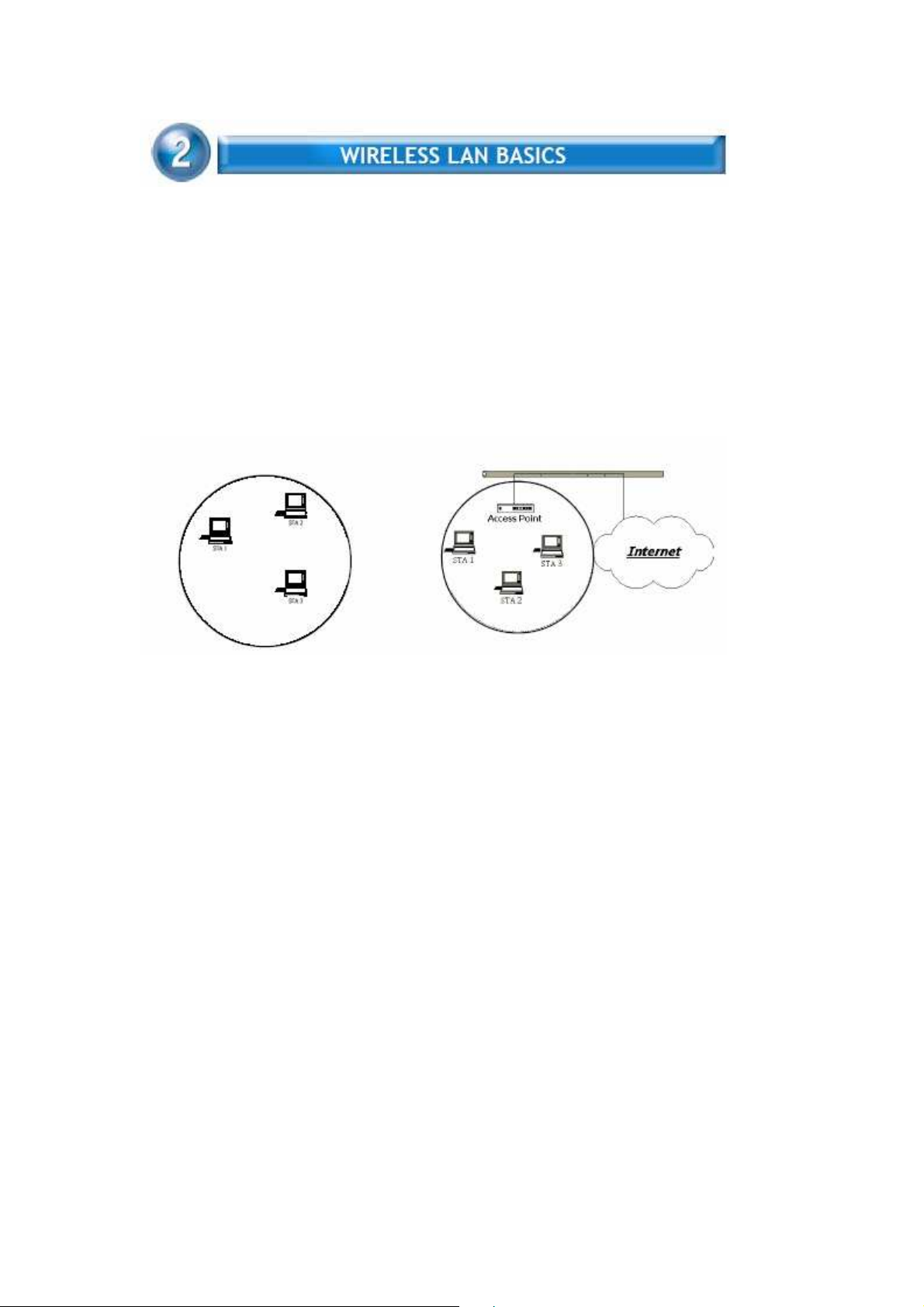
Wireless LAN network defined by IEEE 802.11ac/a/b/g standard committee
Could be configured as:
Ad Hoc wireless LAN – (Win10 is not available)
Infrastructure wireless LAN.
Ad Hoc network is a group of PCs installed with wireless LAN cards; this group
of PCs is called a BSS (Basic Service Set). PCs in this group can use their
wireless LAN cards to communicate with each other, but can not connect to the
Internet.
Ad Hoc Wireless Network Infrastructure Wireless Network
The most obvious difference between Infrastructure wireless network and Ad
Hoc wireless network is that the PCs in Infrastructure wireless network can
access the resource in the Internet through Access Point.
Depending on your requirement, you can easily set up your PC’s network to be
a “Ad Hoc” or “Infrastructure” wireless network. Generally speaking, if in your
network, there is an Access Point in it, we recommend you to set your
network as an “Infrastructure”, so it can connect to the Internet.
Page 6

4
To use the WLAN 11ac USB Client Adapter with a computing device, the
WLAN and Bluetooth Combo Adapter must be equipped with a proper Interface.
All drivers and supporting software for the WLAN Adapter must be installed and
configured first.
Ask your system administrator for the following information, which
you may need to provide during driver installation :
Your Wireless Client Name.
Your Wireless SSID.
Your computer’s unique client name and workgroup name. For your
network account, your user name and password.
Your IP address, gateway address, and subnet mask if you’re not
using a DHCP client.
Any computer on a network is identified by a unique network address. There
are two methods to assign a network address to a computer on a TCP/IP
network :
Static IP addressing.
Dynamic IP addressing (DHCP Client).
In network with static IP addressing, the network administrator manually
assigns an IP address to each computer. Once a static IP address is assigned,
a computer uses the same IP address every time it reboots and logs on to the
network. You may manually change the IP address in the
dialog box.
Network using static IP address is easy to set up and do not
Network Properties
require additional network management software.
In network with dynamic IP addressing, a DHCP server in the network
dynamically assigns IP addresses to all clients every time they log on to the
network. Network using dynamic IP address requires setting up and running a
DHCP Server.
Page 7
5
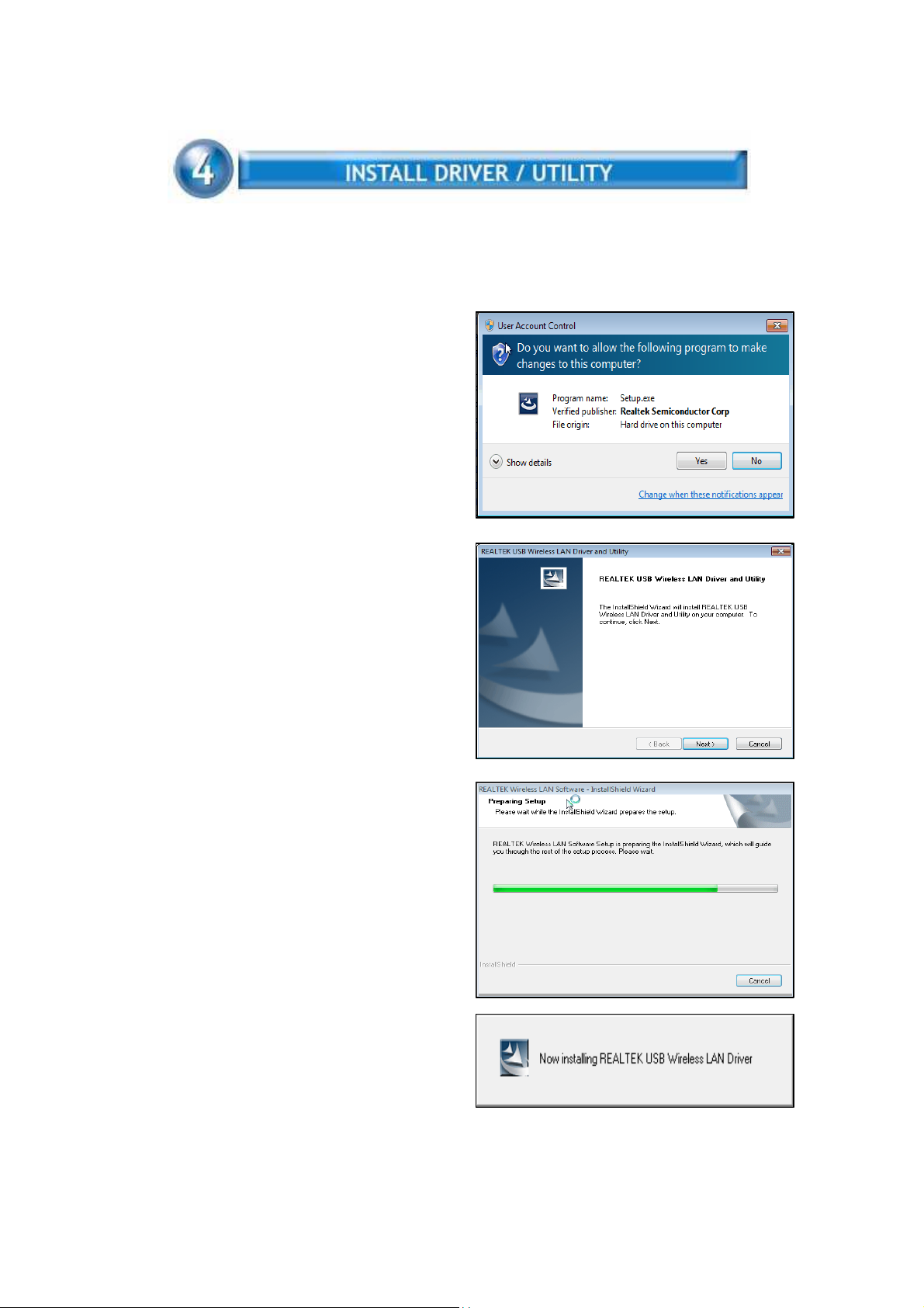
The installation & driver CD will automatically activate the autorun installation
program after you insert the disk into your CD drive.
Step 1 : (Win7/8.1/10 only)
Insert the installation CD into your CDROM. Win7/8.1/10 UAC Dialog is
shown. Click Yes to continue.
Step 2 :
Wizard is ready to install driver and
utility. Click Next to begin the
installation
Step 3 :
Preparing Setup dialog is shown
Installing & configuring WLAN driver
and utility
Page 8

6
Installing Cisco 802.1x module
Step 4 :
Click Finish to complete installation. The installation will affect after windows
rebooting
Page 9
7
WLAN 11ac USB Client Adapter uses its own management software. All
functions controlled by users are provided by this application. When you insert
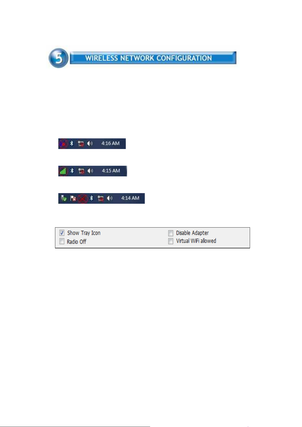
the WLAN Adapter into your laptop or desktop, a icon should appear in the
Windows System Tray automatically.
5.1 Utility Icon
▓
Client mode utility running but no WLAN Adapter plugged
▓
Client mode utility running and WLAN Adapter scan available network.
▓
Client mode utility running and WLAN Adapter can not scan any AP
5.2 Client Mode (Default Setting)
Wireless Device Control :
▓
Show Tray Icon – Show icon or not show icon in system tray.
▓
Radio Off – To stop wireless signal.
▓
Disable Adapter – To stop wireless device.
▓
Virtual WiFi allowed – To enable Soft AP
Page 10
8
5.2.1 GENERAL SETTING
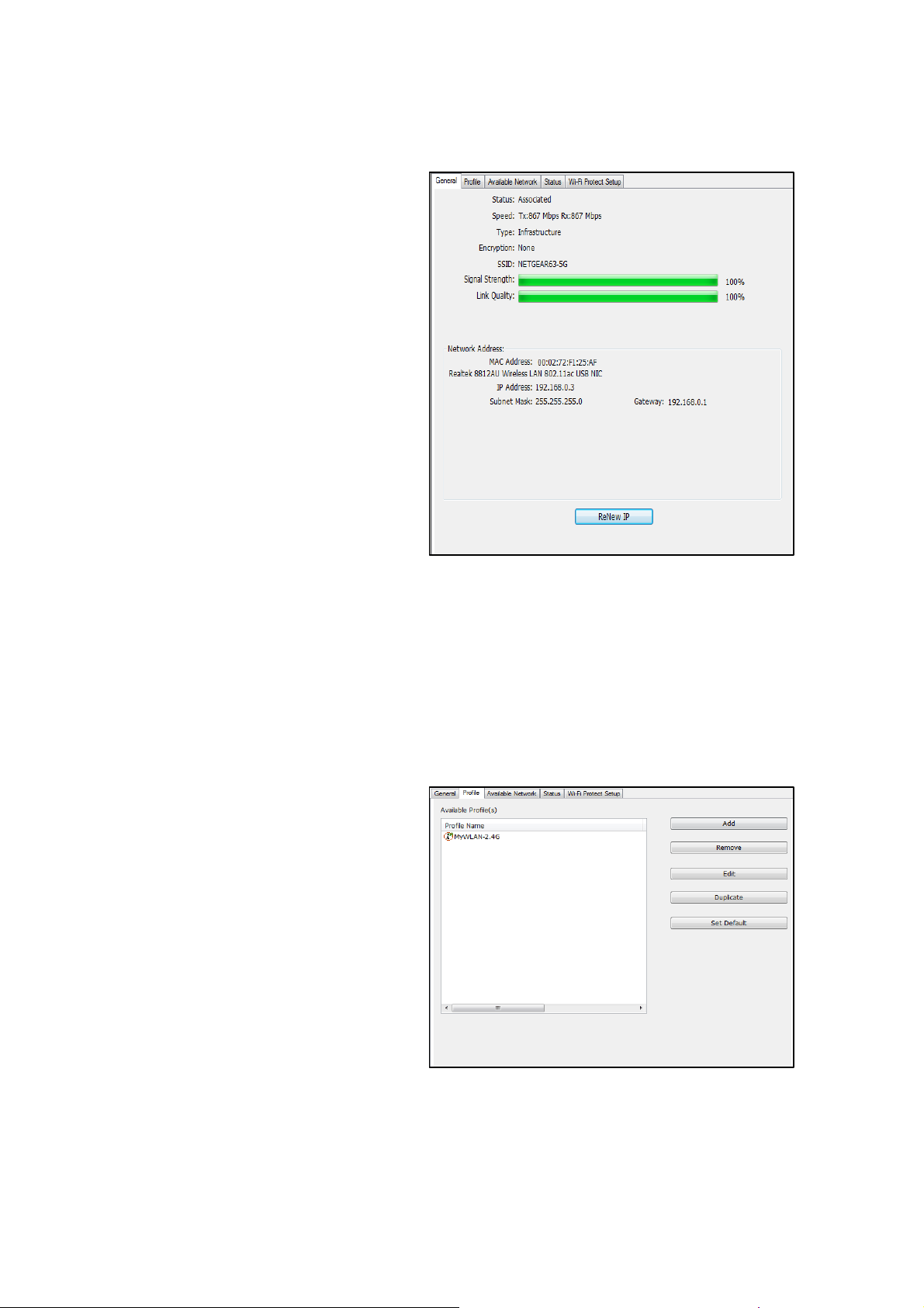
Once device is set,
double click on that
icon and the
configuration window
will pop up as shown. It
shows the current
connected network.
The signal strength and
link quality are
displayed also.
The bar graph displays
the quality and strength
of the link between the
node and its Access
Point. Link Quality is a measurement of receiving and transmitting
performances over the radio.
Network Address displays current MAC Address, IP Address,
Subnet. and Gateway.
Click Renew IP button to refresh IP address leased from wireless
AP.
5.2.2 PROFILE SETTING
In profile tab, you can
Add, Remove, Edit,
Duplicate and Set
Default to manipulate
profile content
manually. Strongly
recommend to use
profile after you do
Available Network.
Page 11
9
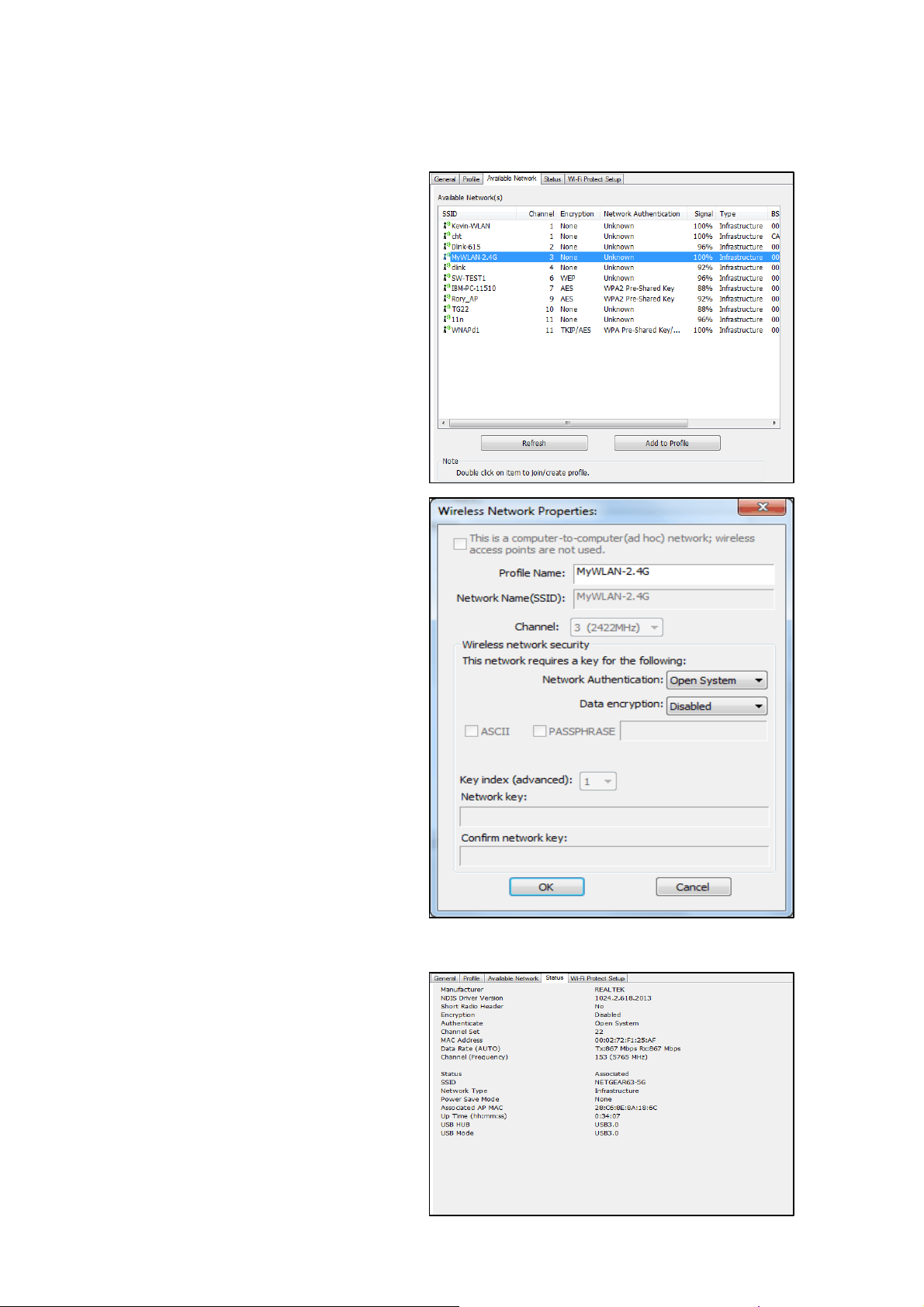
5.2.3 AVAILABLE NETWOEK SETTING
Click Available
Network tab and it will
show all available
networks that radio can
reaches. Select proper
SSID & BSSID you
want to connect.
Click Refresh button to
force and rescan
available
networks currently.
Select one of SSIDs,
and click Add to
Profile to create profile
that
can be configured
more wireless
parameters.
In this page, you can
edit your profile name,
configure wireless
security like WEP,
WPA, WPA2,
802.1x …etc. After
finishing setup, click
OK button to save
configuration
5.2.4 Status
Dialog shows
Manufacture, NDIS
Driver Version, Short
Radio Header,
Encryption,
Authentication,
Channel Set, Mac
Address... etc
information
Page 12
10
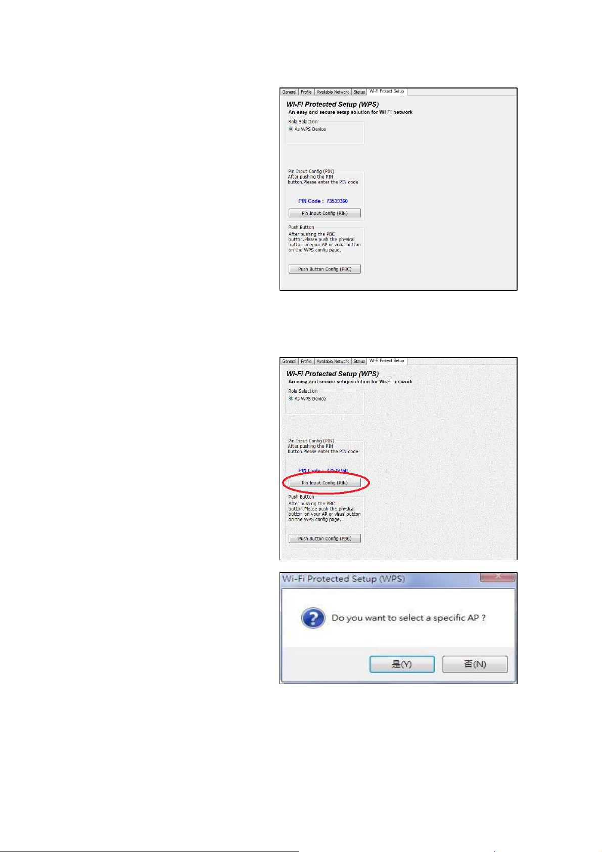
5.2.5 Wi-Fi Protected Setup
An easy and secure
setup solution for Wi-Fi
network. you can
choose PIN Code or
Push Button method to
connect to an AP.
▓
Pin method:
Step 1 :
Press “Pin Input Config
(PIN)” button.
Step 2 :
Select a specific AP
Page 13
11
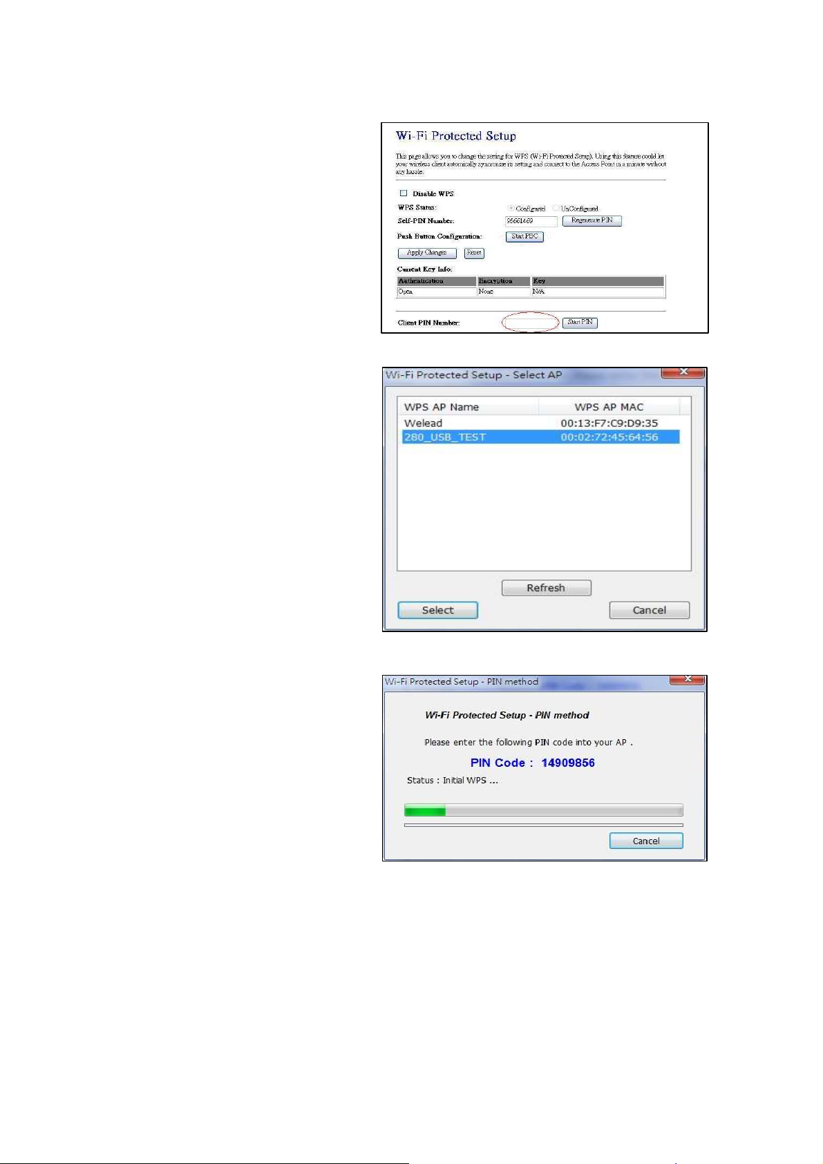
Step 3 :
Enter the PIN code
into your AP.
Step 4 :
Select AP that you
want to configure.
Step 5:
Wait for configuring
your wireless AP to be
the security setting.
Page 14
12
▓
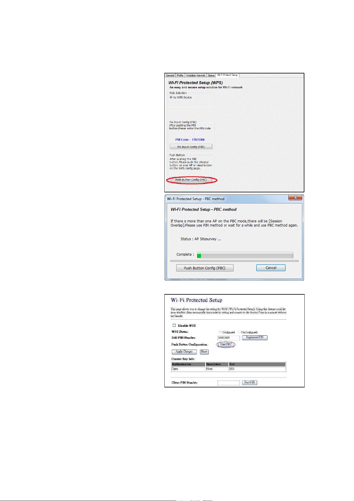
PBC method:
Step 1 :
Press “Push Button
Config (PBC)” button
Step 2 :
Push the physical
button on our AP or
visual button on he
WPS configuration page.
Page 15
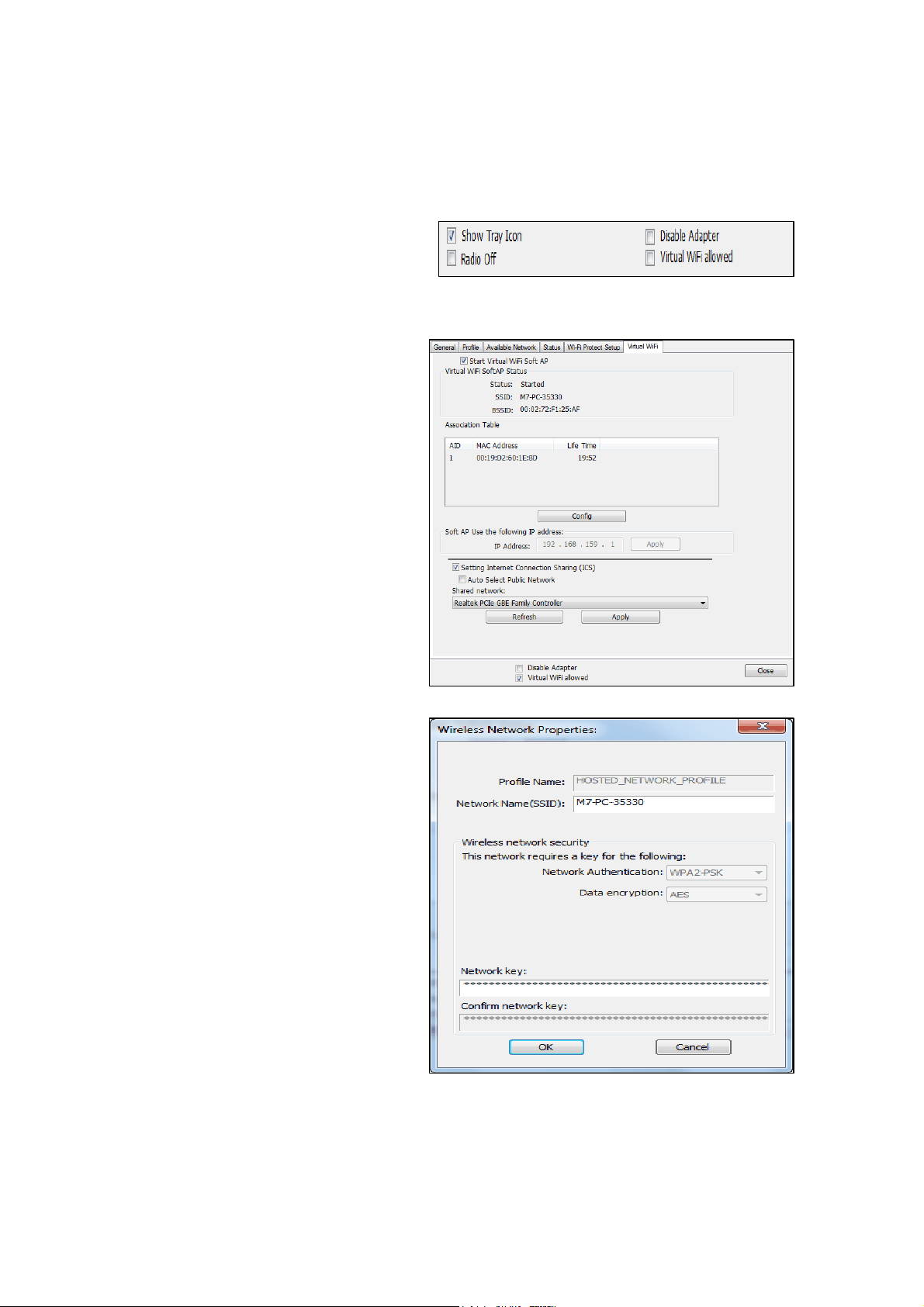
13
5.3 Virtual WiFi Setup
(Use WiFi HotSpot feature under Windows 10 RS or later)
Step 1 :
Click “Virtual WiFi
allowed” option to
enable Virtual WiFi
configuration / status
page.
Step 2 :
Click “Start Virtual
WiFI Soft AP” option to
start
Step 3 :
Click “Config” button
to configure Soft AP
SSID and Security Key.
Step 4 :
To check “Setting Internet Connection Sharing” and “Auto Select
Public Network” options to enable ICS. If setup up Shared Network
manually, press “
Apply” button to re-initialization ICS.
Page 16
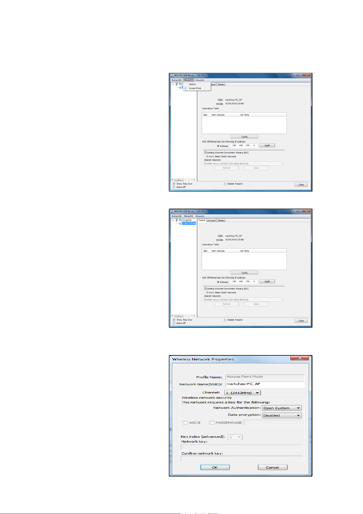
14
5.4 Access Point Mode
(Applied to Windows 8.1 or Windows 7)
Step 1 :
Click “Access Point”
option to enable
proprietary soft AP
configuration / status
page in drop down
menu of Mode(M).
Step 2 :
“General” tab to
show/set up soft AP
status / configuration
like connected wifi
clients info / set
wireless SSID and
security with “Config”
button is clicked or ip
address and internet
connection sharing via
wired connection. Click
“Apply” button after
the ip address is be set.
Step 2.1 :
“Config” is to set up
wireless SSID, available
channel and
authentication /
encryption keys
settings. Click
“OK”/”Cancel” to
save/abort settings
Page 17
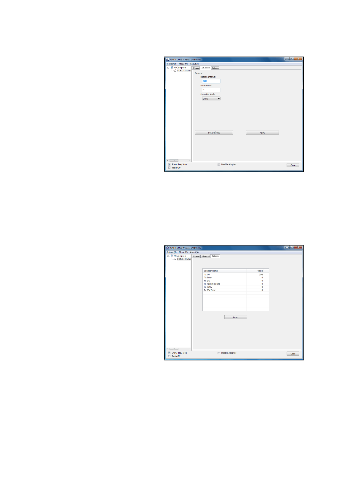
15
Step 3 :
“Advanced” tab to set
up soft AP advanced
configuration like
Beacon Interval, DTIM
Period and Preamble
Mode. Keep default
value if user does not
understand its meaning.
Click “Set Defaults” /
“Apply” to save
factory / custom
settings.
Step 4 :
“Statistics” tab to
show Tx/Rx relative
data of soft AP. Click
“Reset” to reset Tx /
Rx counters
Page 18
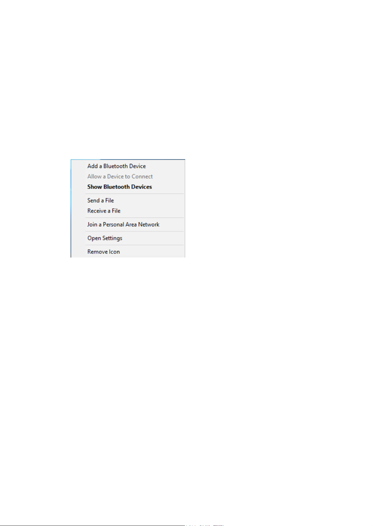
16
5.5 Bluetooth Setup
NOTE:
1.
Show Bluetooth Devices
2.
Add a device
•
•
Windows 7 setup
Add a Bluetooth Enabled Device
To add a Bluetooth enabled device to your computer, you can use the Bluetooth
icon located in the taskbar notification area or you can use a menu item in the
Bluetooth Devices control panel.
Before a Bluetooth device can be found, it must be within range and set to
be discoverable. For information about how to set a particular device to be
discoverable, check the user guide that came with the device.
To add a device using the Bluetooth icon:
Click the Bluetooth icon, click Add a device, and follow the onscreen instructions.
The Add a device wizard handles the pairing process.
To add a device using the Bluetooth Devices control panel:
Double-click the Bluetooth icon, and then click
Click
and follow the onscreen instructions. The Add a
.
device wizard handles the pairing process.
NOTE:
The setup process for a Bluetooth wireless keyboard involves pairing with
your computer.
To conserve battery power, the Bluetooth wireless mouse, keyboard, or
game controller goes to sleep after a specified period of inactivity. To
wake up the mouse or game controller, move it around or click any of the
controls. To wake up the keyboard, press any key.
After you have added a Bluetooth device to your computer, you can begin using
the device.
To remove the device from your computer:
In Bluetooth Devices, select the device and click Remove device.
Page 19
17
Windows 10 Setting
Use Bluetooth to facilitate wireless data transfers with other Bluetooth-enabled
devices.
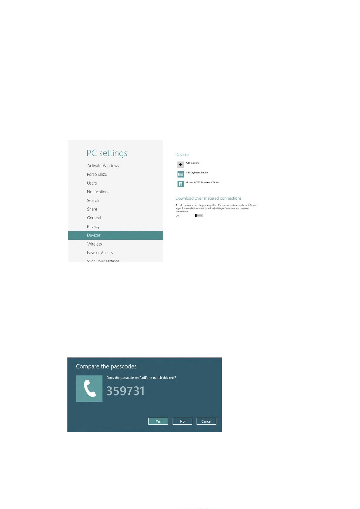
Pairing with other Bluetooth-enabled devices
You need to pair your Notebook PC with other Bluetooth-enabled devices to
enable data transfers. To do this, use your touchpad as follows:
1 Launch the Charms bar.
2 Tap then tap Change PC Settings.
3 Under PC Settings, select Devices then tap Add a Device to search for
Bluetooth-enabled devices.
4 Select a device from the list. Compare the passcode on your Notebook PC
with the passcode sent to your chosen device. If they are the same, tap yes
to successfully pair your Notebook PC with the device.
NOTE: For some Bluetooth-enabled devices, you may be prompted to key in the
passcode of your Notebook PC.
Page 20
18
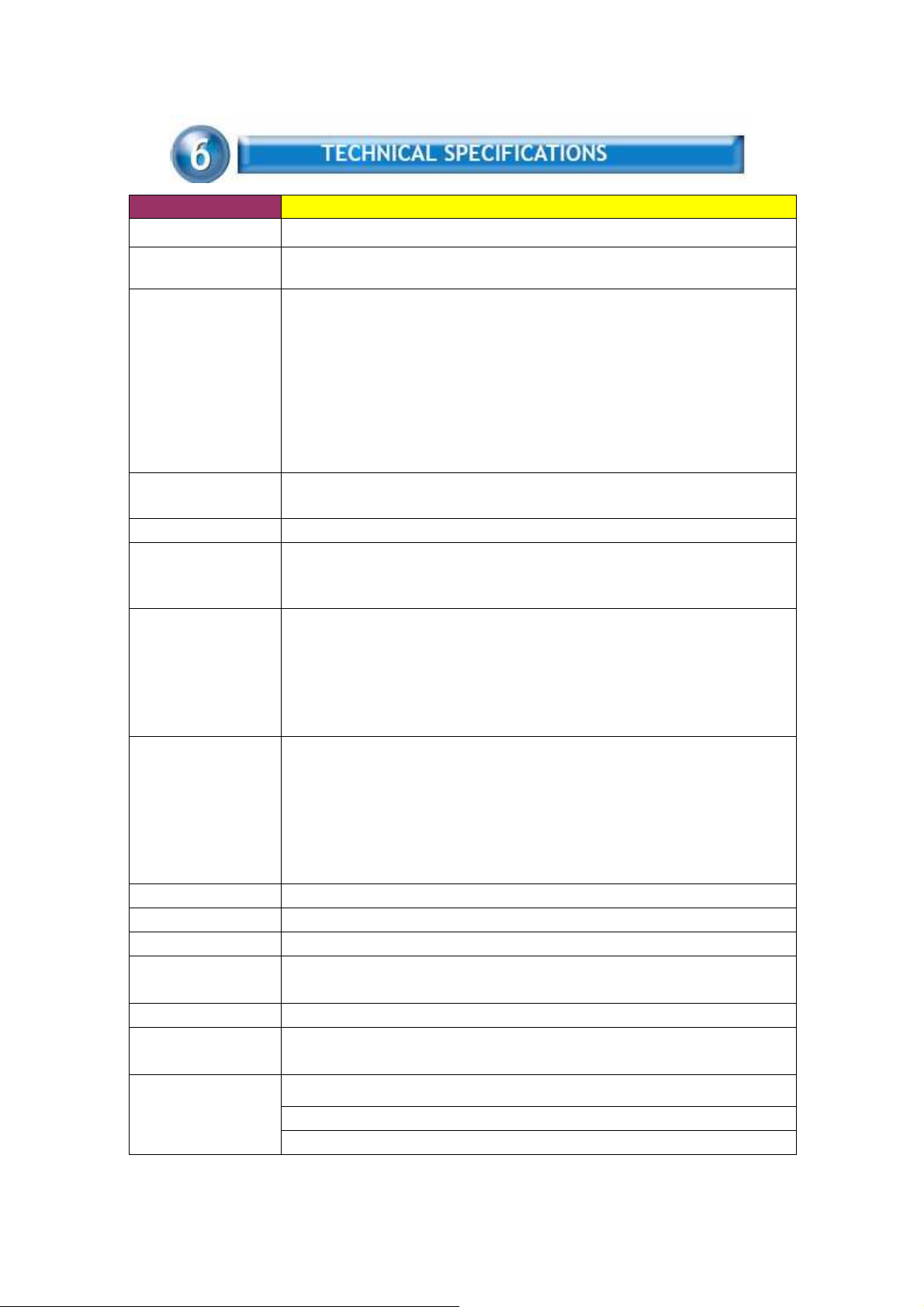
Model Name CL-8821CU
Product Name ac1x1+BT(Disabled) Dongle
Standard
Data Transfer Rate
Modulation Method
Frequency Band 2.4GHz and 5GHz ISM Band
Spread Spectrum
RF Output Power
(tolerance ± 2dBm)
Receiver Sensitivity
Antenna
Security
Power supply
IEEE 802.11b/g/n/a/ac/ e/ h/ i/
Bluetooth v2.1+EDR/ v3.0/ v3.0+HS/ v4.2
WLAN:
802.11b: 11, 5.5, 2, 1 Mbps
802.11g: 54, 48, 36, 24, 18, 12, 9, 6 Mbps
802.11n: MCS0 to 7 for HT20MHz, MCS0 to 7 for HT40MHz
802.11ac: MCS0 to 8 for HT20MHz, MCS0 to 9 for HT40MHz, NSS1 MCS0 to 9
for VHT80MH
Bluetooth:
Basic rate: 1Mbps
Enhanced data rate: 2, 3 Mbps
High Speed: 6, 9, 12, 18, 24, 36, 48, 54 Mbps
WLAN: CCK, DQPSK, DBPSK, BPSK, QPSK,16QAM, 64QAM, 256QAM
Bluetooth: 8DPSK, π/4 DQPSK, GFSKFSK
IEEE 802.11b: CCK (Complementary Code Keying)
IEEE 802.11g/n/a/ac:OFDM
Bluetooth: FHSS (Frequency Hopping Spread Spectrum)
WLAN:
17dBm – 802.11b@CCK 11Mbps
15dBm – 802.11g@OFDM 54Mbps
13dBm – 802.11n@MCS7_HT20
13dBm – 802.11n@MCS7_HT40
13dBm – 802.11a@OFDM 54Mbps
9dBm – 802.11ac@NSS1 MCS9_BW20, BW40, BW80
WLAN:
-80dBm – 802.11b@11Mbps
-70dBm – 802.11g@54MBps
-65dBm – 802.11n@MCS7_BW20
-64dBm – 802.11n@MCS7_BW40
-57dBm – 802.11ac@NSS1_MCS9_BW20
-54dBm – 802.11ac@NSS1_MCS9_BW40
-51dBm – 802.11ac@NSS1_MCS9_BW80
PIFA Antenna x1
WPA, WPA2
USB / 5V
(Orthogonal Frequency Division Multiplexing)
Operating Temperature 0 – 50° C ambient temperature
Storage Temperature -10 ~ 70°C ambient temperature
Humidity 5 to 90 % maximum (non-condensing)
Dimension Housing : 47.9 x 18 x7.55mm (L x W x T)
PCB VC: 25x12.1x0.8mm (L x W x T)
PCB VD: 27x12.1x0.8mm (L x W x T)
The specification is subject to change without further notice
Page 21

19
The channel identifiers, channel center frequencies, and regulatory domains
of each 22-MHz-wide channel are shown in following Table.
Channel
Identifier
1
2
3
4
5
6
7
8
9
10
11
12
13
14
Frequency
(MHZ)
2412
2417
2422
2427
2432
2437
2442
2447
2452
2457
2462
2467
2472
2484
North
Japan
ETSI
● ● ●
● ● ●
America
● ● ● ●
● ● ● ●
● ● ● ●
● ● ● ●
● ● ● ●
● ● ● ●
● ● ● ●
● ● ●
● ● ●
● ●
● ●
●
Israel Mexico
●
●
5GHz Bands descriptions as below
Freq. Bands Frequency
5 GHz UNII1 5.15 -5.25 GHz
UNII2 5.25 -5.35 GHz
Midband 5.47 -5.725 GHz
UNII3 5.725 -5.805 GHz
ISM 5.725 -5.850 GHz
DSRC 5.850 -5.925 GHz
Japan 11j and US public
safety
4.90 -5.1 GHz
Page 22

20
Symptom :
The LED is off.
Remedy :
Make sure the PC Card is inserted properly. Otherwise contact your vendor.
Symptom :
The LED is always on not blinking.
Remedy :
Make sure that you have installed the driver from attached CD. Otherwise
contact your vendor.
Symptom :
The LED is blinking but the PC Card icon does not appear in your icon tray.
Remedy :
Make sure that you have installed the Utility from the attached CD.
Symptom :
The PC Card is linking, but can’t share files with others.
Remedy :
Make sure the file and printer sharing function is enabled. You can
enable the function by checking the icon of My Computer -> Control
Panel -> Network -> file and printer sharing -> I want to be able to give
others to access to my files.
Symptom :
Slow or poor performance under AP mode
Remedy :
Try to select another channel for the communicating group or move your
device closer to the Access Point.
Page 23

21
IEEE 802.11 Standard
The IEEE 802.11 Wireless LAN standards subcommittee, which is formulating
a standard for the industry.
Access Point
An internetworking device that seamlessly connects wired and wireless
networks together.
Ad Hoc
An Ad Hoc wireless LAN is a group of computers, each with a WLAN
adapter, connected as an independent wireless LAN. Ad Hoc wireless LAN
is applicable at a departmental scale for a branch or SOHO operation.
BSSID
A specific Ad Hoc LAN is called a Basic Service Set (BSS). Computers in a
BSS must be configured with the same BSSID.
DHCP
Dynamic Host Configuration Protocol - a method in which IP addresses are
assigned by server dynamically to clients on the network. DHCP is used for
Dynamic IP Addressing and requires a dedicated DHCP server on the
network.
Direct Sequence Spread Spectrum
This is the method the wireless cards use to transmit data over the frequency
spectrum. The other method is frequency hopping. Direct sequence
spreads the data over one frequency range (channel) while frequency
hopping jumps from one narrow frequency band to another many
times per second.
ESSID
An Infrastructure configuration could also support roaming capability for
mobile workers. More than one BSS can be configured as an Extended
Service Set (ESS). Users within an ESS could roam freely between BSSs
while served as a continuous connection to the network wireless stations
and Access Points within an ESS must be configured with the same ESSID
and the same radio channel.
Ethernet
Ethernet is a 10/100Mbps network that runs over dedicated home/office
wiring. Users must be wired to the network at all times to gain access.
Gateway
A gateway is a hardware and software device that connects two dissimilar
Page 24

22
systems, such as a LAN and a mainframe. In Internet terminology, a gateway
is another name for a router. Generally a gateway is used as a funnel
for all traffic to the Internet.
IEEE
Institute of Electrical and Electronics Engineers
Infrastructure
An integrated wireless and wired LAN is called an Infrastructure
configuration. Infrastructure is applicable to enterprise scale for wireless
access to central database, or wireless application for mobile workers.
ISM Band
The FCC and their counterparts outside of the U.S. have set aside bandwidth
for unlicensed use in the so-called ISM (Industrial, Scientific and
Medical) band. Spectrum in the vicinity of 2.4 GHz, in particular, is being
made available worldwide. This presents a truly revolutionary opportunity
to place convenient high-speed wireless capabilities in the hands of users
around the globe.
Local Area Network (LAN)
A LAN is a group of computers, each equipped with the appropriate network
adapter card connected by cable/air, that share applications, data,
and peripherals. All connections are made via cable or wireless media,
but a LAN does not use telephone services. It typically spans a single
building or campus.
Network
A network is a system of computers that is connected. Data, files, and
messages can be transmitted over this network. Networks may be local or
wide area networks.
Protocol
A protocol is a standardized set of rules that specify how a conversation
is to take place, including the format, timing, sequencing and/ or error
checking.
SSID
A Network ID unique to a network. Only clients and Access Points that
share the same SSID are able to communicate with each other. This string
is case-sensitive.
Static IP Addressing
A method of assigning IP addresses to clients on the network. In networks
with Static IP address, the network administrator manually assigns an IP
address to each computer. Once a Static IP address is assigned, a computer
Page 25

23
uses the same IP address every time it reboots and logs on to the
network, unless it is manually changed.
Temporal Key Integrity Protocol (TKIP)
The Temporal Key Integrity Protocol, pronounced tee-kip, is part of the
IEEE 802.11i encryption standard for wireless LANs. TKIP is the next
generation of WEP, the Wired Equivalency Protocol, which is used to
secure 802.11 wireless LANs. TKIP provides per-packet key mixing, a
message integrity check and a re-keying mechanism, thus fixing the
flaws of WEP.
Transmission Control Protocol / Internet Protocol (TCP/IP)
TCP/IP is the protocol suite developed by the Advanced Research
Projects Agency (ARPA). It is widely used in corporate Internet works,
because of its superior design for WANs. TCP governs how packet is
sequenced for transmission the network. The term “TCP/IP” is often
used generically to refer to the entire suite of related protocols.
Transmit / Receive
The wireless throughput in Bytes per second averaged over two seconds.
Wi-Fi Alliance
The Wi-Fi Alliance is a nonprofit international association formed in 1999
to certify interoperability of wireless Local Area Network products based
on IEEE 802.11 specification. The goal of the Wi-Fi Alliance’s members is
to enhance the user experience through product interoperability. The
organization is formerly known as WECA.
Wi-Fi Protected Access (WPA)
The Wi-Fi Alliance put together WPA as a data encryption method for
802.11 wireless LANs. WPA is an industry-supported, pre-standard version
of 802.11i utilizing the Temporal Key Integrity Protocol (TKIP),
which fixes the problems of WEP, including using dynamic keys.
Wide Area Network (WAN)
A WAN consists of multiple LANs that are tied together via telephone
services and / or fiber optic cabling. WANs may span a city, a state, a
country, or even the world.
Wired Equivalent Privacy (WEP)
Now widely recognized as flawed, WEP was a data encryption method
used to protect the transmission between 802.11 wireless clients and
APs. However, it used the same key among all communicating devices.
WEP’s problems are well-known, including an insufficient key length and
no automated method for distributing the keys. WEP can be easily
Page 26

24
cracked in a couple of hours with off-the-shelf tools.
Wireless LAN (WLAN)
A wireless LAN does not use cable to transmit signals, but rather uses
radio or infrared to transmit packets through the air. Radio Frequency
(RF) and infrared are the commonly used types of wireless transmission.
Most wireless LANs use spread spectrum technology. It offers limited
bandwidth, usually under 11Mbps, and users share the bandwidth with
other devices in the spectrum; however, users can operate a spread
spectrum device without licensing from the Federal Communications
Commission (FCC).
Fragment Threshold
The proposed protocol uses the frame fragmentation mechanism defined in
IEEE 802.11 to achieve parallel transmissions. A large data frame is
fragmented into several fragments each of size equal to fragment threshold.
By tuning the fragment threshold value, we can get varying fragment sizes.
The determination of an efficient fragment threshold is an important issue in
this scheme. If the fragment threshold is small, the overlap part of the master
and parallel transmissions is large. This means the spatial reuse ratio of
parallel transmissions is high. In contrast, with a large fragment threshold, the
overlap is small and the spatial reuse ratio is low. However high fragment
threshold leads to low fragment overhead. Hence there is a trade-off between
spatial re-use and fragment overhead.
Fragment threshold is the maximum packet size used for fragmentation.
Packets larger than the size programmed in this field will be fragmented If you
find that your corrupted packets or asymmetric packet reception (all send
packets, for example). You may want to try lowering your fragmentation
threshold. This will cause packets to be broken into smaller fragments. These
small fragments, if corrupted, can be resent faster than a larger fragment.
Fragmentation increases overhead, so you'll want to keep this value as close
to the maximum value as possible.
RTS (Request To Send) Threshold
The RTS threshold is the packet size at which packet transmission is governed
by the RTS/CTS transaction. The IEEE 802.11-1997 standard allows for short
packets to be transmitted without RTS/CTS transactions. Each station can
have a different RTS threshold. RTS/CTS is used when the data packet size
exceeds the defined RTS threshold. With the CSMA/CA transmission
Page 27

25
mechanism, the transmitting station sends out an RTS packet to the receiving
station, and waits for the receiving station to send back a CTS (Clear to Send)
packet before sending the actual packet data. This setting is useful for
networks with many clients. With many clients, and a high network load, there
will be many more collisions. By lowering the RTS threshold, there may be
fewer collisions, and performance should improve. Basically, with a faster RTS
threshold, the system can recover from problems faster. RTS packets
consume valuable bandwidth, however, so setting this value too low will limit
performance.
Beacon Interval
In addition to data frames that carry information from higher layers, 802.11
includes management and control frames that support data transfer. The
beacon frame, which is a type of management frame, provides the "heartbeat"
of a wireless LAN, enabling stations to establish and maintain communications
in an orderly fashion. Beacon Interval represents the amount of time between
beacon transmissions. Before a station enters power save mode, the station
needs the beacon interval to know when to wake up to receive the beacon
(and learn whether there are buffered frames at the access point).
Preamble Type
There are two preamble types defined in IEEE 802.11 specification. A long
preamble basically gives the decoder more time to process the preamble. All
802.11 devices support a long preamble. The short preamble is designed to
improve efficiency (for example, for VoIP systems). The difference between the
two is in the Synchronization field. The long preamble is 128 bits, and theshort
is 56 bits.
WPA2
It is the second generation of WPA. WPA2 is based on the final IEEE 802.11i
amendment to the 802.11 standard.
Temporal Key Integrity Protocol (TKIP)
The Temporal Key Integrity Protocol, pronounced tee-kip, is part of the IEEE
802.11i encryption standard for wireless LANs. TKIP is the next generation of
WEP, the Wired Equivalency Protocol, which is used to secure 802.11 wireless
LANs. TKIP provides per-packet key mixing, a message integrity check and a
re-keying mechanism, thus fixing the flaws of WEP.
Page 28

26
802.1x Authentication
802.1x is a framework for authenticated MAC-level access control, defines
Extensible Authentication Protocol (EAP) over LANs (WAPOL). The standard
encapsulates and leverages much of EAP, which was defined for dial-up
authentication with Point-to-Point Protocol in RFC 2284.
Beyond encapsulating EAP packets, the 802.1x standard also defines EAPOL
messages that convey the shared key information critical for wireless security.
Advanced Encryption Standard (AES)
Security issues are a major concern for wireless LANs, AES is the U.S.
government’s next-generation cryptography algorithm, which will replace DES
and 3DES.
Page 29

FCC Warning
This device complies with Part 15 of the FCC Rules. Operation is subject to the following two conditions:
(1) This device may not cause harmful interference, and (2) this device must accept any interference received,
including interference that may cause undesired operation.
NOTE 1: This equipment has been tested and found to comply with the limits for a Class B digital device,
pursuant to part 15 of the FCC Rules. These limits are designed to provide reasonable protection against harmful
interference in a residential installation. This equipment generates, uses and can radiate radio frequency energy
and, if not installed and used in accordance with the instructions, may cause harmful interference to radio
communications. However, there is no guarantee that interference will not occur in a particular installation. If this
equipment does cause harmful interference to radio or television reception, which can be determined by turning
the equipment off and on, the user is encouraged to try to correct the interference by one or more of the following
measures:
- Reorient or relocate the receiving antenna.
- Increase the separation between the equipment and receiver.
-Connect the equipment into an outlet on a circuit different from that to which the receiver is connected.
-Consult the dealer or an experienced radio/TV technician for help.
NOTE 2: Any changes or modifications to this unit not expressly approved by the party responsible for
compliance could void the user's authority to operate the equipment.
FCC Radiation Exposure Statement:
This equipment complies with FCC radiation exposure limits set forth for an uncontrolled environment. End users
must follow the specific operating instructions for satisfying RF exposure compliance.
Note 1: This module certified that complies with RF exposure requirement under mobile or fixed condition, this
module is to be installed only in mobile or fixed applications.
A mobile device is defined as a transmitting device designed to be used in other than fixed locations and to
generally be used in such a way that a separation distance of at least 20 centimeters is normally maintained
between the transmitter's radiating structure(s) and the body of the user or nearby persons. Transmitting devices
designed to be used by consumers or workers that can be easily re-located, such as wireless devices associated
with a personal computer, are considered to be mobile devices if they meet the 20 centimeter separation
requirement.
A fixed device is defined as a device is physically secured at one location and is not able to be easily moved to
another location.
Note 2: Any modifications made to the module will void the Grant of Certificatio n, t his module is limited to OEM
installation only and must not be sold to end-users, end-user has no manual instructions to remove or install the
device, only software or operating procedure shall be placed in the end-user operating manual of final products.
Page 30

Note 3: Additional testing and certification may be necessary when multiple modules are used.
Note 4: The module may be operated only with the antenna with which it is authorized. Any antenna that is of the
same type and of equal or less directional gain as an antenna that is authorized with the intentional radiator may be
marketed with, and used with, that intentional radiator.
Note 5: To ensure compliance with all non-transmitter functions the host manufacturer is responsible for ensuring
compliance with the module(s) installed and fully operational. For example, if a host was previously authorized as
an unintentional radiator under the Supplier’s Declaration of Conformity procedure without a transmitter certified
module and a module is added, the host manufacturer is responsible for ensuring that the after the module is
installed and operational the host continues to be compliant with the Part 15B unintentional radiator requirements.
Since this may depend on the details of how the module is integrated with the host, LM Technologies Ltd. shall
provide guidance to the host manufacturer for compliance with the Part 15B requirements.
Note 6: FCC ID label on the final system must be labeled with “Contains FCC ID: VVXLM813” or “Contains
transmitter module FCC ID: VVXLM813”.
 Loading...