

LMI Technologies ROYTRONIC EXCEL AD2, ROYTRONIC EXCEL AD8, ROYTRONIC EXCEL AD9 Instruction Manual
ROYTRONIC EXCEL™ Series AD
Electronic Metering Pumps
Instruction Manual
Manual No : 2024
Rev. : E
Rev. Date : 11/2015

Model Code Configuration
AD2 - Dual Manual Control – Digital:
Stroke frequency and length manually adjustable with digital LCD
display, low level indication (remote input). Display configurable to
indicate calculated pump flo w.
AD8 - Pulse/Analog Input w/ Dual Manual Control – Digital:
Pulse or 4-20 mA signal input controls frequency, digital LCD display,
manual stroke length control, frequency manually adjustable when in
local control, pulse multiply/divide functions, 24 V output for remote
device. Includes dual low level float switch input. Display configurable
to indicate calculated pump flo w.
AD9 - Pulse/Analog Input w/Dual Manual Control &
Enhanced Controls – Digital:
Advanced Features - Pulse or 4/20 mA signal input controls
frequency, Digital graphical display, manual stroke length control,
Frequency manually adjustable when in local control, Pulse
multiply/divide functions, 24 V output for remote device, dual
low level float switch input, Remote on/off signal input. Outputs
include: 4-20 mA, pulse, & Alarm. Remote internal/external mode input.
Drive
See Most Recent Price List for Flow and Pressure Ratings
1 – 110-120V US Plug
2 – 220-240V US Plug
3 – 220-240V DIN Plug
5 – 220-240V UK Plug
6 – 220-240V Aust/NZ Plug
7 – 220-240V Swiss Plug
8 – 110-120V No Plug
Model AD 2 5 1 - 8 3 8 S I
6 – High Viscosity Head
7 – Molded Head, Single Ball Check Valves
8 – Molded Head, Double Ball Check Valves
9 – Machined Head, Double Ball Check Valves
2
1 – 0.2 in
2
2 – 0.4 in
2
3 – 0.8 in
2
4 – 1.6 in
See Most Recent Price List for Material Options
™
Head + 4FV
™
Head
™
Head + 4FV
™
Head
Liquid End
S – FastPrime
N – FastPrime
H – AutoPrime
A – AutoPrime
V – High Viscosity Head
P – High Viscosity w/Ported Head
I– Inch Tubing
M – Metric Tubing
P– 1⁄2” NPT - 1⁄2” BSP Pipe
(SS 1/4” NPT)
U–Black, UV Resistant Tubing
*Note: Not all configurations are available. Please See your local
distributor or price list for available options.
ROYTRONIC EXCEL™ Series AD
i Instruction Manual
PRECAUTIONS
The following precautions should be taken when working with LMI® metering pumps.
Please read this section carefully prior to installation.
Protective Clothing
ALWAYS wear protective clothing, face shield, safety glasses and gloves when working on or
near your metering pump. Additional precautions should be taken depending on the solution
being pumped. Refer to SDS precautions from your solution supplier.
Water Pre-Prime
All LMI® pumps are pre-primed with water when shipped from the factory. If your solution is
not compatible with water, disassemble the Pump Head Assembly. Thoroughly dry the pump
head, valves, seal rings, balls and LIQUIFRAM™ (diaphragm). Reassemble head assembly
tightening screws in a crisscross pattern. Rell the pump head with the solution to be pumped
before priming the pump. (This will aid in priming.)
Liquid Compatibility
The evaluation performed by UL was tested with water only. LMI® pumps are tested to NSF
50 for use on muriatic acid (40%) and sodium hypochlorite (12.5%). The pumps are certied
to NSF 61 with: sodium hypochlorite (12.5%), sulfuric acid (98.5%), sodium hydroxide (50%),
and hydrochloric acid (30%). Determine if the materials of construction included in the liquid
handling portion of your pump are adequate for the solution (chemical) to be pumped. Always
refer to the solution supplier and the LMI® Chemical Resistance Chart for compatibility of your
specic LMI® metering pump. Contact your local LMI® distributor for further information.
Tubing Connections
Inlet and outlet tubing or pipe sizes must not be reduced. Make certain that all tubing is
SECURELY ATTACHED to ttings prior to start-up (see Section 2.3, Tubing Connections).
ALWAYS use LMI® supplied tubing with your pump, as the tubing is specically designed for
use with the pump ttings. It is recommended that all tubing be shielded to prevent possible
injury in case of rupture or accidental damage. If tubing is exposed to sunlight, black UV
resistant tubing should be installed. Check tubing frequently for cracks and replace as
necessary.
Vinyl Tubing
Your carton may contain a roll of clear vinyl tubing; this is only for connection to the return line
of the FASTPRIME™ Head and must not be used as discharge tubing.
iiInstruction Manual
Fittings and Machine Threads
All ttings should be hand-tightened. An additional 1/8 - 1/4 turn after the tting is snug may
be necessary to provide a leak-proof seal. Excessive overtightening or use of a pipe wrench
can cause damage to the ttings, seals, or pump head.
Most LMI® pumps have straight screw machine threads on the head and ttings and are
sealed by the O-rings. DO NOT use PTFE tape or pipe dope to seal threads. PTFE Tape may
only be used on the 1/2” NPT thread side of the Injection Check Valve, the stainless steel
liquid end connections, except for the head’s discharge port, or if piping is directly connected
to the pipe threads of the suction or discharge ttings.
Plumbing
Always adhere to your local plumbing codes and requirements. Be sure installation does
not constitute a cross connection. Check local plumbing codes for guidelines. LMI® is not
responsible for improper installations.
Back Pressure / Anti-Syphon Valve
If you are pumping downhill or into low or no system pressure, a back pressure/anti-syphon
device such as LMI®’s Four Function Valve should be installed to prevent over pumping or
syphoning. Contact your LMI® distributor for further information.
Electrical Connections
To reduce the risk of electrical shock, the metering pump must be plugged into a properly
grounded grounding-type receptacle with ratings conforming to the data on the pump control
panel. The pump must be connected to a good ground. DO NOT USE ADAPTERS! All wiring
must conform to local electrical codes. If the supply cord is damaged, it must be replaced by
the manufacturer, stocking distributor, or authorized repair center in order to avoid a hazard.
Fuse (all models) and Battery (AD9 only)
Caution, Battery may explode if mistreated. Do not recharge, disassemble or dispose of in
re. The battery and fuse are internal, factory serviceable parts, and must be replaced by the
factory or a qualied distributor with parts of the same type and rating.
Flooding
Install this pump in a location where ooding cannot occur.
Ground Fault Circuit Interrupter
To reduce the risk of electric shock, install only on a circuit protected by a Ground Fault
Circuit Interrupter (GFCI).
iii Instruction Manual

Line Depressurization
To reduce the risk of chemical splash during disassembly or maintenance, all installations
should be equipped with line depressurization capability. Using LMI®’s Four-Function Valve
(4 FV) is one way to include this feature.
Over Pressure Protection
To ensure safe operation of the pump it is recommended that some type of safety/pressure
relief valve be installed to protect the piping and other system components from failing due to
excessive pressure.
Chemical Concentration
There is a potential for elevated chemical concentration during periods of no ow, for
example, during backwash in the system. Steps, such as turning the pump off, should be
taken during operation or installation to prevent this. See your distributor about other external
control options to help mitigate this risk.
Retightening Components
Plastic materials will typically exhibit creep characteristics when under pressure over a period
of time and to insure a proper t it may be necessary to retighten the head bolts periodically.
To insure proper operation, we recommend tightening the bolts to 25 inch-pounds after the
rst week of operation and on a monthly basis thereafter.
Flow Display
The default ow value as shown on the pump display is accurate at maximum pressure and
100% stroke length. If your operating conditions differ from this, then calibration is necessary
in order to display an accurate measure of the ow.
ivInstruction Manual

TABLE OF CONTENTS
SECTION 1 - INTRODUCTION ............................................................... 1
1.1 SPECIFICATIONS ................................................................ 1
1.2 UNPACKING CHECK LIST ......................................................... 2
SECTION 2 - INSTALLATION ................................................................ 3
2.1 PUMP LOCATION AND INSTALLATION ...............................................3
2.2 PUMP MOUNTING ............................................................... 3
2.2.1 Flooded Suction ................................................................ 3
2.2.2 Suction Lift - Wall Bracket Mount ...................................................3
2.2.3 Suction Lift - Tank Mount ......................................................... 3
2.2.4 Suction Lift - Shelf Mount .........................................................3
2.3 TUBING CONNECTIONS .......................................................... 5
2.4 FOUR-FUNCTION VALVES (4-FV) ...................................................6
2.5 FOUR-FUNCTION VALVES INSTALLATION............................................ 7
2.6 FAST PRIME™ ..................................................................8
2.7 AUTO PRIME™.................................................................. 8
2.8 FOOT VALVE / SUCTION TUBING INSTALLATION ......................................9
2.9 INJECTION CHECK VALVE AND DISCHARGE TUBING INSTALLATION .................... 10
SECTION 3 -OPERATION .................................................................. 11
3.1 OUTPUT ADJUSTMENT CONTROLS ............................................... 11
3.2 START-UP AND ADJUSTMENT .................................................... 14
3.2.1 Start-Up/Priming for FASTPRIME™ Heads (LE-XXXNX)................................ 14
3.2.2 Start-Up/Priming for Pump Supplied with 4-FV (LE-XXXSX or LE-XXXHX).................. 14
3.2.3 Start-Up/Priming for AUTOPRIME™ Heads (LE-XXXAX or LE-XXXHX).................... 15
3.3 OUTPUT ADJUSTMENT .......................................................... 15
3.3.1 Total Pump Output ............................................................. 15
3.3.2 Calibrating the Displayed Flow (AD2, AD8) .......................................... 15
3.4 METHODS OF EXTERNALLY TRIGGERING OR PACING AD8 AND AD9 PUMPS............. 17
3.4.1 Control Modes ................................................................ 19
3.4.1.1 Local/Internal Mode . . . . . . . . . . . . . . . . . . . . . . . . . . . . . . . . . . . . . . . . . . . . . . . . . . . . . . . . . . . 19
3.4.1.2 Changing Displayed Flow Units (AD2, AD8) ........................................19
3.4.1.3 Remote Mode (for AD8) ........................................................ 19
3.4.1.3.1 Divide Mode (for AD8)........................................................ 19
3.4.1.3.2 Multiply Mode (for AD8)....................................................... 19
3.4.1.3.3 Analog Mode (for AD8) .......................................................20
v Instruction Manual

SECTION 4 - SPARE PARTS REPLACEMENT AND ROUTINE MAINTENANCE ....................... 21
4.1 DEPRESSURIZING THE DISCHARGE LINE (FOR PUMPS EQUIPPED WITH A 4-FV ONLY).... 21
4.2 DEPRESSURIZING THE DISCHARGE LINE (FOR SINGLE BALL FASTPRIME™ HEADS ONLY) 21
4.3 LIQUIFRAM™ (DIAPHRAGM) REPLACEMENT ....................................... 22
4.4 START-UP / PRIMING FOR AUTOPRIME™ HEADS .................................... 23
4.5 INJECTION CHECK VALVE PARTS REPLACEMENT ...................................24
4.6 FASTPRIME™ VALVE O-RING REPLACEMENT ....................................... 25
4.7 DRIVE PARTS LIST..............................................................27
4.8 EPU Wiring Diagram .............................................................28
4.9 LIQUID END PARTS .............................................................29
SECTION 5 - WIRING DIAGRAMS ........................................................... 32
SECTION 6- TROUBLESHOOTING ..........................................................39
viInstruction Manual

SECTION 1 - INTRODUCTION
LMI® is the world’s most versatile manufacturer
of economical and efficient metering pumps.
This manual addresses the installation, maintenance
and troubleshooting procedures for manually and
externally controlled pumps. LMI® has a worldwide
network of stocking representatives and authorized
repair centers to give you prompt and efcient
service.
Note:
Please review this manual carefully.
Pay particular attention to warnings and
precautions. Always follow good safety
procedures, including the use of proper clothing,
eye and face protection.
1.1 SPECIFICATIONS
AD2XY
(where X is any number;
where Y is 1, or 8)
Operating
Temperature
Voltage 110 to 120 V 220 to 240 V 95 to 240 V
Frequency 50 to 60 Hz 50 to 60 Hz 50 to 60 Hz
Max. Current 2.0 A 1.0 A 1.4 A
Wattage 25 W 22 W 20 W
14 to 113°F
–10 to 45°C
(where X is any number;
where Y is 2,3,4,5,6,7, or 9)
AD2XY
14 to 113°F
–10 to 45°C
AD8XY, or AD9XY
(where X is any number;
where Y is any number)
14 to 113°F
–10 to 45°C
Table 1
AD2 AD8 AD9
Panasonic BR1225 or
Battery N/A N/A
Fuse
Bel Fuse 5HT1.25-R
Time-lag, 5mm x 20mm
Bel Fuse 5HT 2-R
Time-lag, 5mm x 20mm
Renata CR1225 or
Energizer/Eveready
CR1220
Bel Fuse 5H 2-R
Time-lag, 5mm x 20mm
Table 2
Note:
The battery and fuse are internal, factory
serviceable parts, and must be replaced by the
factory or a qualied distributor with parts of the
same type and rating.
1 Instruction Manual
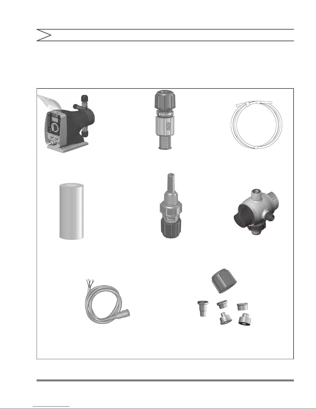
1.2 UNPACKING CHECK LIST
Your carton will contain many or all of the following
items. Please notify the carrier immediately if there
are any signs of damage to the pump or its parts.
SECTION 1 - INTRODUCTION
Metering Pump
Ceramic Foot
Valve Weight
Foot Valve Tubing (0 to 3 Rolls)
Injection Check
Valve
Four-Function Valve
(Optional)
External Control Cable
(0, 1, or 2 Cables)
Tube Connection
Hardware
Figure 1. Unpacking Check Sheet
2Instruction Manual

SECTION 2 - INSTALLATION
2.1 PUMP LOCATION AND INSTALLATION
Locate pump in an area convenient to solution tank
and electrical supply.
The pump should be accessible for routine
maintenance, and should not be operated in
ambient temperatures above 113°F (45°C).
If the pump will be exposed to direct sunlight, LMI®
black, UV resistant tubing should be installed.
This pump is cord connected and not intended
for permanent mounting to a building. However,
temporary mounting to stabilize the pump during
operation may be necessary as long as tools are
not required for the installation or removal of the
pump.
2.2 PUMP MOUNTING
The pump can be mounted in one of two ways:
A. FLOODED SUCTION (ideal installation); or
B. SUCTION LIFT - when suction lift is less
than 5 feet (1.5 m) for solutions having a
specic gravity of water or viscosity of less
than 100 cSt (centistokes). For denser or
more viscous solutions, consult distributor.
2.2.1 Flooded Suction
For ooded suction the pump is mounted at the
base of the storage tank. This installation is the
most trouble-free, and is recommended for very
low outputs, solutions that gasify, and high-viscosity
solutions. Since the suction tubing is lled with
solution, priming is accomplished quickly and the
chance of losing prime is reduced. A foot valve is
not necessary in a ooded suction installation.
When pumping downhill or into low or no pressure
system, a back pressure/anti-syphon device
should be installed to prevent overpumping or
syphoning. Although popular for all solutions, LMI®
recommends ooded suction installations for all
high-viscosity uid applications.
Note that suction conditions can affect
the performance of the pump. This effect
is more pronounced with lower pressure
pumps. Consult your distributor for additional
information.
Your LMI® metering pump must be mounted
so that the suction and discharge valves are
vertical. NEVER position pump head and
ttings horizontally.
3 Instruction Manual
Avoid this type of false ooded suction
Figure 2. Flooded Suction Pump Mounting
INCORRECT
CORRECT
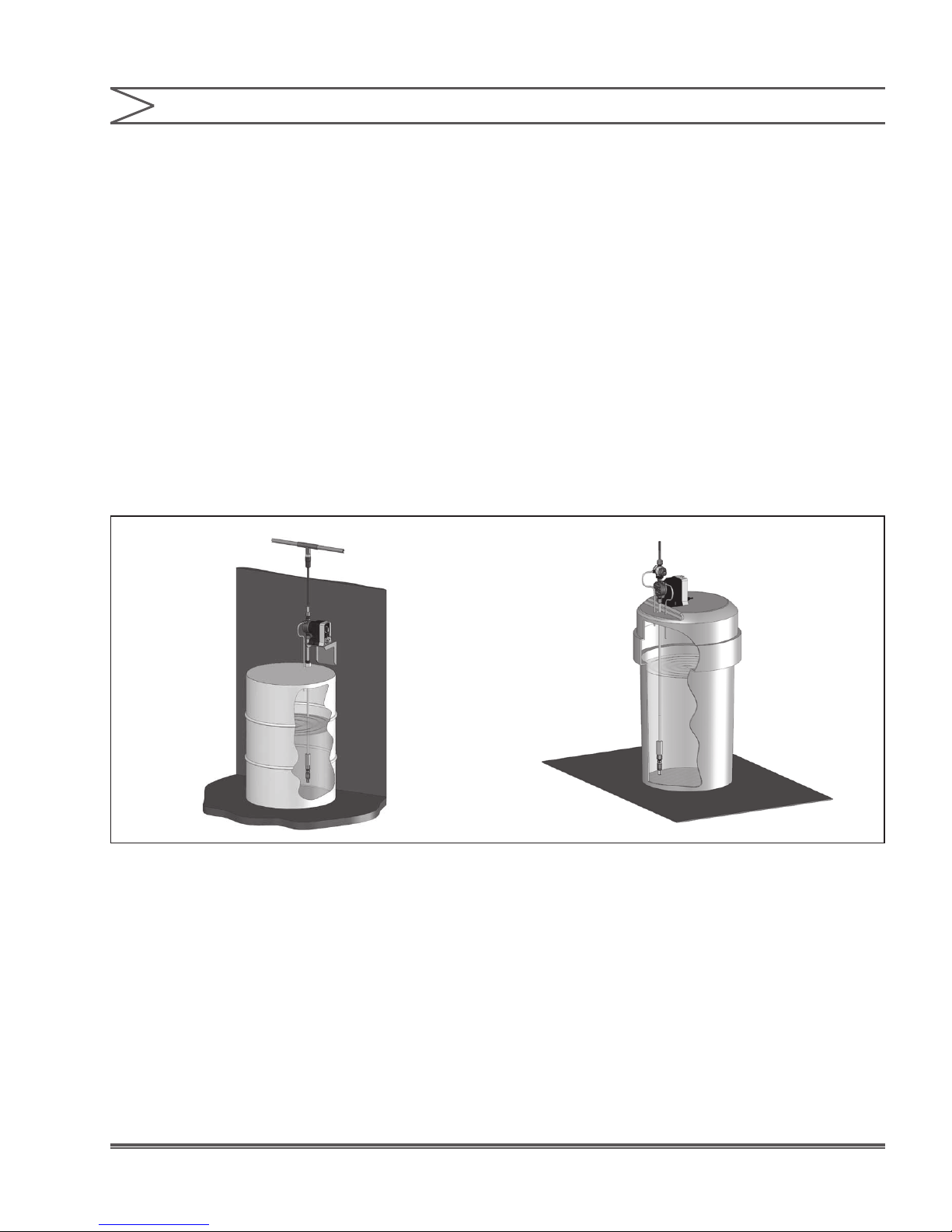
2.2.2 Suction Lift - Wall Bracket Mount
The pump may be mounted using an LMI® Wall
Mount Bracket Assembly (part no. 34643) directly
above the solution tank. A pump mounted in this
manner allows for easy changing of solution tanks
or drums.
2.2.3 Suction Lift - Tank Mount
The pump may be mounted on a LMI® 10-gallon
tank (part no. 27421), 35-gallon tank (part no.
27400), and 50-gallon tank (part no. 26350).
2.2.4 Suction Lift - Shelf Mount
The pump may be mounted on a shelf
(customer supplied) maintaining a suction lift of
less than 5 ft (1.5 m).
SECTION 2 - INSTALLATION
Figure 3
4Instruction Manual

SECTION 2 - INSTALLATION
2.3 TUBING CONNECTIONS
1. Insert tubing through Coupling Nut. Tubing
should enter the smaller end of the Coupling Nut
rst, orienting the larger opening of the Coupling
Nut toward the tubing end.
2a. For 1/4” OD tubing: Position the Female
Ferrule so that 1/4” to 3/8” (5-10 mm) of tubing
protrudes from the Female Ferrule. Orient the
raised collar of the Ferrule toward the Coupling
Nut (reference Figure 4).
2b. For 3/8” or 1/2” OD tubing: Position a Female
Ferrule about 1 inch (25 mm) from end of tubing.
Orient the raised collar of the Female Ferrule
toward the Coupling Nut. Then, insert the Male
Ferrule onto the end of the tube, pushing the
tube into the bottom of the groove in the Male
Ferrule. Then slide the Female Ferrule down
the tubing and with your ngers, press tightly
into the Male Ferrule (reference Figure 5).
3. Firmly hand tighten the Coupling Nut onto the
tting.
Note:
Tightening with pliers may cause the Ferrules
to break.
A. USE ONLY LMI® TUBING. ALWAYS USE LMI® SUPPLIED
TUBING WITH YOUR PUMP, AS THE TUBING IS SPECIFICALLY
DESIGNED FOR USE WITH THE PUMP FITTINGS.
B. DO NOT USE CLEAR VINYL TUBING ON THE DISCHARGE
SIDE OF THE PUMP. THE PRESSURE CREATED BY THE PUMP
CAN RUPTURE VINYL TUBING.
C. BEFORE INSTALLATION, ALL TUBING MUST BE CUT WITH
A CLEAN SQUARE END.
D. VALVE AND HEAD CONNECTIONS FROM THE FACTORY
ARE CAPPED OR PLUGGED TO RETAIN PRE-PRIME WATER.
REMOVE AND DISCARD THESE CAPS OR PLUGS BEFORE
CONNECTING TUBING.
DO NOT USE PLIERS OR PIPE WRENCH ON COUPLING NUTS
OR FITTINGS.
DO NOT REUSE FERRULES. USE ONLY NEW FERRULES.
Replacement Ferrules, and Coupling Nuts are
available as the following kit numbers.
Tube Size Kit Number
1/2” Tube 77382
3⁄8” Tube 77383
1/2” Tube 77384
3 x 6 mm Tube 77378
6 x 8 mm Tube 77379
9 x 12 mm Tube 77380
*One kit is needed for each end of the tube.
Coupling Nut
FerruleFemale
Tubing
3x6mm
1/4" O.D. or
O-Ring
Fitting
Figure 4
5 Instruction Manual
1/4" - 3/8"
(5-10 mm)
Tubing
6X8 mm
3/8”O.D. or
Figure 5
Coupling Nut
FerruleFemale
Tubing
9X12 mm
1/2”O.D. or
FerruleMale
O-Ring
Fitting

SECTION 2 - INSTALLATION
2.4 FOUR-FUNCTION VALVES (4-FV)
Your pump may be equipped with a 4-FV, or
standard discharge valve. If your pump is not
equipped with a four-function valve and you feel it
is needed in your application, it can be purchased
as an accessory. Contact your local LMI® stocking
distributor. The features of a 4-FV are listed below.
1. Pressure Relief: If the discharge line is over
pressurized, the valve opens sending solution
back to the supply tank.
2. Line Depressurization: Opening the relief knob
provides line drain back to the supply tank.
w
3. Anti-Syphon: Prevents syphoning when
pumping solution downhill or into a vacuum.
4. Back Pressure: Supplies approximately 20 psi
back pressure to prevent overpumping when
little or no system back pressure is present.
4-FV prevents syphoning when
pumping downhill into
low or no pressure
Figure 6. Typical Installations Requiring the Anti-Syphon
4-FV prevents syphoning when
pumping into a vacuum such as the
suction side of a recirculating pump
Feature of a Four-Function Valve
6Instruction Manual

SECTION 2 - INSTALLATION
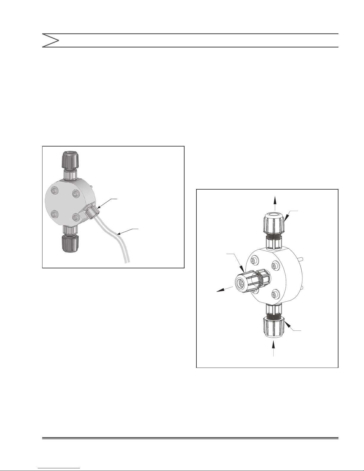
2.5 FOUR-FUNCTION VALVE
INSTALLATION
To install a 4-FV, the 4-FV Fitting and Coupling
Nut should be assembled with the appropriate
cartridges into the discharge port of the pump.
Use a 13/16” or 20 mm socket to tighten tting.
Tightening to 50 inch-pounds is recommended.
Do not over tighten.
To assemble the Four-Function Valve Body, insert
the large opening on the Four-Function Valve
Body into the 4-FV Coupling Nut and hand tighten.
You can position the valve to have the Bleed Nut
pressure relief port in any convenient location by
tightening the 4-FV Coupling Nut with the Bleed
Nut positioned 90º CCW from desired location,
then holding the 4-FV Coupling Nut stationary
while turning the 4-FV Body the nal 90º to desired
position. Next, insert the ¼” tubing through the
Bleed Nut. Ensure that about ¼” (6 mm) of tubing
is protruding through the tip of the Bleed Nut.
Firmly hand tighten the Bleed Nut in the hole on
the side of the 4-FV. This tubing should be routed
back to the supply tank. To ensure proper function
of the priming function, the end of this tubing should
not be submerged in the solution.
Figure 7. Four-Function Valve Tubing
Connection
THIS RETURN LINE TUBING
MUST BE SECURED TO ENSURE
PUMPED SOLUTION WILL SAFELY RETURN TO SUPPLY.
7 Instruction Manual
SECTION 2 - INSTALLATION
2.6 FASTPRIME™
The FASTPRIME™ Head is equipped with a valve
that allows for opening the head to atmospheric
pressure. When installing a pump equipped with
a FASTPRIME™ Head connect the 3/8” outer
diameter clear vinyl tubing provided with the pump
to the barbed nozzle. Route the vinyl return line
back to the solution tank. This tubing must not be
submerged in the solution.
FASTPRIMETMValve
3/8” Clear Vinyl Tubing
2.7 AUTOPRIME™
Pumps installed with the AUTOPRIME™ Liquid
End are equipped with a valve that allows
for constant removal of vapors and gasses
inherent with effervescent chemicals such as
Sodium Hypochlorite and Hydrogen Peroxide.
The valve keeps the pump primed automatically.
When installing a pump equipped with an
AUTOPRIME™ Liquid End, connect the 1/2” OD
Polyethylene tubing to the top vertical tting, and
route this line back to the supply tank. To ensure
priming, this tubing should not be submerged in the
solution. The horizontal tting is the discharge, and
the bottom vertical tting is the suction.
Return
to Supply
AUTOPRIME
Valve
TM
Figure 8. FASTPIME™ Head
Discharge
Valve
Discharge
Suction
Valve
Inlet
Figure 9. AUTOPRIME™ Liquid End Example
8Instruction Manual
SECTION 2 - INSTALLATION
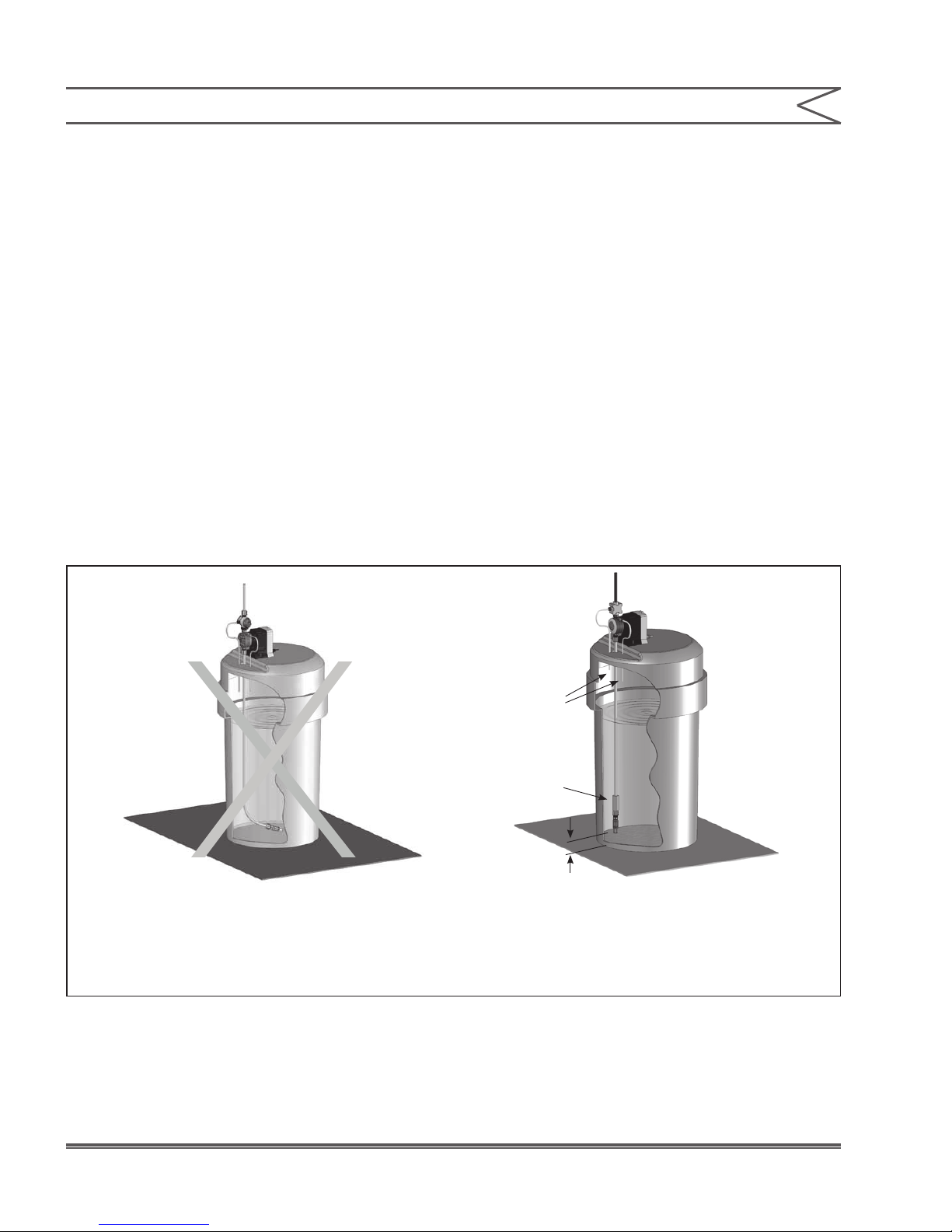
2.8 FOOT VALVE / SUCTION TUBING
INSTALLATION
The Foot Valve acts as a check valve to keep the
pump primed in suction lift applications.
The foot valve is designed to be submersed in
the solution tank or drum and must sit in a vertical
position at the bottom. Position approximately
2 inches (50 mm) off the bottom if the tank or drum
contains sediment.
Note:
Pump models equipped with high-viscosity liquid
ends are not equipped with foot valves. Flooded
suction is recommended. A 1/2” NPT connector
is included for ooded suction installations.
The ceramic weight, when installed, positions the
foot valve in a vertical position.
1. Attach the foot valve to one end of the
suction tubing (see Tubing Connections,
Section 2.3).
2. Slide the ceramic weight over the tubing
end until it contacts the top of the foot valve
coupling nut.
3. Place foot valve and tubing into the solution
tank. Check that the foot valve is vertical and
approximately 2 inches (50 mm) from the
bottom of the tank or drum (see illustration).
Connect the other end of the tubing to the
suction side of the pump head (bottom side)
(see Tubing Connections, Section 2.3).
Foot Valve
Tilted Sideways will not prime
INCORRECT
Figure 10. Foot Valve / Suction Tubing Installation
Return Lines
Must Not Be
Submerged
Use Ceramic
Weight
2.0 in. (50 mm)
for Sediment Accumulation
Foot Valve Must
Remain Vertical
CORRECT
9 Instruction Manual
SECTION 2 - INSTALLATION
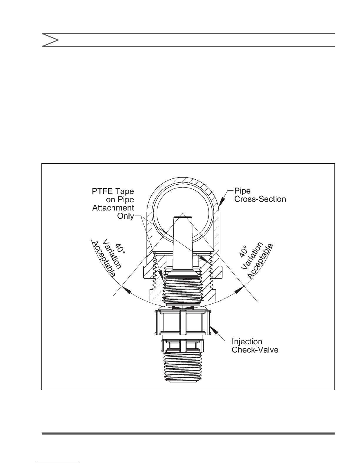
2.9 INJECTION CHECK VALVE AND
DISCHARGE TUBING INSTALLATION
The Injection Check Valve prevents backow from
a treated line. Install the injection check valve at
the location where chemical is being injected into
the system. Any size Female NPT tting or pipe
tee with a reducing bushing to ½” Female NPT will
accept the injection check valve. PTFE tape should
only be used on threads that are connected with
pipes.
When installing the Injection Check Valve, be sure
to position it so that the valve enters the bottom of
your pipe in a vertical position. Variations left and
right within 80° acceptable (See illustration).
After cutting an appropriate length of tubing,
connect tubing to the injection check valve
then back to the discharge side of the pump
head. Make sure it does not crimp or come into
contact with hot or sharp surfaces (see Tubing
Connections, Section 2.3).
Figure 11. Typical Injection Check Valve Installation
10Instruction Manual
SECTION 3 - OPERATION
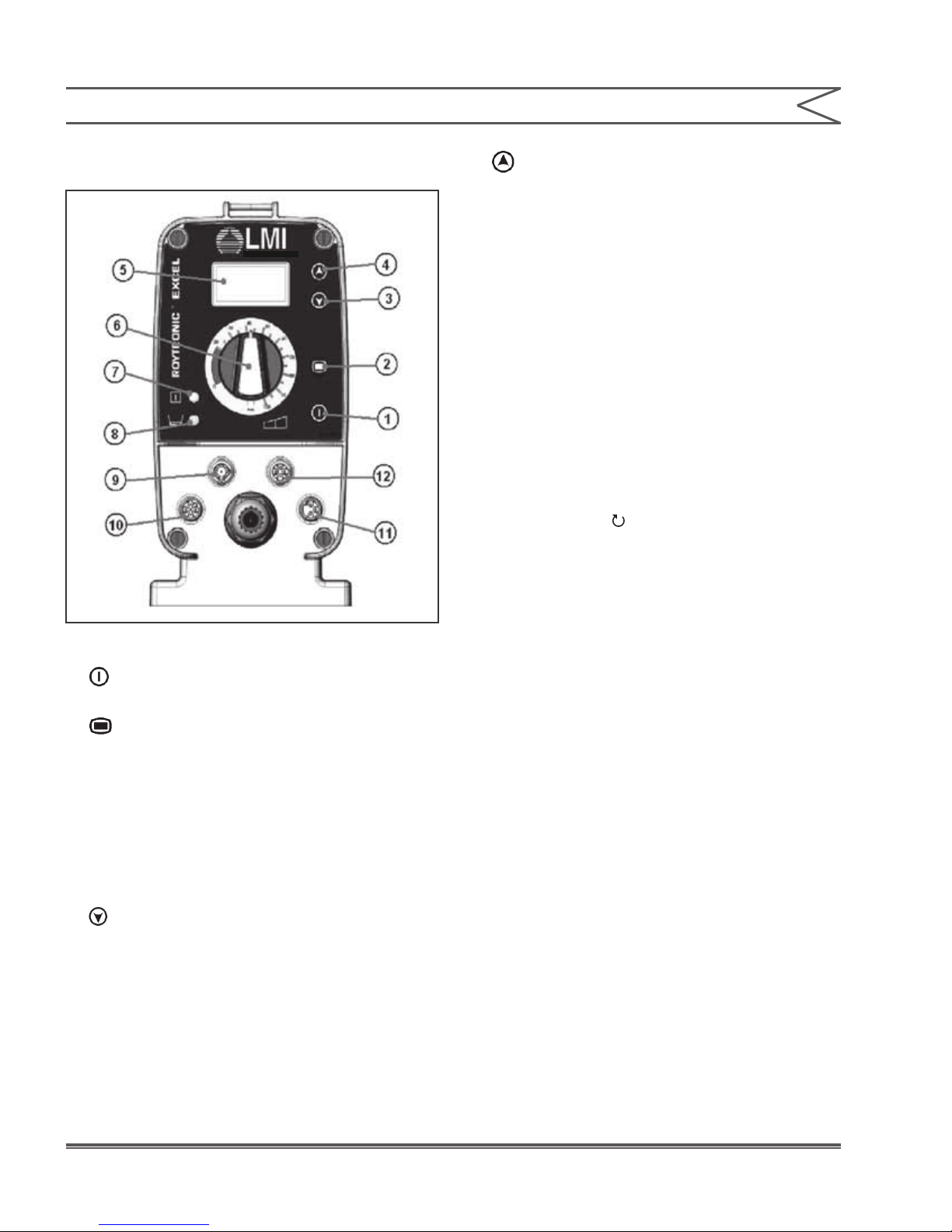
3.1 OUTPUT ADJUSTMENT
CONTROLS
4. Up Button: This button increases the stroke
speed of the pump. It will increase the stroke
speed by 1 each time it is pressed. If this button
is held down, it will rapidly increase the stroke
speed. When a speed of 59 strokes per hour
(SPH) is reached the speed can be further
increased by pressing this button again to enter
stroke per minute settings.
5. LCD Display: This display will show the stroke
speed of the pump. Pumps with theoretical
(AD2, AD8, AD9) or actual (AD9 when combined
with a ow meter) ow will display the ow
here.
6. Stroke Adjustment Knob: This knob provides
adjustment of the stroke length. Turning this
knob clockwise increases the stroke length,
which results in a higher amount of chemical
displaced per stroke. It is recommended that the
stroke range stay between 20% and 100%.
Figure 12
1. Power Button: This button allows convenient
starting and stopping of the pump.
2. Mode Selection Button: For pumps with
external control capability (AD8, AD9) this
button switches pump operation between
internal and external modes. When operating
in internal mode the Pulse Indicator Light will
ash green while pumping. When operating in
external mode the Pulse Indicator Light will ash
yellow while pumping.
3. Down Button: This button reduces the stroke
speed of the pump. It will reduce the stroke
speed by 1 each time it is pressed. If this button
is held down, it will rapidly reduce the stroke
speed. When a speed of 1 stroke per minute
(SPM) is reached the speed can be further
reduced by pressing this button again to enter
stroke per hour settings.
7. Pulse Indicator Light: This light will flash
green when pumping in internal mode and will
ash yellow when pumping in external mode.
The light is on between strokes and off during
the actual stroke.
8. Low-Level Indicator Light: For units with
Single-Level Float Sensors this light will turn
red when the Low-Level Sensor registers empty.
This will turn the pump off. For units compatible
with Dual-Level Sensors (AD8, AD9) the light
will turn yellow when a low level is registered,
and red when an empty level is registered.
The pump will turn off when it registers an empty
level.
11 Instruction Manual

SECTION 3 - OPERATION
9. Output, Alarm & Remote Mode Connector
(6-Pin): This connector is used for the special
functions associated with the AD9 controls.
For the AD9 this connector is associated with the
4-20ma out, Alarm Out, and Internal/ External
remote modes.
1. Alarm Out (Red/White) - Programmed as either
an Alarm Output or Internal/External mode
indicator. As an Alarm Output, pins 1 and 2
will give a closure (solid state) triggered by:
empty tank indication, input pulse error, exceed
batch error, or ow switch activation.For remote
mode indication it is open for internal mode and
closed for external.
2. Alarm Return (Red) - Return side for the above
pin 1 Alarm Out.
3. Remote Internal/External Mode (AD9)
(Green) - This pin is programmed as Internal/
External remote mode control for an AD9.
If programmed as the Internal/External control,
a closure will put the AD9 into external mode.
4. Pulse Out (AD9) (Red/Yellow) - On the AD9 this
pin gives a 100ms pulse output for each pump
stroke.
5. 4-20mA Out (AD9) (Red/Black) - On the AD9 this
pin is the positive 4-20ma output. This output
will show you 4ma when the pump is idle, 20ma
at max stroke speed.
6. Ground/Return Connection (Red / Blue) -
Common Ground
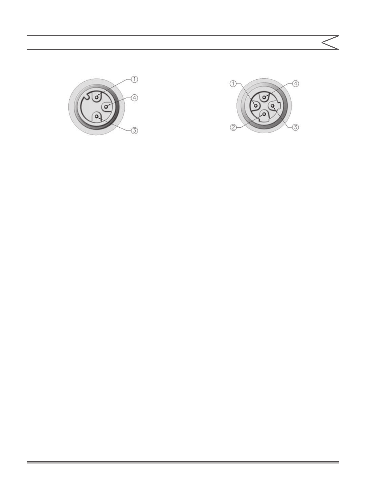
10. External Control Connector (5-Pin):
This connector is for the connection of various
options and accessories that can be used to
externally control the pump. The pin functions
(and the wire color for the standard LMI®
external control cable) are as follows:
1. Remote On/Off Signal (Brown)
2. Ground/Return Connection (White)
3. External Pulse Signal (Blue)
4. 24V 75 mA* Power Supply (Black)
5. 4-20mA Input Signal (Green/Yellow)
12Instruction Manual
SECTION 3 - OPERATION
11. Low-Level Connector (3-Pin):
This connector is for the connection of a Low-
Level Sensor (49246) or a Dual-Level Sensor
(49249). The Tank Empty input connections
are always active for all models in all functional
modes. The Tank Low input connections are
always active for models equipped with dual
level functionality (AD8, AD9). If the uid level
drops below the top float on a Dual-Level
Sensor, the Low-Level Indicator Light will turn
yellow. If the uid level drops below the oat on a
Low-Level Sensor, or the bottom oat on a Dual-
Level Sensor, the Low-Level Indicator Light will
turn red, and the pump will stop. The pump is
designed to recognize an open circuit as full and
a closed circuit as low or empty. There is a ve
second delay between triggering the sensor,
and the pump’s reaction. This is intended to
avoid triggering during relling your supply tank.
The pin functions are as follows:
1. Tank Empty Signal
12. Flow Monitor / Meter Connector (4-Pin):
This connector will be used with a Milton Roy
ow meter or the Milton Roy DIGI-PULSE™ ow
monitor (FM-ROY-9). The pin functions are as
follows:
1. Flow Meter In – A closure between this pin
and ground registers a pulse for the flow
meter/monitor.
2. 24 Volt 75 mA* Supply – Supply voltage for a
Milton Roy ow meter.
3. Ground/Return Connection – Common ground
4. Flow Meter Sense – The condition of this pin will
set the pump into the Digipulse or Flow Meter
mode. This will automatically occur when the
Milton Roy device is connected. A connection to
ground indicates the use of a ow meter, while
an open circuit indicates a ow monitor.
Note:
The total current output of the 5-pin and 4-pin
connectors should not exceed 75 mA.
3. Tank Low Signal
4. Ground/Return Connection
13 Instruction Manual

SECTION 3 - OPERATION
3.2 START-UP AND ADJUSTMENT
1. The pump is normally self-priming if suction lift
is 5 ft (1.5m) or less and the steps below are
followed.
2. Pumps are shipped from the factory with water
in the pump head to aid in priming.
3.2.1 Start-Up/Priming for FASTPRIME™
Heads (LE-XXXNX)
READ THIS ENTIRE SECTION
COMPLETELY BEFORE PRO-
CEEDING.
When all precautionary steps have been taken,
the pump is mounted, and the tubing is securely
attached, you may now start priming the pump.
1. Plug in or switch the pump on.
2. While the pump is running, set the Speed
Adjustment Knob and the Stroke Adjustment
Knob at 100%.
3. Turn The FASTPRIME™ knob 1 to 2 turns
counter-clockwise Q.
4. The suction tubing should begin to fill with
solution from the tank.
5. A small amount of solution will begin to discharge
out the return line of the FASTPRIME™ valve.
Once this happens, turn the knob clockwise P
until hand tight and SHUT THE PUMP OFF.
6. The pump is now primed.
7. Proceed to output adjustment, Section 3.3.
3.2.2 Start-Up/Priming for Pump Supplied
with 4-FV (LE-XXXSX or LE-XXXHX)
READ THIS ENTIRE SECTION
COMPLETELY BEFORE PRO-
CEEDING.
When all precautionary steps have been taken,
the pump is mounted, and the tubing is securely
attached, you may now start priming the pump.
1. Plug in or switch the pump on.
2. While the pump is running, set the Speed
Adjustment Knob and the Stroke Adjustment
Knob at 100%.
3. Open the relief side (black knob) of the 4-FV by
turning to the stop (about 1/8 turn).
4. The suction tubing should begin to fill with
solution from the tank.
5. A small amount of solution will begin to
discharge out the return line of the 4-FV. Once
this happens, return the knob to the 12:00
position and SHUT THE PUMP OFF.
6. The pump is now primed.
7. Proceed to output adjustment, Section 3.3.
Note:
If the pump does not self-prime, remove the
4-FV on the discharge side of the pump head.
Remove the check valve and pour water or
solution into the port until the head is lled.
Replace valve, then follow start up / priming
steps.
Note:
If the pump does not self-prime, remove the
tting on the discharge side of the pump head.
Remove the check valve and pour water or
solution into the port until the head is lled.
Replace valve, then follow start up/priming
steps.
14Instruction Manual

SECTION 3 - OPERATION
3.2.3 Start-Up/Priming for AUTOPRIME™
Heads (LE-XXXAX or LE-XXXHX)
READ THIS ENTIRE SECTION
COMPLETELY BEFORE PRO-
CEEDING.
When all precautionary steps have been taken,
the pump is mounted, and the tubing is securely
attached, you may prime the pump.
1. Plug in or switch on the pump.
2. While the pump is running, set the speed knob
and the stroke knob at 100%.
3. The suction tubing should begin to fill with
solution from the tank as the AUTOPRIME™
valve purges air from the pump head.
4. Once the solution begins to exit the pump
head through both the discharge valve and
the AUTOPRIME™ valve, SHUT THE PUMP
OFF.
5. The pump is now primed.
6. Proceed to output adjustment, Section 3.3.
3.3 OUTPUT ADJUSTMENT
Once the pump has been primed, an appropriate
output adjustment MUST be made. Pump output
should be calculated and adjustments made
accordingly.
3.3.1 Total Pump Output
Calculate the approximate output of the pump as
follows:
PUMP OUTPUT :
MAX PUMP OUTPUT X % SPEED X % STROKE
Example: AD251-938SI
Use Max Output (from dataplate on side of pump)
= 1 GPH (1 gallon per hour).
If the pump is set at 60 strokes per minute
(out of a possible 120 SPM) and 70% stroke length,
the approximate pump output is:
1.0 x 60/120 x 0.70 = 0.35 GPH.
Multiply by 24 (hours in one day) to calculate in
gallons per day.
Note:
When converting between different units,
remember these conversion factors:
1 Gallon = 3.785 Liters
1 Day = 1,440 Minutes
120 SPM = 7,200 SPH
IT IS IMPORTANT TO NOTE THAT
THIS IS ONLY AN APPROXIMATE
OUTPUT AND IT DOES NOT ACCOUNT FOR TOLERANCE
VARIATIONS IN PUMP COMPONENTS OR FLOW VARIATIONS
DUE TO PRESSURE SENSITIVITY, OR VISCOSITY EFFECTS.
VARIATIONS DUE TO THESE EFFECTS CAN BE SIGNIFICANT,
NECESSITATING CALIBRATION FOR YOUR PUMP.
15 Instruction Manual

SECTION 3 - OPERATION
3.3.2 Calibrating the Displayed Flow (AD2, AD8)
The Roytronic Excel Pumps are equipped
to display a theoretical flow rate based upon
the pump’s stroke speed and stroke length.
These calculations are based upon factory test
conditions which may be signicantly different
from your application. It is necessary for the user
to perform the following calibration procedure when
the pump is connected to your system, and using
the actual chemical. This one-point calibration
procedure will greatly improve the accuracy of
the pump’s calculated ow. The closer the pump’s
stroke length is to the typical use stroke length, the
more accurate the result. We recommend using the
approximate settings determined in section 3.3.1
as a starting point for calibration.
1. Prepare a ow measuring device such as a
graduated cylinder or a scale sensitive to
a gram.
2. Ensure the pump is primed following the
procedures in 3.2.
3. Put the pump into Internal Mode and use the
Power Button to turn the pump off.
4. Hold the Up Button and Down Button in
at the same time for 8 seconds until ‘CAL’ is
displayed on the LCD Display, then release
the buttons. Note ‘FLO’ will be displayed rst.
Continue to press the buttons until ‘CAL’ is
displayed.
5. Push the Power Button and release until
a “0” is displayed.
6. Note the reading on the calibration device.
If using a graduated cylinder note the starting
liquid level. If using a scale note the displayed
weight, or reset the scale’s display to zero.
Figure 13
D
column
D
tube
V
observed
Do not let
water level
drop below
top of weight
7. Push the Power Button and release to start
the pump. Notice that the display will count the
total number of strokes. (The screen will show
SPH).
8. Allow the pump to run; the accuracy will improve
with more strokes. Use the Power Button
to stop the pump. The number of strokes will
be displayed up to 999 strokes. If you will be
pacing the pump externally, note the number
of strokes.
9. Press and release the Power Button again.
This will display the pump’s estimated volume
pumped in mL. (The screen will show ml/h).
16Instruction Manual

SECTION 3 - OPERATION
10. Use the Up and Down Buttons to match
the displayed volume to the measured volume.
If using a graduated cylinder, the presence of
the tubing will cause the measurement to be
slightly higher than actual. The measurement
should be adjusted using the formulas shown
below. If using a scale, the number of grams
can be divided by the specific gravity of
your chemical to determine the number of
mL pumped. If the pump will be controlled
externally, the output volume per stroke can
be determined by dividing the measured output
by the number of strokes.
11. Once the displayed value has been adjusted,
hold and release the Power Button to return
the pump to internal mode.
V
where R = 1- ( D
Actual
= V
Tubes
Observed
/D
Column
* R
2
)
For accuracy, it is important that the water level
does not drop below the top of the ceramic foot
valve weight.
Note:
If you will be using the pump at a different
stroke length, or pressure, the pump should be
recalibrated under those conditions using the
procedure above to ensure accuracy.
3.4 METHODS OF EXTERNALLY
TRIGGERING OR PACING AD8 AND
AD9 PUMPS
Method of Triggering AD8 and AD9 Pumps
through External Control Connector.
Switch or transistors must be capable of switching
24V DC at 15 milliamperes. Minimum time in
low impedance state (ON) is 25 milliseconds.
Minimum time in high impedance state (OFF) is
50 milliseconds.
The remote on/off input (using pins 1 and 2) is
active in all modes. In the out-of-box conguration,
the pump will run when contacts are open.
The pump is monitoring these pins for a change in
closure condition. Regardless of the pump being
on or off, when the contacts close, then the pump
will turn on. When the contacts open, the pump
will turn off.
The Power Button overrides the remote on/off
and can still be used to turn the pump on and off.
If the contacts are closed when the on/off button
is pressed, the pump will turn off. To restart the
pump remotely, the contacts must be opened and
then closed again.
These pumps have two operating modes:
Local (Pulse Indicator Light ashes green) and
Remote (Pulse Indicator Light ashes yellow).
Pressing the Mode Selection Button switches
between Local and Remote modes. The default
conguration for operating mode is Local mode.
17 Instruction Manual
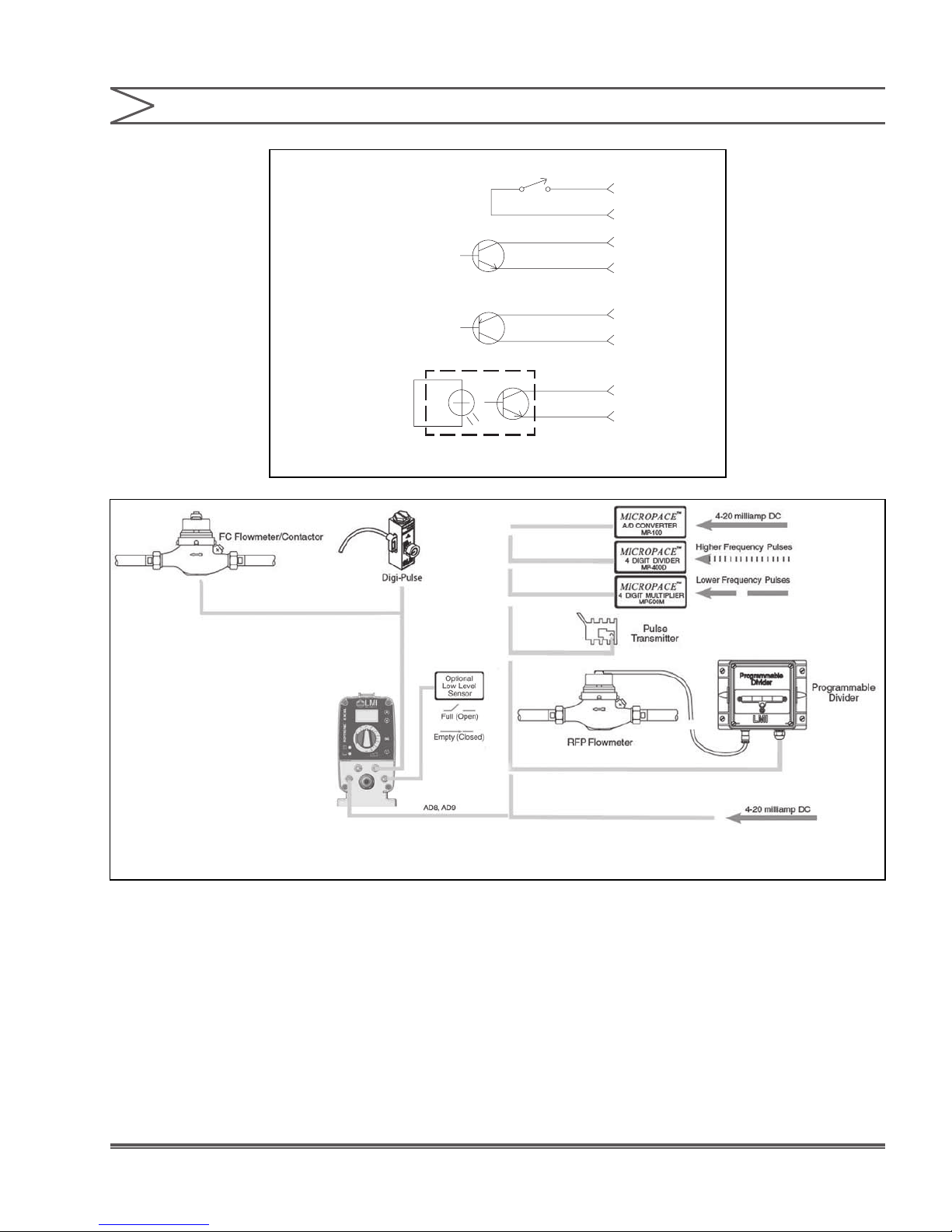
1. Switch Closure
Switch closing
triggers pump
2. NPN Transistor
Base goes high
to trigger pump
SECTION 3 - OPERATION
PIN
Blue
White
+ Blue
− White
3
2
3
2
3. PNP Transistor
Base goes low
to trigger pump
4. Opto
Isolator
+ Blue
− White
+ Blue
− White
3
2
3
2
Figure 14. Methods of Externally Triggering or Pacing AD8 and AD9 Pumps
18Instruction Manual

SECTION 3 - OPERATION
3.4.1 Control Modes
3.4.1.1 Local/Internal Mode
1. When in local mode Roytronic Excel pumps run
at the speed indicated on the LCD Display.
2. The stroking speed can be adjusted from the
maximum speed of 120 strokes per minute
(SPM) down to 1 stroke per hour (SPH).
3.4.1.2 Changing Displayed Flow Units
(AD2, AD8)
1. When in Internal Mode use the Power Button to
turn the pump off.
2. Hold the Up Button and Down Button in at the
same time until ‘FLO’ is displayed on the LCD
Display, then release the buttons.
3. Use the Up or Down Buttons to select the
desired units of measure.
4. Press the Power Button and the pump will
return to internal mode with the desired units
displayed.
3.4.1.3 Remote Mode (for AD8)
In Remote mode the pump can be controlled in
a variety of ways: pulse divide, pulse multiply,
or analog milliamp input. To cycle through the
available modes, start in external mode, then press
and hold the Power Button and Mode Selection
Button simultaneously for about ve seconds.
3.4.1.3.1 Divide Mode (for AD8)
The pump is in Divide Mode when a division
symbol (÷) is shown on the left-hand side of the
LCD Display. Use the Up Button and Down Button
to select the number of incoming pulses received
before a stroke occurs. Once the Power Button
is pushed to turn the pump on, the LCD Display
will show the approximate stroke rate of the pump
based on the incoming pulses.
If it is necessary to change the pulse duration
required to recognize a pulse from the factory
default of 60 ms, hold both the Up Button and
Down Button until a number appears followed by
the letter ‘m’. This number is the minimum required
time in milliseconds needed to count as a pulse.
Use the Up Button and Down Button to adjust this
number as needed. If no button is pressed for about
4 seconds, the pump will save the value and return
to the previous screen.
3.4.1.3.2 Multiply Mode (for AD8)
The pump is in Multiply Mode when a multiplication
symbol (X) is shown on the left-hand side of the
LCD Display. Use the Up Button and Down Button
to select the number of strokes that will occur for
each incoming pulse. Once the Power Button is
pushed to turn the pump on, the LCD Display
will count down the number of strokes starting
at the multiplier value each time a pulse input
is recognized. The strokes will occur every half
second until it has counted down to zero. The pump
will then wait for the next pulse input.
If it is necessary to change the pulse duration
required to recognize a pulse from the factory
default of 60 ms, hold both the Up Button and
Down Button until a number appears followed by
the letter ‘m’. This number is the minimum required
time in milliseconds needed to count as a pulse.
Use the Up Button and Down Button to adjust this
number as needed. If no button is pressed for about
4 seconds, the pump will save the value and return
to the previous screen.
19 Instruction Manual

3.4.1.3.3 Analog Mode (for AD8)
The pump is in Analog Mode when ‘mA’ is shown
on the left-hand side of the LCD Display.
Pressing the Up or Down Button will display ‘P1’
and the milliamp input that corresponds to zero
strokes. The Up and Down Buttons can be used
to adjust this value. Pressing the Power Button
(or waiting for about 8 seconds) will display ‘P2’
and the milliamp input that corresponds to max
stroke rate. Note that the maximum stroke rate
will be either 120 strokes per minute or 59 strokes
per hour. This depends on the stroke speed set in
Internal Mode.
SECTION 3 - OPERATION
20Instruction Manual

SECTION 4 - MAINTENANCE
4.0 SPARE PARTS REPLACEMENT AND
ROUTINE MAINTENANCE
LMI® metering pumps are designed for trouble-free
operation, yet routine maintenance of elastomeric
parts is essential for optimum performance.
This involves replacing the LIQUIFRAM™,
cartridge valves, O-rings, and the injection check
valve spring. LMI® recommends replacing these
parts at least once a year; however, frequency will
depend on your particular application.
4.1 DEPRESSURIZING THE DISCHARGE
LINE (FOR PUMPS EQUIPPED WITH
A 4-FV ONLY)
ALWAYS WEAR PROTECTIVE
CLOTHING, FACE SHIELD,
SAFETY GLASSES AND GLOVES WHEN PERFORMING ANY
MAINTENANCE OR REPLACEMENT ON YOUR PUMP.
TO REDUCE THE RISK OF
CHEMICAL SPLASH DURING
DISASSEMBLY OR MAINTENANCE, ALL INSTALLATIONS
SHOULD BE EQUIPPED WITH LINE DEPRESSURIZATION
CAPABILITY. USING LMI®’S FOUR-FUNCTION VALVE (4-FV) IS
ONE WAY TO INCLUDE THIS FEATURE.
4.2 DEPRESSURIZING THE
DISCHARGE LINE (FOR DOUBLE
BALL FASTPRIME™ HEADS ONLY)
ALWAYS WEAR PROTECTIVE
CLOTHING, FACE SHIELD,
SAFETY GLASSES AND GLOVES WHEN PERFORMING ANY
MAINTENANCE OR REPLACEMENT ON YOUR PUMP.
READ STEPS 1 AND 2 BELOW
BEFORE PROCEEDING.
1. Be sure the Injection Check Valve is properly
installed and is operating. If a shut off valve
has been installed downstream of the Injection
Valve, it should be closed.
BE SURE YOUR RELIEF TUBING
IS CONNECTED TO YOUR
FASTPRIME™ VALVE AND RUNS BACK TO YOUR SOLUTION
DRUM OR TANK.
2. Turn the FASTPRIME™ knob one-and-a-half
turns counter-clockwise. The discharge line
is now depressurized. Keep valve open until
solution drains back down the discharge tubing
into solution drum or tank. Then turn the knob
clockwise to tighten knob to closed position.
READ STEPS 1 AND 2 BELOW
BEFORE PROCEEDING.
1. Be sure the Injection Check Valve is properly
installed and is operating. If a shut off valve
has been installed downstream of the Injection
Valve, it should be closed.
BE SURE YOUR RELIEF TUBING
IS CONNECTED TO YOUR 4-FV
AND RUNS BACK TO YOUR SOLUTION DRUM OR TANK.
2. Turn the black knob on the 4-FV 1/8 turn
to the stop. Turn and hold the yellow knob
for a few seconds. The discharge line is
now depressurized. Keep both valve knobs
open until solution drains back down the
discharge tubing into the solution tank or drum.
Then release the yellow knob, and turn the black
knob to its normal position.
21 Instruction Manual

SECTION 4 - MAINTENANCE
4.3 LIQUIFRAM™ (DIAPHRAGM)
REPLACEMENT
ALWAYS WEAR PROTECTIVE
CLOTHING, FACE SHIELD, SAFETY
GLASSES AND GLOVES WHEN WORKING NEAR OR
PERFORMING ANY MAINTENANCE OR REPLACEMENT ON
YOUR PUMP. SEE SDS INFORMATION FROM SOLUTION
SUPPLIER FOR ADDITIONAL PRECAUTIONS.
LMI® metering pumps are designed for trouble-free
operation, yet routine maintenance of elastomeric
parts is essential for optimum performance. This
involves replacing the LIQUIFRAM™, cartridge
valves, O-rings and the injection check valve
spring. LMI® recommends replacing these parts at
least once a year; however, frequency will depend
on your particular application.
When replacing the LIQUIFRAM™, the cartridge
valves, or O-rings, the injection check valve spring
should also be replaced (see next Section 4.4). A
Spare Parts Kit or RPM PRO PAC™ kit containing
these parts may be obtained from your local
distributor.
2. Place the Foot Valve into a container of water or
other neutralizing solution. Turn the pump on to
ush the head assembly. Once the pump head
has been ushed, lift the Foot Valve out of the
solution and continue to pump air into the pump
head until the pump head is purged of water or
neutralizing solution.
Note:
If the liquid cannot be pumped due to
LIQUIFRAM™ rupture, carefully disconnect the
suction and discharge tubing using protective
clothing, gloves and face shield, immerse the
head in water or other neutralizing solution.
3. Remove the four metric screws and washers
from the head using an M4 Allen wrench.
4. Start the pump. While running, set the Stroke
Adjustment Knob to 0% and then turn the pump
off.
5. With the unit off, unscrew the LIQUIFRAM™
by carefully grasping the outer edge and
turning it counter-clockwise Q. Discard old
LIQUIFRAM™. Remove the Adapter Disk
(located behind the LIQUIFRAM™) and ensure
that the diameter of the raised section is the
same as the diameter of the replacement
LIQUIFRAM™.
Shaft
Seal
Drive
Liquid End
LIQUIFRAM
™
Adapter Disk
Figure 15. LIQUIFRAM™
(Diaphragm) Replacement
Replacing the LIQUIFRAM™:
1. Carefully depressurize, drain, and disconnect
the discharge line (see previous sections in this
manual).
6. Check condition of the Shaft Seal. Replace Shaft
Seal if necessary.
7. Replace the Adapter Disk so that the drain
hole of the disk is oriented downward, and the
mounting holes line up with the mounting holes
of the pump.
BE CAREFUL NOT TO SCRATCH
THE FLUOROFILM™ FACE OF THE
NEW LIQUIFRAM™.
8. Screw on the new LIQUIFRAM™ clockwise until
turned all the way in. Start the pump and turn
the stroke knob to 100%. Stop the pump.
9. Remount the pump head using the four (4)
screws and washers. Tighten in a criss-cross
pattern. Torque screws to 25 inch-pounds.
After one week of operation, recheck the screws
and tighten if necessary.
22Instruction Manual

SECTION 4 - MAINTENANCE
4.4 CARTRIDGE VALVE AND O-RING
REPLACEMENT
ALWAYS WEAR PROTECTIVE
CLOTHING, FACE SHIELD, SAFETY
GLASSES AND GLOVES WHEN WORKING ON OR PERFORMING
ANY MAINTENANCE OR REPLACEMENT ON YOUR PUMP. SEE
SDS INFORMATION FROM SOLUTION SUPPLIER FOR
ADDITIONAL PRECAUTIONS.
Refer to the LMI® Metering Pump Price List for
the proper Spare Parts Kit or RPM PRO PAC™
kit number or contact your local LMI® stocking
distributor.
1. Carefully depressurize and disconnect the
discharge line (see Section 4.1 or 4.2 in this
manual).
2. Place the Foot Valve into a container of water
or other neutralizing solution. Turn the pump on
to ush the head assembly. Once the pump has
been ushed, lift the Foot Valve out and continue
to pump to let air into the pump head until pump
is purged of water or neutralizing solution.
Note:
If the liquid cannot be pumped due to
LIQUIFRAM™ rupture, carefully disconnect the
suction and discharge tubing using protective
clothing, gloves and face shield. Remove the
four screws and washers from the head and
immerse the head in water or other neutralizing
solution.
Spare part replacement kits include specific
instructions for valve replacement. Please follow
the instructions included with the replacement kit.
3. Carefully disconnect one tubing connection and
tting at a time, then remove and replace the
worn valve and O-rings. If necessary, carefully
loosen stuck valves by prying side to side using
a small screwdriver through the center hole of
the valve.
Note:
Before disassembling the check valves, note
the orientation of the valve.
4. Install new check valves in each location.
Ensure that the cartridges are oriented
correctly.
23 Instruction Manual

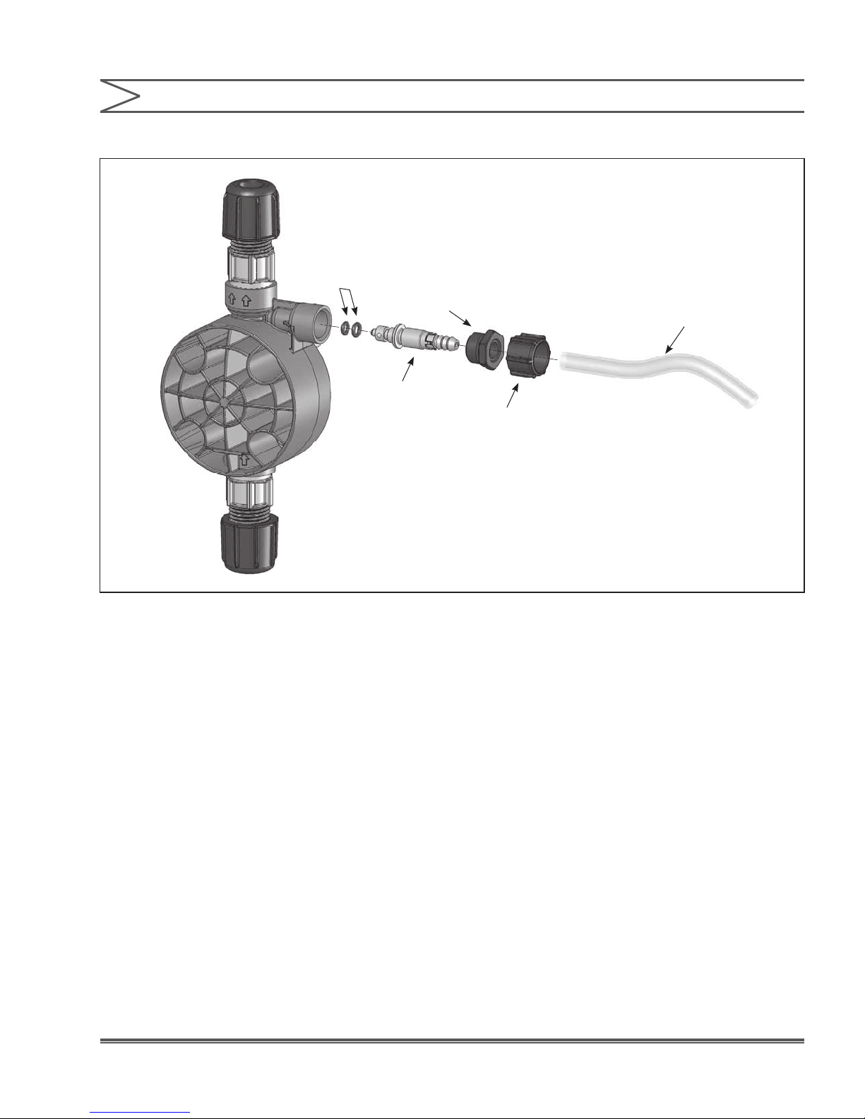
SECTION 4 - MAINTENANCE
4.5 INJECTION CHECK VALVE PARTS
REPLACEMENT
DEPRESSURIZE AND DRAIN
PIPELINE (OR ISOLATE INJECTION
CHECK VALVE POINT USING VALVES) SO THAT INJECTION
CHECK VALVE CAN SAFELY BE DISASSEMBLED.
ALWAYS WEAR PROTECTIVE
CLOTHING, FACE SHIELD, SAFETY
GLASSES AND GLOVES WHEN WORKING NEAR OR
PERFORMING ANY MAINTENANCE OR REPLACEMENT ON
YOUR PUMP. SEE SDS INFORMATION FROM SOLUTION
SUPPLIER FOR ADDITIONAL PRECAUTIONS.
Refer to the LMI® Metering Pump Price List for
the proper Spare Parts Kit or RPM PRO PAC™
kit number or contact your local LMI® stocking
distributor.
1. Isolate Injection Check Valve and depressurize
pipe or drain pipeline.
2. Carefully depressurize and disconnect the
discharge line (see Section 5.1 or 5.2 in this
manual).
Spare part replacement kits include specific
instructions for valve replacement. Please follow
the instructions included with the replacement kit.
3. Carefully disconnect the tubing leading to the
Injection Check Valve, then remove the Injection
Check Valve Fitting. Remove and replace the
worn spring, seat, ball, and O-ring.
Note:
Before disassembling the check valves, note
the orientation of the valve.
4. Install a new spring, seat, ball, and O-ring.
Ensure that the parts are oriented correctly.
Spring
Ball
Seat
O-Ring
Figure 16. Injection Check Valve Parts Replacement
O-Ring
Injection Check
Valve Fitting
24Instruction Manual
SECTION 4 - MAINTENANCE
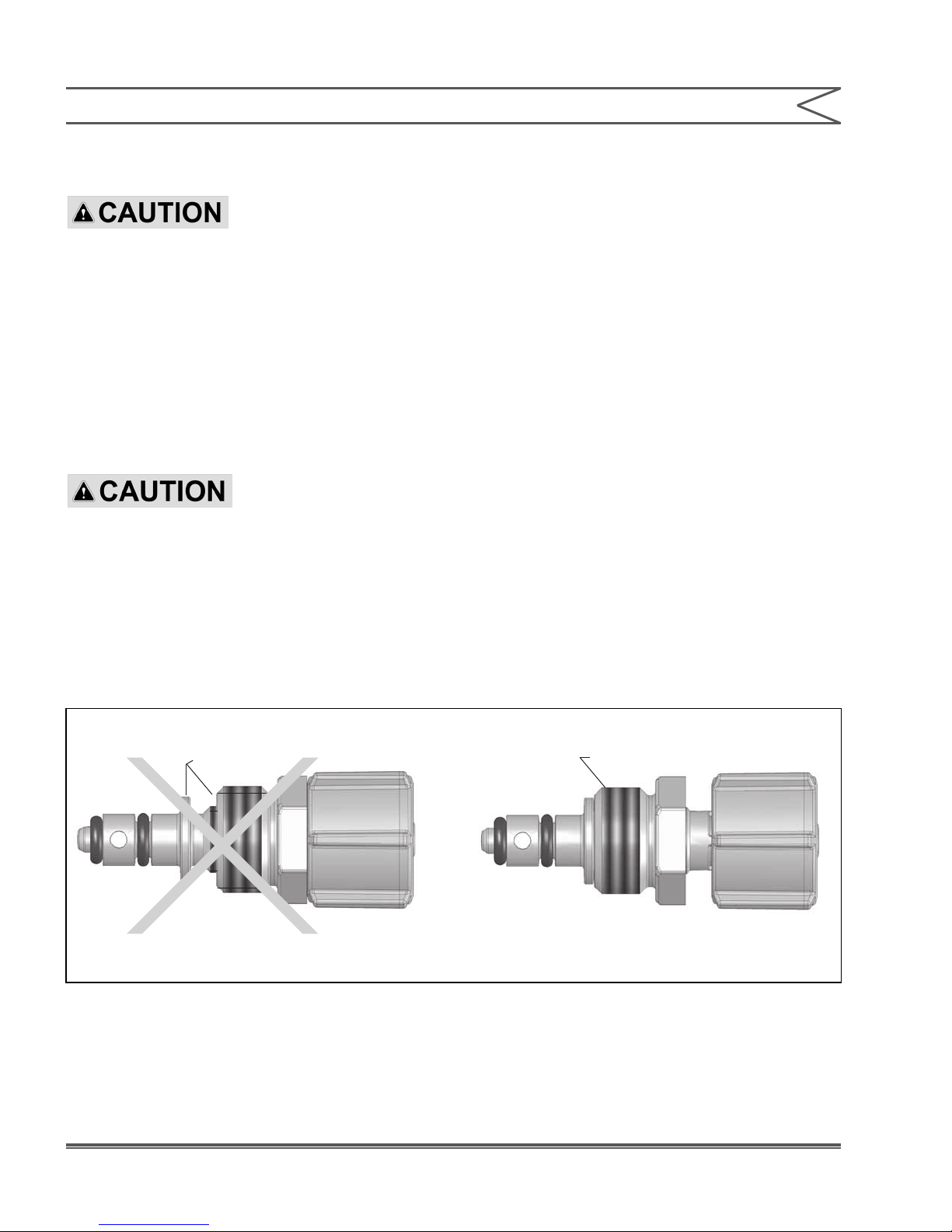
4.6 FASTPRIME™ VALVE O-RING
REPLACEMENT
ALWAYS WEAR PROTECTIVE
CLOTHING, FACE SHIELD, SAFETY
GLASSES AND GLOVES WHEN PERFORMING ANY
MAINTENANCE OR REPLACEMENT ON YOUR PUMP.
Refer to the LMI® Metering Pump Price List for
the proper Spare Parts Kit or RPM PRO PAC™
kit number or contact your local LMI® stocking
distributor.
1. Be sure the Injection Check Valve is properly
installed and is operating. If a shut off valve
has been installed downstream of the Injection
Valve, it should be closed.
BE SURE YOUR RELIEF TUBING
IS CONNECTED TO YOUR
FASTPRIME™ VALVE AND RUNS BACK TO YOUR SOLUTION
DRUM OR TANK.
2. Turn the FASTPRIME™ Knob one-and-a-half
turns counter-clockwise. This will depressurize
the head. Keep valve open. Carefully remove
the return line by gently pulling tubing and
moving it from side to side to gradually back
tubing off of the barbed tting.
3. Hold return line tubing upright until solution
drains back into solution drum or tank.
4. Using a 3/4” (or 19mm) socket or wrench
remove Retaining Nut, and pull out the entire
FASTPRIME™ Valve assembly. Remove and
replace the two small O-rings.
5. Reinsert the FASTPRIME™ Valve assembly
and retighten the Retaining Nut. Then turn
the FASTPRIME™ Knob clockwise to tighten
knob to closed position. To avoid damaging
the parts, it is important that the ange on the
FASTPRIME™ Valve is ush with the Retaining
Nut prior to reassembly.
6. Recut 1 to 2 inches off the tip of the return line
and ensure the end is squared. Press the return
line tubing on completely past the barbs.
Note gap between Flange
and Retaining Nut.
INCORRECT CORRECT
Figure 17a
25 Instruction Manual
No gap between Flange
and Retaining Nut.
O-Rings
O-Rings
FastPrimeTM Valve
FASTPRIME
TM
Valve
Retaining Nut
FASTPRIME
SECTION 4 - MAINTENANCE
3/8" Clear Vinyl Tubing
TM
Knob
Figure 17b. FASTPRIME™ Valve O-Ring Replacement
26Instruction Manual
SECTION 4 - MAINTENANCE
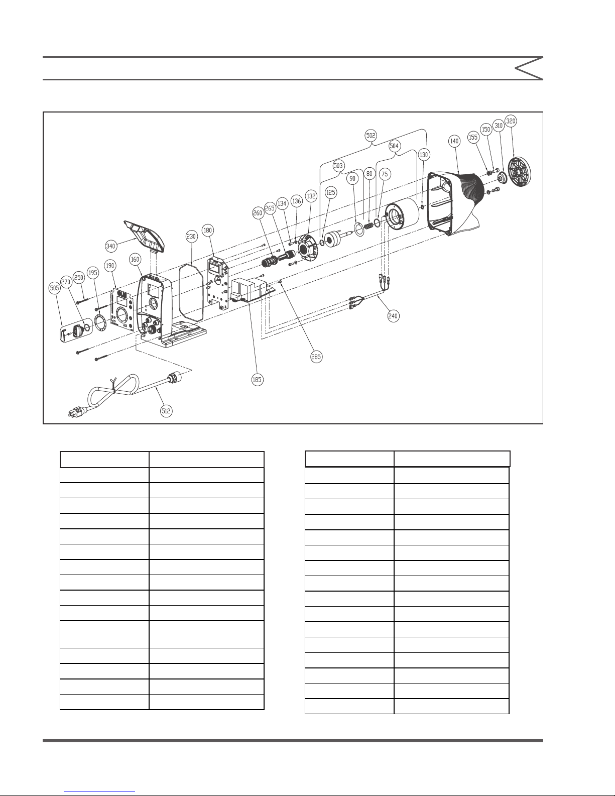
4.7 DRIVE PARTS LIST
Figure 18. Drive Parts List
Bubble Number Description
75 EPU O-Ring
80 EPU Return Spring
90 EPU Shim
125 Plunger O-Ring
130 Retaining Ring
132 Stroke Bracket
134 Stroke Bracket Screw
136 Stroke Bracket Washer
140 Drive Housing
150 EPU Attachment Bolt
155
160 Control Panel
180 Control Board
185 Power Board
190 Nameplate
EPU Attachment
Washer
Bubble Number Description
195 Stroke Dial
230 Control Panel O-Ring
240 Wire Harness
250 Drive Assembly Screws
260 Female Stroke Shaft
265 Male Stroke Shaft
270 Stroke Shaft O-Ring
285 PCB Attachment Screw
310 Shaft Seal
320 Adapter Disk
340 Clear Cover
502 EPU Assembly
503 Plunger Assembly
504 Pole Piece Assembly
505 Stroke Knob Assembly
512 Power Cord Assembly
Table 3. Drive Parts List
27 Instruction Manual
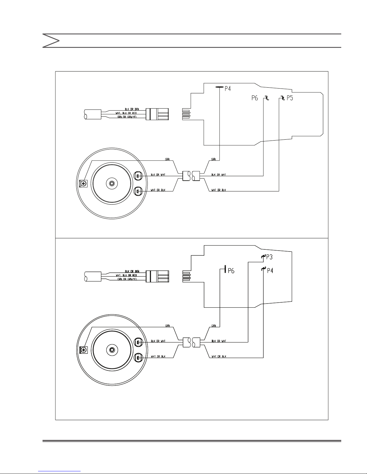
4.8 EPU WIRING DIAGRAM
AD8 / AD9 PULSER
POWER CORD
SECTION 4 - MAINTENANCE
EPU ASSEMBLY
AD2 PULSER
POWER CORD
EPU ASSEMBLY
Figure 19. EPU Wiring Diagram
28Instruction Manual

SECTION 4 - MAINTENANCE
4.9 LIQUID END PARTS
For the latest and most accurate information on
your liquid end, please refer to the Liquid End
Sheets available in the LMI® Online Library at:
www.lmipumps.com.
1. Select “Online Literature Library” in the
Navigation Bar on left.
THE FERRULE GEOMETRY WILL BE DIFFERENT.
2. Once on Online Literature Library use
“Product” drop down to select “Liquid Handling
Assemblies.”
3. Select “Gallery” or ”Index” to view Liquid End
sheets.
The following images are for reference and may
not represent your particular liquid end.
DEPENDING ON TUBING SIZE,
Figure 20. FASTPRIME™ Liquid End Assembly
29 Instruction Manual
DEPENDING ON CARTRIDGE DESIGN,
AN O-RING MAY BE PRESENT AS PART
OF THE ASSEMBLY

THE FERRULE GEOMETRY WILL BE DIFFERENT.
DEPENDING ON TUBING SIZE,
Figure 21. AUTOPRIME™ Liquid End Assembly
DEPENDING ON CARTRIDGE DESIGN,
AN O-RING MAY BE PRESENT AS PART
OF THE ASSEMBLY
30Instruction Manual

PIPE AND PIPE FITTINGS ARE
CUSTOMER SUPPLIED
DO NOT APPLY PTFE
TAPE TO THIS THREAD
OPTIONAL
PIPE AND PIPE FITTINGS ARE
CUSTOMER SUPPLIED
Figure 22. Stainless Steel Liquid End Assembly
31 Instruction Manual
OPTIONAL
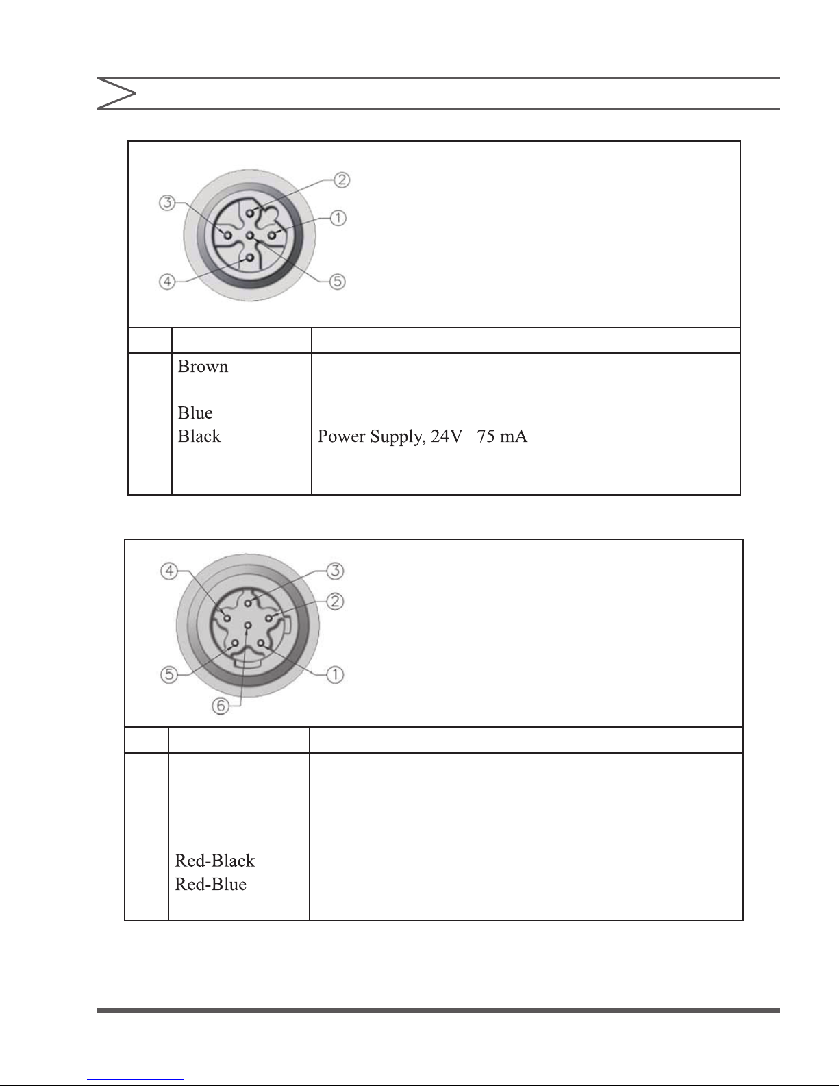
PIN WIRE SIGNAL
SECTION 5 - WIRING DIAGRAMS
5 PIN CONNECTOR
USE 5 PIN CABLE (LMI P/N 48414)
1
2
White
3
Remote On-Off
Ground-Return
External Pulse Input
4
5
Green-Yellow
4-20 mA Input
PIN WIRE SIGNAL
6 PIN CONNECTOR
USE 6 PIN CABLE (LMI P/N 49035)
1
2
3
4
Red-White
Red
Green
Red-Yellow
5
6
Alarm Output or Internal-External indicator
Alarm Return
Remote Internal-External mode
Pulse Output
4-20 mA Output
Ground-Return
32Instruction Manual
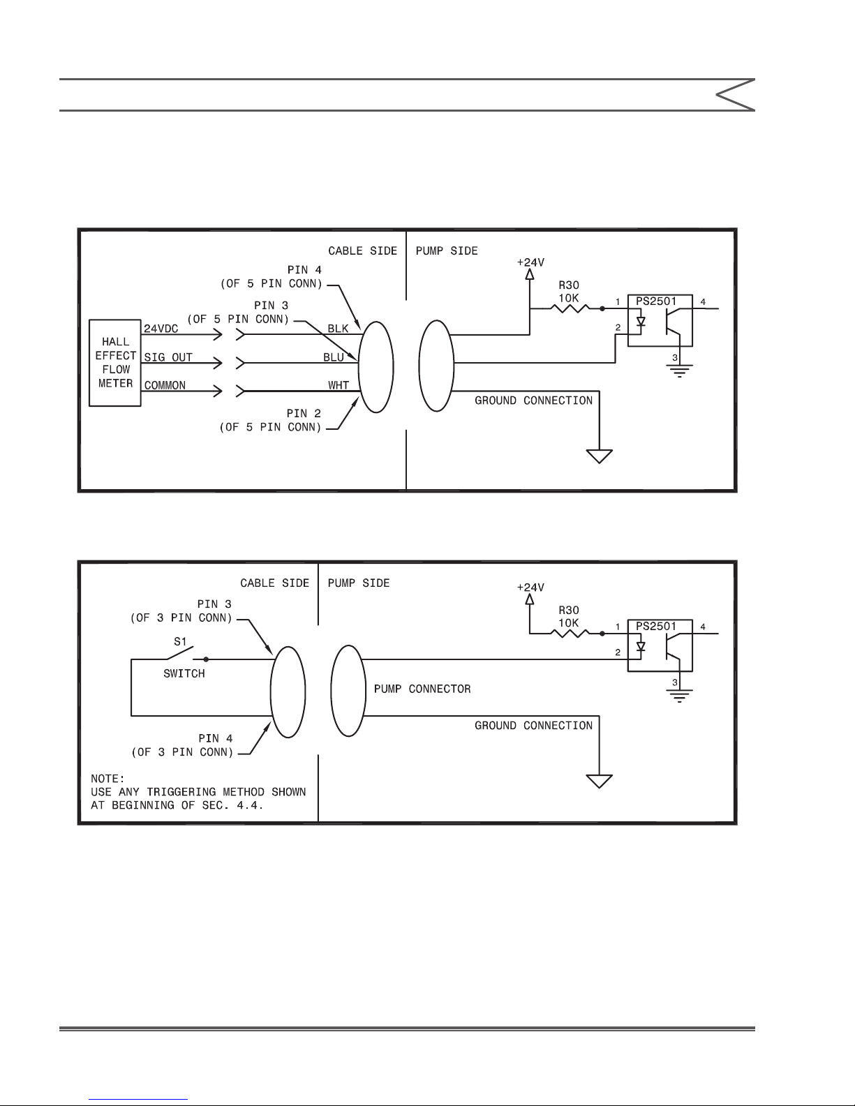
SECTION 5 - WIRING DIAGRAMS
INPUT WIRING DIAGRAM
HALL EFFECT FLOWMETER
INPUT CONNECTION REFERENCE:
TANK ON
INPUT CONNECTION REFERENCE:
NOTE:
A Cable Cord set for this application is included with an optional LMI® dual switch assembly P/N 49249.
33 Instruction Manual
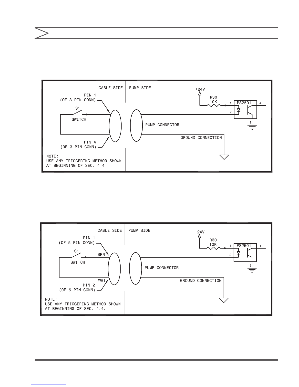
INPUT WIRING DIAGRAM
SECTION 5 - WIRING DIAGRAMS
TANK EMPTY
INPUT CONNECTION REFERENCE:
NOTE:
A Cable cord set for this application is included with an optional LMI® low level switch assembly
P/N 49246 or a LMI® dual level switch assembly P/N 49249.
REMOTE ON-OFF
INPUT CONNECTION REFERENCE:
34Instruction Manual

SECTION 5 - WIRING DIAGRAMS
INPUT WIRING DIAGRAM
EXTERNAL PULSE
INPUT CONNECTION REFERENCE:
INTERNAL / EXTERNAL CONTROL
INPUT CONNECTION REFERENCE:
35 Instruction Manual

INPUT WIRING DIAGRAM
SECTION 5 - WIRING DIAGRAMS
4 - 20 MA
INPUT CONNECTION REFERENCE:
NOTE:
0 to 20 input impedence is dynamic and will work with supply currents needing 130 Ohm or above
impedence.
36Instruction Manual

SECTION 5 - WIRING DIAGRAMS
OUTPUT WIRING DIAGRAM
OUTPUT CONNECTION REFERENCE:
PULSE
NOTE:
When using a “PULL UP” option use a 10K resistor and a 24VDC source (can be used with Pin 5 of
5 Pin CONN).
4 TO 20 MA
OUTPUT CONNECTION REFERENCE:
37 Instruction Manual

OUTPUT WIRING DIAGRAM
SECTION 5 - WIRING DIAGRAMS
ALARM
OUTPUT CONNECTION REFERENCE:
NOTE:
Use to switch on 24V source or less. Do not use to switch on AC line Voltage without Relay.
Relay coils should be 24VDC or less with maximum Current of 35 mA.
38Instruction Manual

SECTION 6 - TROUBLESHOOTING
PROBLEM POSSIBLE CAUSE SOLUTION
1. Pump not turned on or plugged in. 1. Turn on pump/plug in pump.
Pump Will Not
Prime
2. Output dials not set properly.
3. Foot Valve not in vertical position on
bottom of tank.
4. Pump suction lift too high.
5. Suction tubing is curved or coiled in
tank.
6. Fittings are over tightened.
7. Air trap in suction valve tubing.
8. Too much pressure at discharge
(Pumps without multi-function valve.)
2. Always prime pump with speed and stroke
at 100%.
3. Foot Valve must be vertical (see Foot Valve
Installation, Section 2.7).
4. Maximum suction lift is 5 ft (1.5 m). Pumps with
High Viscosity Liquid Handling Assemblies require
ooded suction.
5. Suction tubing must be vertical. Use LMI® ceramic
weight supplied with pump (see Section 2.7).
6. Do not overtighten ttings. This causes seal rings
to distort and not seat properly which causes
pump to leak back or lose prime.
7. Suction tubing should be as vertical as possible.
AVOID FALSE FLOODED SUCTION!
(see Section 2.2.1).
8. Shut off valves in pressurized line. Disconnect
tubing at injection check valve (see Priming
Section 3.2). When pump is primed, reconnect
discharge tubing.
Pump Loses
Prime
9. Air leak around tting.
1. Solution container ran dry.
2. Foot Valve is not in a vertical
position on the bottom of the tank.
3. Pump suction lift is too high.
4. Suction tubing is curved or coiled in
tank.
5. Fittings are over tightened.
6. Air trap in suction valve tubing.
7. Air leak on suction side. 7. Check for pinholes, cracks. Replace if necessary.
9. Check for missing or damaged O-rings at ends of
ttings.
1. Rell container with solution and reprime
(see Section 3.2).
2. Foot Valve must be vertical (see Foot Valve
Installation, Section 2.7).
3. Maximum suction lift is 5 ft (1.5 m). Pumps with
High Viscosity Liquid Handling Assemblies require
ooded suction.
4. Suction tubing must be vertical. Use LMI® ceramic
weight supplied with pump (see Section 2.7).
5. DO NOT OVERTIGHTEN FITTINGS. This causes
seal rings to distort and not seat properly which
causes pump to leak back or lose prime.
6. Suction tubing should be as vertical as possible.
AVOID FALSE FLOODED SUCTION!
(see Section 2.2.1).
39 Instruction Manual

PROBLEM POSSIBLE CAUSE SOLUTION
Leakage at
tubing
Low Output
or Failure to
Pump
Against
Pressure
1. Worn tubing ends.
1. Cut about 1 in (25 mm) off tubing and then
replace as before.
2. Replace tting if cracked. Carefully hand
2. Loose or cracked tting.
tighten ttings. DO NOT USE PIPE WRENCH.
An additional 1/8 or 1/4 turn may be necessary.
3. Worn seal rings. 3. Replace balls and seal rings(see Section 4.4).
4. Solution attacking Liquid
Handling Assembly.
1. Pump’s maximum pressure rating
is exceeded by injection pressure.
2. Worn Seal Rings.
4. Consult your local distributor for alternate
materials.
1. Injection pressure cannot exceed pump’s
maximum pressure. See pump data plate.
2. Worn seal rings or cartridge valves may need
replacement (see Section 4.4).
3. Ruptured LIQUIFRAM™. 3. Replace LIQUIFRAM™ (see Section 4.3).
4. Incorrect stroke length. 4. Recalibrate Output (see Section 3.3.2).
5. Tubing run on discharge may be
too long.
5. Longer tubing runs may create frictional losses
sufcient to reduce pump’s pressure rating
Consult factory for more information.
Failure to
Run
Excessive
Pump
Output
6. Remove Foot Valve strainer when pumping
6. Clogged Foot Valve strainer.
slurries or when solution particles cause strainer
to clog.
1. Pump not turned on or
plugged in.
1. Turn on or plug in pump.
2. Disassemble pump and measure resistance
2. EPU failure.
across the EPU terminals. If this measures as
an open circuit then the EPU should be
replaced. (see Section 4.8).
3. Pulser failure.
1. Syphoning. (Pumping downhill
without a multi-function valve).
2. Little or no pressure at injection
point.
3. The pulser should be replaced if EPU checks
out OK. Consult supplier or factory.
1. Move injection point to a pressurized location or
install an LMI® 4-FV (see Section 2.4).
2. If pressure at injection point is less than
25 psi (1.7 Bar), an LMI® 4-FV should be
installed see Section 2.4).
3. Excessive strokes per minute. 3. Replace pulser or resistor. Consult factory.
40Instruction Manual

We are a proud member of Accudyne Industries, a leading
global provider of precision-engineered, process-critical,
and technologically advanced ow control systems and
industrial compressors. Delivering consistently high levels
of performance, we enable customers in the most important
industries and harshest environments around the world
to accomplish their missions.
LMI® is a registered trademark of Milton Roy, LLC.
ROYTRONIC EXCEL™ is a trademark of Milton Roy, LLC.
LIQUIFRAM™ is a trademark of Milton Roy, LLC.
FASTPRIME™ is a trademark of Milton Roy, LLC.
AUTOPRIME™ is a trademark of Milton Roy, LLC.
DIGI-PULSE™ is a trademark of Milton Roy, LLC.
PRO PAC™ is a trademark of Milton Roy, LLC.
FLUOROFILM™ is a trademark of Milton Roy, LLC.
© 2015, 2011 Milton Roy, LLC.
info@lmipumps.com
www.lmipumps.com
 Loading...