

LMI Technologies Gocator 2330, Gocator 2320, Gocator 2342, Gocator 2150, Gocator 2170 User Manual
...
Gocator Line Profile Sensors
USER MANUAL
Gocator 2100, 2300, 2400 Series; Gocator 2880
Firmware version:4.7.x.xx
Document revision:D

Copyright
Copyright © 2017 by LMI Technologies, Inc. All rights reserved.
Proprietary
This document, submitted in confidence, contains proprietary information which shall not be
reproduced or transferred to other documents or disclosed to others or used for manufacturing or any
other purpose without prior written permission of LMI Technologies Inc.
No part of this publication may be copied, photocopied, reproduced, transmitted, transcribed, or
reduced to any electronic medium or machine readable form without prior written consent of LMI
Technologies, Inc.
Trademarks and Restrictions
Gocator™ is a registered trademark of LMI Technologies, Inc. Any other company or product names
mentioned herein may be trademarks of their respective owners.
Information contained within this manual is subject to change.
This product is designated for use solely as a component and as such it does not comply with the
standards relating to laser products specified in U.S. FDA CFR Title 21 Part 1040.
Contact Information
LMI Technologies, Inc.
9200 Glenlyon Parkway
Burnaby BCV5J 5J8
Canada
Telephone: +1 604-636-1011
Fax: +1 604-516-8368
www.lmi3D.com
Gocator Line Profile Sensors: User Manual
2

Table of Contents
Copyright 2
Table of Contents 3
Introduction 12
Gocator Overview 13
Safety and Maintenance 14
Laser Safety 14
Laser Classes 15
Precautions and Responsibilities 15
Class 3B Responsibilities 16
Nominal Ocular Hazard Distance (NOHD) 17
Systems Sold or Used in the USA 18
Electrical Safety 18
Handling, Clean ing, and Maintenance 19
Environment and Lighting 19
Getting Started 21
Hardware Overview 22
Gocator Sensor 22
Gocator Cordsets 22
Master 100 23
Master 400 / 800 / 1200 / 2400 24
Master 810 / 2410 25
Calibration Targets 27
System Overview 27
Standalone System 27
Dual-Sensor System 28
Multi-Sensor System 29
Installation 30
Mounting 30
Orientations 31
Grounding 33
Gocator 33
Recommended Practices for Cordsets 33
Master Network Controllers 34
Grounding When Using a DIN Rail (Master
810/2410) 35
Installing DIN Rail Clips: Master 810 or 2410 35
Configuring Master 810 36
Setting the Divider 37
Encoder Quadrature Frequency 37
Setting the Debounce Period 38
Rut-Scanning System Setup 38
Layout 38
System Setup 39
Software Configuration 40
System Operation 40
Network Setup 41
Client Setup 41
Gocator Setup 44
Running a Standalone Sensor System 44
Running a Dual-Sensor System 45
Next Steps 48
How Gocator Works 49
3D Acquisition 49
Clearance Distance, Field of Viewand
Measurement Range 50
Resolution and Accuracy 51
X Resolution 51
Z Resolution 52
Z Linearity 52
Profile Output 54
Coordinate Systems 54
Sensor Coordinates 54
System Coordinates 55
Part and Section Coordinates 58
Switching between Coordinate Systems 58
Spacing (Data Resampling) 59
Data Generation and Processing 60
Surface Generation 60
Part Detection 60
Sectioning 61
Part Matching 61
Measurement and Anchoring 62
Output and Digital Tracking 62
Gocator Web Interface 64
Unblocking Flash 64
Google Chrome 64
Internet Explorer 65
Firefox 66
Microsoft Edge 67
User Interface Overview 69
Toolbar 70
Creating, Saving and Loading Jobs (Settings) 71
Gocator Line Profile Sensors: User Manual
3

Recording, Playback, and Measurement
Simulation 72
Recording Filtering 74
Downloading, Uploading, and Exporting
Replay Data 75
Metrics Area 78
Data Viewer 78
Status Bar 78
Log 79
Frame Information 79
Interface Language 80
Quick Edit Mode 80
Management and Maintenance 81
Manage Page Overview 81
Sensor System 82
Dual- and Multi-sensor Systems 82
Buddy Assignment 83
Over Temperature Protection 84
Sensor Autostart 84
Layout 84
Device Exp osure Multiplexing 91
Networking 92
Motion and Alignment 93
Alignment Reference 93
Encoder Resolution 94
Encoder Value and Frequency 94
Travel Speed 94
Jobs 95
Security 96
Maintenance 97
Sensor Backups and Factory Reset 98
Firmware Upgrade 99
Support 100
Support Files 101
Manual Access 101
Software Development Kit 102
Scan Setup and Alignment 103
Scan Page Overview 103
Scan Modes 104
Triggers 105
Trigger Examples 109
Trigger Settings 110
Maximum Input Trigger Rate 112
Maximum Encoder Rate 112
Sensor 112
Active Area 112
Tracking Window 114
Transformations 115
Exposure 117
Single Exposure 118
Dynamic Exposure 118
Multiple Exposure 119
Spacing 121
Sub-Sampling 121
Spacing In terval 122
Advanced 123
Material 124
Camera Gain and Dynamic Exposure 125
Alignment 125
Alignment States 125
Alignment Types 126
Alignment: with and without Encoder
Calibration 126
Aligning Sensors 126
Clearing Alignment 130
Filters 130
Gap Fillin g 131
Median 132
Smoothing 132
Decimation 133
Surface Generation 134
Part Detection 137
Part Detection Status 141
Edge Filtering 143
Data Viewer 144
Data Viewer Controls 144
Video Mode 147
Exposure Information 147
Exposures 147
Overexposure and Underexposure 148
Spots and Dropouts 149
Profile Mode 150
Surface Mode 152
Height Map Color Scale 155
Sections 155
Gocator Line Profile Sensors: User Manual
4

Region Definition 157
Intensity Output 158
Models 159
Model Page Overview 159
Part Matching 160
Using Edge Detection 161
Creating a Model 164
Modifying a Model's Edge Points 166
Adjusting Target Sensitivity 169
Setting the Match Acceptance Criteria 170
Running Part Matching 170
Using Bounding Box and Ellipse 170
Configuring a Bounding Box or an Ellip se172
Running Part Matching 173
Using Part Matching to Accept or Reject a
Part 174
Sections 174
Creating a Section 177
Deleting a Section 179
Measurement 180
Measure Page Overview 180
Data Viewer 181
Tools Panel 182
Adding and Configuring a Measurement
Tool 182
Source 183
Streams (Sections) 184
Regions 184
Feature Points 187
Fit Lines 189
Geometric Features 190
Decisions 191
Filters 192
Measurement Anchoring 194
Enabling and Disabling Measurements 199
Editing a Tool or Measurement Name 200
Changing a Measurement ID 200
Duplicating a Tool 201
Removing a Tool 201
Reordering Tools 202
Profile Measurement 202
Area 202
Measurements, F eatures, and Settings 204
Bounding Box 206
Measurements, F eatures, and Settings 207
Bridge Value 209
Understanding the Window and Skip
Settings 210
Measurements and Settings 211
Using Window and StdDev as Metrics
Measurements 213
Circle 214
Measurements, F eatures, and Settings 215
Dimension 216
Groove 219
Intersect 223
Measurements, F eatures, and Settings 223
Line 225
Measurements, F eatures, and Settings 226
Panel 229
Position 232
Measurements, F eatures, and Settings 233
Round Corner 235
Strip 238
Script 242
Surface Measurement 244
Bounding Box 245
Measurements, F eatures, and Settings 246
Countersunk Hole 249
Measurements, F eatures, and Settings 252
Dimension 258
Edge 262
Paths and Path Profiles 265
Measurements, F eatures, and Settings 266
Ellipse 276
Measurements, F eatures, and Settings 277
Hole 279
Measurements, F eatures, and Settings 281
Measurement Region 283
Opening 284
Measurements, F eatures, and Settings 287
Measurement Region 291
Plane 291
Measurements, F eatures, and Settingss 294
Position 295
Measurements, F eatures, and Settingss 296
Gocator Line Profile Sensors: User Manual
5

Stud 298
Measurements, F eatures, and Settings 300
Measurement Region 302
Volume 302
Script 304
Feature Measurement 305
Dimension 305
Intersect 309
Scripts 313
Built-in Functions 313
Output 318
Output Page Overview 318
Ethernet Output 319
Digital Output 323
Analog Output 326
Serial Output 327
Dashboard 330
Dashboard Page Overview 330
State and Health Information 330
Statistics 332
Measurements 332
Performance 332
Gocator Emulator 334
System Requirements 334
Limitations 335
Downloading a Support File 335
Running the Emulator 336
Adding a Scenario to the Emulator 337
Running a Scenario 337
Removing a Scenario from the Emulator 338
Using Replay Protection 339
Stopping and Restarting the Emulator 339
Running the Emulator in Default Browser 339
Working with Jobs and Data 340
Creating, Saving, and Loading Jobs 340
Playback and Measurement Simulation 341
Downloading, Uploading, and Exporting
Replay Data 342
Downloading and Uploading Jobs 345
Scan, Model, and Measurement Settings 346
Calculating Potential Maximum Frame Rate 346
Protocol Output 347
Remote Operation 347
Gocator Accelerator 349
System Requirements 350
Benefits 350
Installation 350
Gocator Accelerator Utility 350
Dashboard and Health Indicators 353
SDK Application Integration 353
Gocator Device Files 355
Live Files 355
Log File 355
Job File Structure 356
Job File Components 356
Accessing Files and Components 357
Configuration 357
Setup 358
Filters 359
XSmoothing 359
YSmoothing 359
XGapFilling 360
YGapFilling 360
XMedian 360
YMedian 360
XDecimation 361
YDecimation 361
XSlope 361
YSlope 361
Trigger 362
Layout 363
Alignment 364
Disk 365
Bar 365
Plate 366
Devices / Device 366
Tracking 369
Material 369
IndependentExposures 371
SurfaceGeneration 371
FixedLength 372
VariableLength 372
Rotational 372
SurfaceSections 373
Gocator Line Profile Sensors: User Manual
6

ProfileGeneration 373
FixedLength 374
VariableLength 374
Rotational 374
PartDetection 374
EdgeFiltering 376
PartMatching 376
Edge 376
BoundingBox 376
Ellipse 377
Replay 378
RecordingFiltering 378
Conditions/AnyMeasurement 378
Conditions/AnyData 379
Conditions/Measurement 379
Streams/Stream (Read-only) 379
ToolOptions 380
MeasurementOptions 381
FeatureOptions 381
StreamOptions 382
Tools 382
Profile Types 382
ProfileFeature 382
ProfileLine 383
ProfileRegion2d 383
SurfaceTypes 383
Region3D 383
SurfaceFeature 383
SurfaceRegion2d 384
Geometric Feature Types 384
Parameter Types 384
ProfileArea 386
ProfileBoundingBox 388
ProfileBridgeValue 389
ProfileCircle 391
ProfileDimension 392
ProfileGroove 394
ProfileIntersect 396
ProfileLine 397
ProfilePanel 399
ProfilePosition 402
ProfileRoundCorner 403
ProfileStrip 405
Script 407
SurfaceBoundingBox 407
SurfaceCsHole 409
SurfaceDimension 412
Tool 414
SurfaceEllipse 417
SurfaceHole 418
SurfaceOpening 421
SurfacePlane 423
SurfacePosition 425
SurfaceStud 426
SurfaceVolume 429
Tool 431
Tool 432
Custom 433
Output 434
Ethernet 434
Ascii 437
EIP 437
Modbus 437
Digital0 and Digital1 438
Analog 438
Serial 439
Selcom 440
Ascii 440
Transform 440
Device 441
Part Models 442
Edge Points 443
Configuration 443
Protocols 445
Gocator Protocol 445
Data Types 446
Commands 446
Discovery Commands 447
Get Address 447
Set Address 448
Get Info 449
Control Commands 450
Protocol Version 451
Get Address 451
Gocator Line Profile Sensors: User Manual
7

Set Address 452
Get System Info V2 452
Get System Info 455
Get States 456
Log In/Out 457
Change Password 457
Assign Bud dies 458
Remove Buddies 459
Set Buddy 459
List Files 459
Copy File 460
Read File 460
Write File 461
Delete File 462
User Storage Used 462
User Storage Free 462
Get Default Job 463
Set Default Job 463
Get Loaded Job 463
Get Alignment Reference 464
Set Alignment Reference 464
Clear Alignment 465
Get Timestamp 465
Get Encoder 465
Reset En coder 466
Start 466
Scheduled Start 467
Stop 467
Get Auto Start Enabled 467
Set Auto Start Enabled 468
Get Voltage Settings 468
Set Voltage Settings 469
Get Quick Edit Enab led 469
Set Quick Edit Enabled 469
Start Alignment 470
Start Exposure Auto-set 470
Software Trigger 471
Schedule Digital Output 471
Schedule Analog Output 472
Ping 472
Reset 473
Backup 473
Restore 474
Restore Factory 474
Get Recording Enabled 475
Set Recording Enabled 475
Clear Replay Data 476
Get Playback Source 476
Set Playback Source 476
Simulate 477
Seek Playback 477
Step Playback 478
Playback Position 478
Clear Measurement Stats 479
Read Live Log 479
Clear Log 479
Simulate Unaligned 480
Acquire 480
Acquire Unaligned 480
Create Model 481
Detect Edges 481
Add Tool 482
Add Measurement 482
Read File (Progressive) 483
Export CSV (Progressive) 483
Export Bitmap (Progressive) 484
Get Runtime Variable Count 485
Set Runtime Variables 485
GetRuntimeVariables 486
Upgrade Commands 486
Start Upgrade 487
Start Upgrade Extended 487
Get Upgrade Status 487
Get Upgrade Log 488
Results 488
Data Results 488
Stamp 489
Video 490
Profile 490
Resampled Profile 491
Profile Inten sity 492
Resampled Profile Intensity 492
Surface 493
Surface Intensity 494
Gocator Line Profile Sensors: User Manual
8

Surface Section 494
Surface Section Intensity 495
Measurement 496
Operation Result 496
Exposure Calibration Result 497
Edge Match Result 497
Bounding Box Match Result 498
Ellipse Match Result 498
Event 498
Feature Point 499
Feature Line 499
Health Results 499
Modbus Protocol 505
Concepts 505
Messages 505
Registers 506
Control Registers 507
Output Registers 508
State 508
Stamp 509
Measurement Registers 510
EtherNet/IP Protocol 512
Concepts 512
Basic Object 513
Identity Object (Class 0x01) 513
TCP/IP Object (Class 0xF5) 513
Ethernet Link Object (Class 0xF6) 513
Assembly Object (Class 0x04) 514
Command Assembly 514
Runtime Variable Configuration Assembly 515
Sensor State Assembly 516
Sample State Assembly 517
Implicit Messaging Command Assembly 518
Implicit Messaging Output Assembly 519
ASCIIProtocol 521
Connection Settings 521
Ethernet Communication 521
Serial Communication 522
Polling Operation Commands (Ethernet Only) 522
Command and Reply Format 523
Special Characters 523
Command Channel 523
Start 524
Stop 524
Trigger 524
LoadJob 525
Stamp 525
Clear Alignment 526
Moving Align ment 526
Stationary Alignment 526
Set Runtime Variables 527
Get Runtime Variables 527
Data Channel 527
Result 527
Value 528
Decision 529
Health Channel 529
Health 530
Standard Result Format 530
Custom Result Format 531
Selcom Protocol 532
Serial Communication 532
Connection Settings 532
Message Format 532
Development Kits 534
GoSDK 534
Setup and Locations 535
Class Reference 535
Examples 535
Sample Project Environment Variable 535
Header Files 535
Class Hierarchy 535
GoSystem 536
GoSensor 536
GoSetup 536
GoLayout 536
GoTools 537
GoTransform 537
GoOutput 537
Data Types 537
Value Types 537
Output Types 537
GoDataSet Type 538
MeasurementValues and Decisions 539
Gocator Line Profile Sensors: User Manual
9

Operation Workflow 539
Initialize GoSdk APIObject 540
Discover Sensors 541
Connect Sensors 541
Configure Sensors 541
Enable Data Channels 541
Perform Operations 541
Limiting Flash Memory Write Operations 543
GDK 544
Benefits 544
Supported Sensors 544
Typical Workflow 545
Installation and Class Reference 545
Required Tools 545
Getting Started with the Example Code 546
Building the Sample Code 546
Tool Registration 546
Tool Definitions 547
Entry Functions 547
Parameter Configurations 548
Graphics Visualization 549
Debuggin g Your Measurement Tools 551
Debuggin g Entry Functions 552
Tips 552
Backward Compatibility with Older Versions
of Tools 552
Define new parameters as optional 552
Configuration Versioning 552
Version 554
Common Programming Operations 554
Input Data Objects 554
Setup and Region Info during Tool
Initialization 555
Computing Region Based on the Offset
from an Anchor Source 555
Part Matching 556
Accessing Sensor Local Storage 556
Print Output 556
Tools and Native Drivers 557
Sensor Discovery Tool 557
GenTL Driver 558
16-bit RGB Image 562
16-bit Grey Scale Image 563
Registers 565
XMLSettings File 566
Interfacing with Halcon 566
Setting Up Halcon 567
Halcon Procedures 570
Generating Halcon Acquisition Code 574
CSV Converter Tool 575
MountainsMap Transfer Tool 577
Configuring Gocator to Work with the Transfer
Tool 578
Using the Mountains Map Transfer Tool 578
Troubleshooting 581
Specifications 583
Sensors 583
Gocator 2100 & 2300 Series 583
Gocator 2320 586
Gocator 2130 and 2330 588
Gocator 2140 and 2340 590
Gocator 2342 592
Gocator 2150 and 2350 594
Gocator 2170 and 2370 597
Gocator 2375 600
Gocator 2180 and 2380 603
Gocator 2400 Series 606
Gocator 2410 608
Gocator 2420 611
Gocator 2880 Sensor 614
Gocator 2880 615
Sensor Connectors 618
Gocator Power/LAN Connector 618
Grounding Shield 618
Power 619
Laser Safety Input 619
Gocator I/O Connector 620
Grounding Shield 620
Digital Outputs 620
Inverting Outputs 621
Digital Input 621
Encoder Input 622
Serial Output 623
Selcom Serial Output 623
Analog Output 623
Gocator Line Profile Sensors: User Manual
10

Master Network Controllers 625
Master 100 625
Master 100 Dimensions 626
Master 400/800 627
Master 400/800 Electrical Specifications 628
Master 400/800 Dimensions 630
Master 810/2410 631
Electrical Specifications 633
Encoder 634
Input 636
Master 810 Dimensions 638
Master 2410 Dimensions 639
Master 1200/2400 640
Master 1200/2400 Electrical Specifications 641
Master 1200/2400 Dimensions 642
Accessories 643
Return Policy 645
Software Licenses 646
Support 652
Contact 653
Gocator Line Profile Sensors: User Manual
11
Introduction
This documentation describes how to connect, configure, and use a Gocator. It also contains reference
information on the device's protocols and job files, as well as an overview of the development kits you
can use with Gocator. Finally, the documentation describes the Gocator emulator and accelerator
applications.
The documentation applies to the following sensors:
l Gocator 2100 series
l Gocator 2300 series
l Gocator 2400 series
l Gocator 2880
B revision Gocator sensors are only supported by firmware version 4.3 or later. These sensors
are compatible with SDKapplications built with version 4.x of the SDK. The sensors are also
compatible with jobs created on sensors running firmware 4.3.
C revision Gocator sensors are only supported by firmware version 4.5 SR1 or later. These
sensors are compatible with SDKapplications built with version 4.x of the SDK. The sensors are
also compatible with jobs created on sensors running firmware 4.x.
Notational Conventions
This documentation uses the following notational conventions:
Follow these safety guidelines to avoid potential injury or property damage.
Consider this information in order to make best use of the product.
Gocator Line Profile Sensors: User Manual
12

Gocator Overview
Gocator laser profile sensors are designed for 3D measurement and control applications. Gocator
sensors are configured using a web browser and can be connected to a variety of input and output
devices. Gocator sensors can also be configured using the provided development kits.
Gocator Line Profile Sensors: User Manual
13

Safety and Maintenance
The following sections describe the safe use and maintenance of Gocator sensors.
Laser Safety
Gocator sensors contain semiconductor lasers that emit visible or invisible light and are designated as
Class 2M, Class 3R, or Class 3B, depending on the chosen laser option. For more information on the laser
classes used in Gocator sensors, Laser Classes on the next page.
Gocator sensors are referred to as components, indicating that they are sold only to qualified customers
for incorporation into their own equipment. These sensors do not incorporate safety items that the
customer may be required to provide in their own equipment (e.g., remote interlocks, key control; refer
to the references below for detailed information). As such, these sensors do not fully comply with the
standards relating to laser products specified in IEC 60825-1 and FDA CFR Title 21 Part 1040.
Use of controls or adjustments or performance of procedures other than those specified herein
may result in hazardous radiation exposure.
References
1. International standard IEC 60825-1 (2001-08) consolidated edition, Safety of laser products – Part 1:
Equipment classification, requirements and user's guide.
2. Technical report 60825-10, Safety of laser products – Part 10. Application guidelines and explanatory
notes to IEC 60825-1.
3. Laser Notice No. 50, FDA and CDRH (https://www.fda.gov/Radiation-Emit-
tingProducts/ElectronicProductRadiationControlProgram/default.htm)
Gocator Line Profile Sensors: User Manual
14

Laser Classes
Class 3R laser components
Class 3R laser products emit radiation where direct
intrabeam viewing is potentially hazardous, but the
risk is lower with 3R lasers than for 3B lasers. Fewer
manufacturing requirements and control measures
for 3R laser users apply than for 3B lasers. Eye
protection and protective clothing are not required.
The laser beam must be terminated at the end of
an appropriate path. Avoid unintentional
reflections. Personnel must be trained in working
with laser equipment.
Class 3B laser components
Class 3B components are unsafe for eye exposure.
Usually only eye protection is required. Protective
gloves may also beused. Diffuse reflections are
safe if viewed for less than 10 seconds at a
minimum distance of 13 cm. There is a risk of fireif
the beam encounters flammable materials. The
laser area must be clearly identified. Use a key
switch or other mechanism to prevent
unauthorized use. Usea clearly visible indicator to
show that a laser is in use, such as “Laser in
operation.” Restrict the laser beam to the working
area. Ensure that there are no reflective surfaces in
this area.
Labels reprinted here are examples only. For accurate specifications, refer to the label on your
sensor.
For more information, see Precautions and Responsibilities below.
Precautions and Responsibilities
Precautions specified in IEC 60825-1 and FDA CFR Title 21 Part 1040 are as follows:
Requirement Class 2M Class 3R Class 3B
Remote interlock Not required Not required Required*
Key control Not required Not required Required – cannot remove
key when in use*
Power-on delays Not required Not required Required*
Beam attenuator Not required Not required Required*
Gocator Line Profile Sensors: User Manual
Safety and Maintenance • 15

Requirement Class 2M Class 3R Class 3B
Emission indicator Not required Not required Required*
Warning signs Not required Not required Required*
Beam path Not required Terminate beam at useful
length
Specular reflection Not required Prevent unintentional
reflections
Eye protection Not required Not required Required under special
Laser safety officer Not required Not required Required
Training Not required Required for operator and
maintenance personnel
*LMI Class 3B laser components do not incorporate these laser safety items. These items must be added and completed by customers
in their system design. For more information, see Class 3B Responsibilities below.
Terminate beam at useful
length
Prevent unintentional
reflections
conditions
Required for operator and
maintenance personnel
Class 3B Responsibilities
LMI Technologies has filed reports with the FDA to assist customers in achieving certification of laser
products. These reports can be referenced by an accession number, provided upon request. Detailed
descriptions of the safety items that must beadded to the system design are listed below.
Remote Interlock
A remote interlock connection must be present in Class 3B laser systems. This permits remote switches
to be attached in serial with the keylock switch on the controls. The deactivation of any remote switches
must prevent power from being supplied to any lasers.
Key Control
A key operated master control to the lasers is required that prevents any power from being supplied to
the lasers while in the OFF position. The key can be removed in the OFF position but the switch must not
allow the key to be removed from the lock while in the ON position.
Power-On Delays
A delay circuit is required that illuminates warning indicators for a short period of time before supplying
power to the lasers.
Beam Attenuators
A permanently attached method of preventing human access to laser radiation other than switches,
power connectors or key control must be employed.
Emission Indicator
It is required that the controls that operate the sensors incorporate a visible or audible indicator when
power is applied and the lasers are operating. If the distance between the sensor and controls is more
than 2 meters, or mounting of sensors intervenes with observation of these indicators, then a second
power-on indicator should be mounted at some readily-observable position. When mounting the
Gocator Line Profile Sensors: User Manual
Safety and Maintenance • 16

warning indicators, it is important not to mount them in a location that would requirehuman exposure
to the laser emissions. User must ensure that the emission indicator, if supplied by OEM, is visible when
viewed through protective eyewear.
Warning Signs
Laser warning signs must be located in the vicinity of the sensor such that they will be readily observed.
Examples of laser warning signs are as follows:
FDA warning sign example IEC warning sign example
Nominal Ocular Hazard Distance (NOHD)
Nominal Ocular Hazard Distance (NOHD)is the distance from the source at which the intensity or the
energy per surface unit becomes lower than the Maximum Permissible Exposure (MPE) on the cornea
and on the skin.
The laser beam is considered dangerous if the operator is closer to the source than the NOHD.
The following table shows example calculations of the NOHDvalues for each Gocator model and laser
class, assuming continuous operation of the laser. As a configurable device the Gocator, lets you set the
laser exposure (laser on-time) independently of the frame period (total cycle time for data acquisition).
Continuous operation of the laser means that the laser exposure is configured to be identical to the
frame period, which is also referred to as 100% duty cycle. However, in many applications the laser
exposure can be smaller than the frame period (less than 100% duty cycle) thereby reducing the NOHD.
The table therefore shows the worst-case NOHD.
Model Laser Class Model Constant Class IMPE(mW) Class IIMPE(mw) Class INOHD(mm)
2x20 2M
2x30 2M
3R
3B
2x40 2M
3R
3B
101 0.39 0.98 259 103
101 0.39 0.98 259 103
351 0.39 0.98 900 358
2246 0.39 0.98 5759 2292
101 0.39 0.98 259 103
351 0.39 0.98 900 358
2246 0.39 0.98 5759 2292
Class IINOHD
(mm)
Gocator Line Profile Sensors: User Manual
Safety and Maintenance • 17
Model Laser Class Model Constant Class IMPE(mW) Class IIMPE(mw) Class INOHD(mm)
2x50 2M
3R
3B
2x70 2M
3R
3B
2x75 3B-N
2x80 2M
3R
3B
101 0.39 0.98 259 103
351 0.39 0.98 900 358
2246 0.39 0.98 5759 2292
98 0.39 0.98 251 100
341 0.39 0.98 875 348
1422 0.39 0.98 3645 1451
8817 0.64 13777
95 0.39 0.98 245 97
335 0.39 0.98 859 342
1031 0.39 0.98 2645 1052
To calculate the NOHDvalue for a specific laser class, use the following formula:
NOHD= Model Constant / MPE
Model Constant includes a consideration of the fan angle for the individual models.
Systems Sold or Used in the USA
Class IINOHD
(mm)
Systems that incorporate laser components or laser products manufactured by LMI Technologies
require certification by the FDA.
Customers are responsible for achieving and maintaining this certification.
Customers are advised to obtain the information booklet Regulations for the Administration and
Enforcement of the Radiation Control for Health and Safety Act of 1968: HHS Publication FDA 88-8035.
This publication, containing the full details of laser safety requirements, can be obtained directly from
the FDA, or downloaded from their web site at https://www.fda.gov/Radiation-
EmittingProducts/ElectronicProductRadiationControlProgram/default.htm.
Electrical Safety
Failure to follow the guidelines described in this section may result in electrical shock or equipment
damage.
Sensors should be connected to earth ground
All sensors should beconnected to earth ground through their housing. All sensors should be mounted
on an earth grounded frame using electrically conductive hardware to ensure the housing of the sensor
is connected to earth ground. Use a multi-meter to check the continuity between the sensor connector
and earth ground to ensure a proper connection.
Minimize voltage potential between system ground and sensor ground
Care should be taken to minimize the voltage potential between system ground (ground reference for
I/O signals) and sensor ground. This voltage potential can be determined by measuring the voltage
Gocator Line Profile Sensors: User Manual
Safety and Maintenance • 18

between Analog_out- and system ground. The maximum permissible voltagepotential is 12 V but should
be kept below 10 V to avoid damage to the serial and encoder connections.
For a description of the connector pins, see Gocator I/O Connector on page 620.
Use a suitable power supply
The +24 to +48 VDC power supply used with Gocator sensors should be an isolated supply with inrush
current protection or be able to handle a high capacitive load.
Use care when handling powered devices
Wires connecting to the sensor should not be handled while the sensor is powered. Doing so may cause
electrical shock to the user or damage to the equipment.
Handling, Cleaning, and Maintenance
Dirty or damaged sensor windows (emitter or camera) can affect accuracy. Use caution when
handling the sensor or cleaning the sensor's windows.
Keep sensor windows clean
Use dry, clean air to remove dust or other dirt particles. If dirt remains, clean the windows carefully with
a soft, lint-free cloth and non-streaking glass cleaner or isopropyl alcohol. Ensure that no residue is left
on the windows after cleaning.
Turn off lasers when not in use
LMI Technologies uses semiconductor lasers in Gocator sensors. To maximize the lifespan of the sensor,
turn off the laser when not in use.
Avoid excessive modifications to files stored on the sensor
Settings for Gocator sensors are stored in flash memory inside the sensor. Flash memory has an
expected lifetime of 100,000 writes. To maximize lifetime, avoid frequent or unnecessary file save
operations.
Environment and Lighting
Avoid strong ambient light sources
The imager used in this product is highly sensitive to ambient light hence stray light may have adverse
effects on measurement. Do not operate this device near windows or lighting fixtures that could
influence measurement. If the unit must be installed in an environment with high ambient light levels, a
lighting shield or similar device may need to beinstalled to prevent light from affecting measurement.
Avoid installing sensors in hazardous environments
To ensure reliable operation and to prevent damage to Gocator sensors, avoid installing the sensor in
locations
l that are humid, dusty, or poorly ventilated;
l with a high temperature, such as places exposed to direct sunlight;
l where there are flammable or corrosive gases;
l where the unit may be directly subjected to harsh vibration or impact;
Gocator Line Profile Sensors: User Manual
Safety and Maintenance • 19

l where water, oil, or chemicals may splash onto the unit;
l where static electricity is easily generated.
Ensure that ambient conditions are within specifications
Gocator sensors are suitable for operation between 0–50° C and 25–85% relative humidity (noncondensing). Measurement error due to temperature is limited to 0.015% of full scale per degree C. The
storage temperature is -30–70° C.
The Master network controllers are similarly rated for operation between 0–50° C.
The sensor must be heat-sunk through the frame it is mounted to. When a sensor is properly heat
sunk, the difference between ambient temperature and the temperature reported in the sensor's
health channel is less
than 15° C.
Gocator sensors are high-accuracy devices, and the temperature of all of its components must
therefore be in equilibrium. When the sensor is powered up, a warm-up time of at least one hour is
required to reach a consistent spread of temperature in the sensor.
Gocator Line Profile Sensors: User Manual
Safety and Maintenance • 20

Getting Started
The following sections provide system and hardware overviews, in addition to installation and setup
procedures.
Gocator Line Profile Sensors: User Manual
21

Hardware Overview
The following sections describe Gocator and its associated hardware.
Gocator Sensor
Gocator 2140 / 2340
Item Description
Camera Observes laser light reflected from target surfaces.
Laser Emitter Emits structured light for laser profiling.
I/O Connector Accepts input and output signals.
Power / LAN Connector Accepts power and laser safety signals and connects to 1000 Mbit/s Ethernet network.
Power Indicator Illuminates when power is applied (blue).
Range Indicator Illuminates when camera detects laser light and is within the target range (green).
Laser Indicator Illuminates when laser safety input is active (amber).
Serial Number Unique sensor serial number.
Gocator Cordsets
Gocator sensors use two types of cordsets:the Power & Ethernet cordset and the I/Ocordset.
The Power & Ethernet cordset provides power, laser safety interlock to the sensor. It is also used for
sensor communication via 1000 Mbit/s Ethernet with a standard RJ45 connector. The Master version of
the Power & Ethernet cordset provides direct connection between the sensor and a Master network
controller (excluding Master 100).
The Gocator I/O cordset provides digital I/O connections, an encoder interface, RS-485 serial connection,
and an analog output.
Gocator Line Profile Sensors: User Manual
Getting Started • 22

The maximum cordset length is 60 m.
See Gocator I/O Connector on page 620 and Gocator Power/LAN Connector on page 618 for pinout
details.
See Accessories on page 643 for cordset lengths and part numbers. Contact LMI for information on
creating cordsets with customized lengths and connector orientations.
Master 100
The Master 100 is used by Gocator sensors for standalone system setup (that is, a single sensor).
Item Description
Master Ethernet Port Connects to the RJ45 connector labeled Ethernet on the Power/LAN to Master cordset.
Master Power Port Connects to the RJ45 connector labeled Power/Sync on the Power/LAN to Master
cordset. Provides power and laser safety to the Gocator.
Sensor I/O Port Connects to the Gocator I/O cordset.
Master Host Port Connects to the host PC's Ethernet port.
Power Accepts power (+48 V).
Power Switch Toggles sensor power.
Laser Safety Switch Toggles laser safety signal provided to the sensors [O= laser off, I= laser on].
Trigger Signals a digital input trigger to the Gocator.
Encoder Accepts encoder A, B and Z signals.
Digital Output Provides digital output.
Gocator Line Profile Sensors: User Manual
Getting Started • 23

See Master 100 on page 625 for pinout details.
Master 400 / 800 / 1200 / 2400
The Master 400, 800, 1200, and 2400 network controllers let you connect more than two sensors:
l Master 400: accepts four sensors
l Master 800 accepts eight sensors
l Master 1200:accepts twelve sensors
l Master 2400:accepts twenty-four sensors
Master 400 and 800
Gocator Line Profile Sensors: User Manual
Getting Started • 24

Master 1200 and 2400
Item Description
Sensor Ports Master connection for Gocator sensors (no specific order required).
Ground Connection Earth ground connection point.
Power and Safety Power and laser safety connection.
Encoder Accepts encoder signal.
Input Accepts digital input.
For pinout details for Master 400 or 800, see Master 400/800 on page 627.
For pinout details for Master 1200 or 2400, see Master 1200/2400 on page 640.
Master 810 / 2410
The Master 810 and 2410 network controllers let you connect multiple sensors to create a multi-sensor
system:
l Master 810 accepts up to eight sensors
l Master 2410 accepts up to twenty-four sensors
Both models let you divide the quadrature frequency of a connected encoder to make the frequency
compatible with the Master, and also set the debounce period to accommodate faster encoders. For
more information, see Configuring Master 810 on page 36. (Earlier revisions of these models lack the
DIPswitches.)
Gocator Line Profile Sensors: User Manual
Getting Started • 25

Item Description
Master 810
Master 2410
Sensor Ports Master connection for Gocator sensors (no specific order required).
Power and Safety Power and laser safety connection.
Encoder Accepts encoder signal.
Input Accepts digital input.
DIPSwitches Configures the Master (for example, allowing the device to work with faster encoders).
For information on configuring Master 810 and 2410 using the DIPswitches, see
Configuring Master 810 on page 36.
For pinout details, see Master 810/2410 on page631.
Gocator Line Profile Sensors: User Manual
Getting Started • 26

Calibration Targets
Targets are used for alignment and calibrating encoder systems.
Disks are typically used with systems containing a single sensor and can be ordered from LMI
Technologies. When choosing a disk for your application, select the largest disk that fits entirely within
the required field of view. See Accessories on page 643 for disk part numbers.
For dual- and multi-sensor systems, bars are required to match the length of the system by following the
guidelines illustrated below. (LMI Technologies does not manufacture or sell bars.)
See Aligning Sensors on page 126 for more information on alignment.
System Overview
Gocator sensors can be installed and used in a variety of scenarios. Sensors can be connected as
standalone devices, dual-sensor systems, or multi-sensor systems.
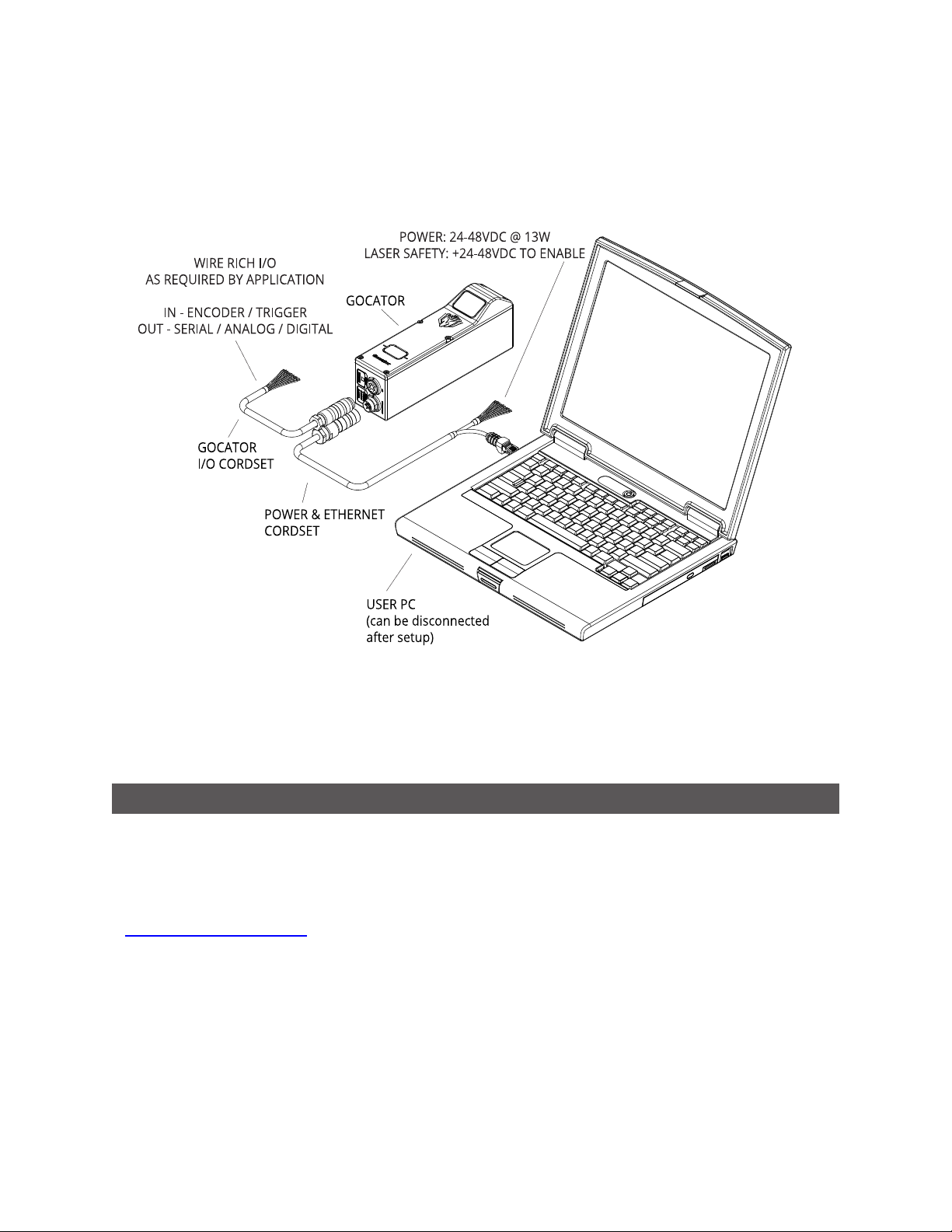
Standalone System
Standalone systems are typically used when only a single Gocator sensorscanner is required. The
sensorscanner can be connected to a computer's Ethernet port for setup and can also be connected to
devices such as encoders, photocells, or PLCs.
Gocator Line Profile Sensors: User Manual
Getting Started • 27
Dual-Sensor System
In a dual-sensor system, two Gocator sensors work together to perform profiling and output the
combined results. The controlling sensor is referred to as the Main sensor, and the other sensor is
referred to as the Buddy sensor. Gocator's software recognizes three installation orientations: Opposite,
Wide, and Reverse.
A Master network controller (excluding Master 100) must be used to connect two sensors in a dual-
sensor system. Gocator Power and Ethernet to Master cordsets areused to connect sensors to the
Master.
Gocator Line Profile Sensors: User Manual
Getting Started • 28

Multi-Sensor System
A Master network controller (excluding Master 100) can be used to connect two or more sensors into a
multi-sensor system. Gocator Master cordsets are used to connect the sensors to a Master. The Master
provides a single point of connection for power, safety, encoder, and digital inputs. A Master
400/800/1200/2400 can beused to ensure that the scan timing is precisely synchronized across
sensors. Sensors and client computers communicate viaan Ethernet switch (1 Gigabit/s recommended).
Master networking hardware does not support digital, serial, or analog output.
Gocator Line Profile Sensors: User Manual
Getting Started • 29

Installation
The following sections provide grounding, mounting, and orientation information.
Mounting
Sensors should be mounted using a model-dependent number of screws. Some models also provide the
option to mount using bolts in through-body holes. Refer to the dimension drawings of the sensors in
Specifications on page 583 for the appropriate screw diameter, pitch, and length, and bolt hole diameter.
Proper care should be taken in order to ensure that the internal threads are not damaged from
cross-threading or improper insertion of screws.
With the exception of Gocator 2880, sensors should not be installed near objects that might occlude a
camera's view of the laser. (Gocator 2880 is specifically designed to compensate for occlusions.)
Sensors should not be installed near surfaces that might create unanticipated laser reflections.
Gocator Line Profile Sensors: User Manual
Getting Started • 30

The sensor must be heat sunk through the frame it is mounted to. When a sensor is properly
heat sunk, the difference between ambient temperature and the temperature reported in the
sensor's health channel is less than 15° C.
Gocator sensors are high-accuracy devices. The temperature of all of its components must be
in equilibrium. When the sensor is powered up, a warm-up time of at least one hour is required
to reach a consistent spread of temperature within the sensor.
Orientations
The examples below illustrate the possible mounting orientations for standalone and dual-sensor
systems.
See Layout on page 84 for more information on orientations.
Standalone Orientations
Gocator Line Profile Sensors: User Manual
Single sensor above conveyor
Getting Started • 31

Single sensor on robot arm
Dual-Sensor System Orientations:
Side-by-side for wide-area measurement (Wide) Main must be on the left side (when
looking into the connector)
of the Buddy (Wide)
Gocator Line Profile Sensors: User Manual
Getting Started • 32

Above/below for two-sided measurement (Opposite) Main must be on the top
with Buddy on the bottom (Opposite)
For more information on setting up a dual-sensor system, see
http://lmi3d.com/sites/default/files/APPNOTE_Gocator_2300_Gocator_4.x_Dual_Sensor_Setup_
Guide.pdf.
Grounding
Components of a Gocator system should be properly grounded.
Gocator
Gocators should be grounded to the earth/chassis through their housings and through the grounding
shield of the Power I/O cordset. Gocator sensors have been designed to provide adequate grounding
through the use of M5 x 0.8 pitch mounting screws. Always check grounding with a multi-meter to
ensure electrical continuity between the mounting frame and the Gocator's connectors.
The frame or electrical cabinet that the Gocator is mounted to must be connected to earth ground.
Recommended Practices for Cordsets
If you need to minimize interference with other equipment, you can ground the Power & Ethernet or the
Power & Ethernet to Master cordset (depending on which cordset you are using) by terminating the
shield of the cordset before the split. The most effective grounding method is to use a 360-degree
clamp.
Gocator Line Profile Sensors: User Manual
Getting Started • 33

To terminate the cordset's shield:
1. Expose the cordset's braided shield by cutting
the plastic jacket before the point where the
cordset splits.
2. Install a 360-degree ground clamp.
Master Network Controllers
The rack mount brackets provided with all Masters are designed to provide adequate grounding through
the use of star washers. Always check grounding with a multi-meter by ensuring electrical continuity
between the mounting frame and RJ45 connectors on the front.
When using the rack mount brackets, you must connect the frame or electrical cabinet to which
the Master is mounted to earth ground.
You must check electrical continuity between the mounting frame and RJ45 connectors on the
front using a multi-meter.
If you are mounting Master 810 or 2410 using the provided DIN rail mount adapters, you must ground
the Master directly; for more information, see Grounding When Using a DIN Rail (Master 810/2410) on the
next page.
Gocator Line Profile Sensors: User Manual
Getting Started • 34

Grounding When Using a DIN Rail (Master 810/2410)
If you are using DIN rail adapters instead of the rack mount brackets, you must ensure that the Master is
properly grounded by connecting a ground cable to one of the holes indicated below. The holes accept
M4x5 screws.
Installing DIN Rail Clips: Master 810 or 2410
You can mount the Master 810 and 2410 using the included DINrail mounting clips with M4x8 flat
socket cap screws. The following DINrail clips (DINM12-RC) are included:
To install the DINrail clips:
1. Remove the 1Urack mount brackets.
2. Locate the DINrail mounting holes on the back of the Master (see below).
Master 810:
Gocator Line Profile Sensors: User Manual
Getting Started • 35

Master 2410:
3. Attach each of the two DINrail mount clips to the back of the Master using an M4x8 flat socket cap screw for
each one.
The following illustration shows the installation of clips on a Master 810 for horizontal mounting:
Ensure that there is enough clearance around the Master for cabling.
Configuring Master 810
If you are using Master 810 with an encoder that runs at a quadrature frequency higher than 300 kHz,
you must use the device's divider DIP switches to limit the incoming frequency to 300 kHz.
Master 810 supports up to a maximum incoming encoder quadrature frequency of 6.5 MHz.
The DIP switches are located on the rear of the device.
Gocator Line Profile Sensors: User Manual
Getting Started • 36

Switches 5 to 8 are reserved for future use.
This section describes how to set the DIP switches on Master 810 to do the following:
l Set the divider so that the quadrature frequency of the connected encoder is compatible with the
Master.
l Set the debounce period to accommodate faster encoders.
Setting the Divider
To set the divider, you use switches 1 to 3. To determine which divider to use, use the following formula:
Output Quadrature Frequency = Input Quadrature Frequency / Divider
In the formula, use the quadrature frequency of the encoder (for more information, see Encoder
Quadrature Frequency below) and a divider from the following table so that the Output Quadrature
Frequency is no more than 300 kHz.
Divider Switch 1 Switch 2 Switch 3
1 OFF OFF OFF
2 ON OFF OFF
4 OFF ON OFF
8 ON ON OFF
16 OFF OFF ON
32 ON OFF ON
64 OFF ON ON
128 ON ON ON
The divider works on debounced encoder signals. For more information, see Setting the
Debounce Period on the next page.
Encoder Quadrature Frequency
Encoder quadrature frequency is defined as illustrated in the following diagram. It is the frequency of
encoder ticks. This may also be referred as the native encoder rate.
Gocator Line Profile Sensors: User Manual
Getting Started • 37

You must use a quadrature frequency when determining which divider to use (see Setting the Divider on
the previous page). Consult the datasheet of the encoder you are using to determineits quadrature
frequency.
Some encoders may be specified in terms of encoder signal frequency (or period). In this case,
convert the signal frequency to quadrature frequency by multiplying the signal frequency by 4.
Setting the Debounce Period
If the quadrature frequency of the encoder you are using is greater than 3 MHz, you must set the
debounce period to “short.” Otherwise, set the debounce period to “long.”
You use switch 4 to set the debounce period.
Debounce period Switch 4
short debounce ON
long debounce OFF
Rut-Scanning System Setup
The following sections describe how to set up a Gocator 2375 rut-scanning system.
Layout
The Gocator 2375 sensor is designed to cover a scan width of up to 4.2 m by using 8 sensors mounted
in parallel.
Gocator Line Profile Sensors: User Manual
Getting Started • 38

The diagram above shows the clearance distanceand measurement range required in a typical setup.
Use the specification estimator (Gocator-2375_Specification_Estimator.xlsx) to calculate the X and Z
resolution of the sensors with different combinations of clearance distance and measurement range.
System Setup
A typical Gocator 2375 system is set up as a multi-sensor system. Thesensors are powered using a
Master network controller (excluding Master 100).
To connect a Gocator 2375:
1. Connect the Power and Ethernet to Master cordset to the Power/LAN connector on the sensor.
Gocator Line Profile Sensors: User Manual
Getting Started • 39

2. Connect the RJ45 jack labeled Power to an unused port on the Master.
3. Connect the RJ45 jack labeled Ethernet to an unused port on the Master.
4. Repeat the steps above for each sensor.
See Master 400/800 on page 627 and Master 1200/2400 on page 640 for more information on how to
install a Master.
Software Configuration
Each sensor is shipped with a default IP address of 192.168.1.10. Before you add a sensor to a multisensor system, its firmware version must match that of the other sensors, and its IP address must be
unique.
To configure a Gocator 2375 for the first time:
1. Set up the sensor’s IP address.
a. Follow the steps in Running a Standalone Sensor System on page 44.
b. Make sure that there is no other sensor in the network with the IP address 192.168.1.10.
2. Upgrade the firmware.
a. Follow the steps in Firmware Upgrade on page 99.
3. Set up profiling parameters.
a. Follow the steps in Scan Setup and Alignment on page 103 to set up profiling parameters. Typically,
trigger, active area, and exposure will need to be adjusted.
System Operation
An isolated layout should be used. Under this layout, each sensor can be independently controlled by
the SDK. The following application notes explain how to operate a multi-sensor system using the SDK.
APPNOTE_Gocator_4.x_Multi_Sensor_Guide.zip
Explains how to use the SDK to create a multi-sensor system, and multiplex their timing.
Gocator-2000-2300_appnote_multi-sensor-alignment-calibration.zip
Explains how to use the SDK to perform alignment calibration of a multi-sensor system.
You can find the app notes under the How-to category in LMI's online Gocator resources.
Example code is included with both of the application notes above.
Gocator Line Profile Sensors: User Manual
Getting Started • 40

Network Setup
The following sections provide procedures for client PCand Gocator network setup.
DHCP is not recommended for Gocator sensors. If you choose to use DHCP, the DHCPserver
should try to preserve IPaddresses. Ideally, you should use static IP address assignment (by
MAC address) to do this.
Client Setup
To connect to a sensor from a client PC, you must ensure the client's network card is properly
configured.
Sensors are shipped with the following default network configuration:
Setting Default
DHCP Disabled
IP Address 192.168.1.10
Subnet Mask 255.255.255.0
Gateway 0.0.0.0
All Gocator sensors are configured to 192.168.1.10 as the default IP address. For a dual-sensor
system, the Main and Buddy sensors must be assigned unique addresses before they can be used
on the same network. Before proceeding, connect the Main and Buddy sensors one at a time (to
avoid an address conflict) and use the steps in See Running a Dual-Sensor System on page 45 to
assign each sensor a unique address.
Gocator Line Profile Sensors: User Manual
Getting Started • 41

To connect to a sensor for the first time:
1. Connect cables and apply power.
Sensor cabling is illustrated in System
Overview on page 27.
2. Change the client PC's network
settings.
Windows 7
a. Open the Control Panel, select
Network and Sharing Center,
and then click Change Adapter
Settings.
b. Right-click the network connection
you want to modify, and then click
Properties.
c. On the Networking tab, click
Internet Protocol Version 4
(TCP/IPv4), and then click
Properties.
d. Select the Use the following IP
address option.
e. Enter IP Address "192.168.1.5"
and Subnet Mask "255.255.255.0",
then click OK.
Gocator Line Profile Sensors: User Manual
Getting Started • 42

Mac OS X v10.6
a. Open the Network pane in
System Preferences and select
Ethernet.
b. Set Configure to Manually.
c. Enter IP Address "192.168.1.5"
and Subnet Mask "255.255.255.0",
then click Apply.
See Troubleshooting on page 581 if you experience any problems while attempting to establish a
connection to the sensor.
Gocator Line Profile Sensors: User Manual
Getting Started • 43

Gocator Setup
The Gocator is shipped with a default configuration that will produce laser profiles for most targets.
The following sections describe how to set up a standalone sensor system and a dual-sensor system for
operations. After you have completed the setup, you can perform laser profiling to verify basic sensor
operation.
Running a Standalone Sensor System
To configure a standalone sensor system:
1. Power up the sensor.
The power indicator (blue) should turn on immediately.
2. Enter the sensor's IP address (192.168.1.10) in a web
browser.
The Gocator interface loads.
If a password has been set, you will be prompted to
provide it and then log in.
3. Go to the Manage page.
4. Ensure that Replay mode is off (the slider is set to the left).
Replay mode disables measurements.
5. Ensure that the Laser Safety Switch is enabled or the
Laser Safety input is high.
6. Go to the Scan page.
7. Observe the profile in the data viewer
8. Press the Start button or the Snapshot on the Toolbar to
start the sensor.
The Start button is used to run sensors continuously.
The Snapshot button is used to trigger the capture of a
single profile.
Standalone
Master 400/800/1200/2400
Gocator Line Profile Sensors: User Manual
Getting Started • 44

Master 810/2410
9. Move a target into the laser plane.
If a target object is within the sensor's measurement
range, the data viewer will display the shape of the target,
and the sensor's range indicator will illuminate.
If you cannot see the laser, or if a profile is not displayed
in the Data Viewer, see Troubleshooting on page 581.
10. Press the Stop button.
The laser should turn off.
Running a Dual-Sensor System
All sensors areshipped with a default IP address of 192.168.1.10. Ethernet networks require a unique IP
address for each device, so you must set up a unique address for each sensor.
To configure a dual-sensor system:
1. Turn off the sensors and unplug the Ethernet network
connection of the Main sensor.
All sensors are shipped with a default IP address of
192.168.1.10. Ethernet networks require a unique IP
address for each device. Skip step 1 to 3 if the Buddy
sensor's IP address is already set up with an unique
address.
2. Power up the Buddy sensor.
The power LED (blue) of the Buddy sensor should turn on
immediately.
3. Enter the sensor's IP address 192.168.1.10 in a web
browser.
Gocator Line Profile Sensors: User Manual
Getting Started • 45

The Gocator interface loads.
4. Go to the Manage Page.
5. Modify the IP address to 192.168.1.11 in the Networking
category and click the Save button.
When you click the Save button, you will be prompted to
confirm your selection.
6. Turn off the sensors, re-connect the Main sensor's
Ethernet connection and power-cycle the sensors.
After changing network configuration, the sensors must
be reset or power-cycled before the change will take
effect.
7. Enter the sensor's IP address 192.168.1.10 in a web
browser.
The Gocator interface loads.
8. Select the Manage page.
9. Go to Manage page, Sensor System panel, and select the
Visible Sensors panel.
The serial number of the Buddy sensor is listed in the
Available Sensors panel.
10. Select the Buddy sensor and click the Assign button.
The Buddy sensor will be assigned to the Main sensor and
Gocator Line Profile Sensors: User Manual
Getting Started • 46

its status will be updated in the System panel.
The firmware on Main and Buddy sensors must be the
same for Buddy assignment to be successful. If the
firmware is different, connect the Main and Buddy sensor
one at a time and follow the steps in Firmware Upgrade on
page 99 to upgrade the sensors.
11. Ensure that the Laser Safety Switch is enabled or the
Laser Safety input is high.
12. Ensure that Replay mode is off (the slider is set to the
left).
Master 400/800/1200/2400
Master 810/2410
13. Go to the the Scan page.
14. Press the Start or the Snapshot button on the Toolbarto
start the sensors.
The Start button is used to run sensors continuously,
while the Snapshot button is used to trigger a single
profile.
15. Move a target into the laser plane.
If a target object is within the sensor's measurement
range, the data viewer will display the shape of the target,
and the sensor's range indicator will illuminate.
If you cannot see the laser, or if a profile is not displayed
in the Data Viewer, see Troubleshooting on page 581.
16. Press the Stop button if you used the Start button to start
the sensors.
The laser should turn off.
Gocator Line Profile Sensors: User Manual
Getting Started • 47

Next Steps
After you complete the steps in this section, the Gocator measurement system is ready to be configured
for an application using the software interface. The interfaceis explained in the following sections:
Management and Maintenance (page 81)
Contains settings for sensor system layout, network, motion and alignment, handling jobs, and sensor
maintenance.
Scan Setup and Alignment (page 103)
Contains settings for scan mode, trigger source, detailed sensor configuration, and performing
alignment.
Models (page 159)
Contains settings for creating part matching models and sections.
Measurement (page 180)
Contains built-in measurement tools and their settings.
Output (page 318)
Contains settings for configuring output protocols used to communicate measurements to external
devices.
Dashboard (page 330)
Provides monitoring of measurement statistics and sensor health.
Toolbar (page 70)
Controls sensor operation, manages jobs, and replays recorded measurement data.
Gocator Line Profile Sensors: User Manual
Getting Started • 48

How Gocator Works
The following sections provide an overview of how Gocator acquires and produces data, detects and
measures parts, and controls devices such as PLCs. Some of these concepts are important for
understanding how you should mount sensors and configure settings such as active area.
You can use the Gocator Accelerator to speed up processing of data. For more information, see
Gocator Accelerator on page 349.
3D Acquisition
After a Gocator system has been set up and is running, it is ready to start capturing 3D data.
Gocator laser profile sensors project a laser line onto the target.
The sensor's camera views the laser line on the target from an angle and captures the reflection of the
laser light off the target. The camera captures a single 3D profile—a slice, in a sense—for each camera
exposure. The reflected laser light falls on the camera at different positions, depending on the distance
of the target from the sensor. The sensor’s laser emitter, its camera, and the target form a triangle.
Gocator uses the known distance between the laser emitter and the camera, and two known angles—
one of which depends on the position of the laser light on the camera—to calculate the distance from
the sensor to the target. This translates to the height of the target. This method of calculating distance is
called laser triangulation.
Gocator Line Profile Sensors: User Manual
49

Target objects typically move on a conveyor belt or other transportation mechanism under a sensor
mounted in a fixed position. Sensors can also bemounted on robot arms and moved over the target. In
both cases, the sensor captures a series of 3D profiles, building up a full scan of the target. Sensor speed
and required exposure time to measure the target are typically critical factors in applications with line
profilesensors.
Gocator sensors are always pre-calibrated to deliver 3D data in engineering units throughout
their measurement range.
Clearance Distance, Field of Viewand Measurement Range
Clearance distance (CD), field of view (FOV),and measurement range (MR)are important concepts for
understanding the setup of a Gocator sensor and for understanding results.
Clearance distance – The minimum distance from the sensor that a target can be scanned and
measured. A target closer than this distance will result in invalid data.
Measurement range – The vertical distance, starting at the end of the clearance distance, in which
targets can be scanned and measured. Targets beyond the measurement range will result in invalid data.
Field of view –The width on the X axis along the measurement range. At the far end of the
measurement range, the field of view is wider, but the X resolution and Zresolution are lower. At the
near end, the field of view is narrower, but the X resolution is higher. When resolution is critical, if
possible, place the target closer to the near end. (For more information on the relation between target
distance and resolution, see
Gocator Line Profile Sensors: User Manual
How Gocator Works • 50

Resolution and Accuracy
The following sections describe X Resolution, ZResolution, and ZLinearity. These terms are used in the
Gocator datasheets to describe the measurement capabilities of the sensors.
X Resolution
X resolution is the horizontal distance between each measurement point along the laser line. This
specification is based on the number of camera columns used to cover the field of view (FOV) at a
particular measurement range.
Because the FOV is trapezoidal (shown in red, below), the distance between points is closer at the near
range than at the far range. This is reflected in the Gocator data sheet as the two numbers quoted for X
resolution.
X Resolution is important for understanding how accurately width on a target can be measured.
When the Gocator runs in Profile mode and Uniform Spacing is enabled, the 3D data is
resampled to an X interval that is different from the raw camera resolution. For more
information, see Spacing (Data Resampling) on page 59.
Gocator Line Profile Sensors: User Manual
How Gocator Works • 51

Z Resolution
Z Resolution gives an indication of the smallest detectable height difference at each point, or how
accurately height on a target can be measured. Variability of height measurements at any given moment,
in each individual 3D point, with the target at a fixed position, limits Z resolution. This variability is
caused by camera and sensor electronics.
Like X resolution, Z resolution is better closer to the sensor. This is reflected in the Gocator data sheet as
the two numbers quoted for Z resolution.
Z Linearity
Z linearity is the difference between the actual distance to the target and the measured distance to the
target, throughout the measurement range. Z linearity gives an indication of the sensor's ability to
measure absolute distance.
Gocator Line Profile Sensors: User Manual
How Gocator Works • 52

Z linearity is expressed in the Gocator data sheet as a percentage of the total measurement range.
Gocator Line Profile Sensors: User Manual
How Gocator Works • 53

Profile Output
Gocator represents a profile as a series of ranges, with each range representing the distance from the
origin. Each range contains a height (on the Z axis) and a position (on the X axis) in the sensor's field of
view.
Coordinate Systems
Range data is reported in one of three coordinate systems, which generally depends on the alignment
state of the sensor. Sensor coordinates are used for unaligned sensors, whereas system coordinates are
used for aligned sensors. Part data can optionally be reported using a coordinate system relative to the
part itself. These systems are described below.
Sensor Coordinates
Unaligned sensors use the coordinate system shown below.
The measurement range (MR) is along the Z axis. Values increasetoward the sensor. The sensor’s field of
view (FOV) is along the X axis. The origin is at the center of the MR and FOV.
In Surface data, the Y axis represents the relative position of the part in the direction of travel. Y position
increases as the object moves forward (increasing encoder position). The image below represents a lefthanded coordinate system.
Gocator Line Profile Sensors: User Manual
How Gocator Works • 54

The mounting direction, relative to the direction of travel, can be set in Gocator using either the Normal
or Reverse layout. For more information, see Layout on page 84.
System Coordinates
Aligning sensors adjusts the coordinate system in relation to sensor coordinates using transformations
(offsets along the axes and rotations around the axes).
Alignment is used with a single sensor to compensate for mounting misalignment and to set a zero
reference, such as a conveyor belt surface.
Alignment is also used to set a common coordinate system for multi-sensor systems. That is, scan data
and measurements from the sensors are expressed in a unified coordinate system.
Gocator Line Profile Sensors: User Manual
How Gocator Works • 55

System coordinates are aligned so that the system X axis is parallel to the alignment target surface. The
system Z origin is set to the base of the alignment target object.
In both cases, alignment determines the offsets in X and Z.
Offsets can also be determined along the Yaxis. This allows setting up a staggered layout in multi-sensor
systems. This is especially useful in side-by-side mounting scenarios, as it provides full coverage for
models such as Gocator 2410 and Gocator 2420.
As with sensor coordinates, Y position increases as the object moves forward (increasing encoder
position). Gocator defines the travel direction to be forward when the object travels from the laser’s end
to the camera end of the sensor.
Alignment also determines the Y Angle (angle on the X–Z plane, around the Yaxis) needed to align sensor
data. This is also sometimes called roll correction.
Gocator Line Profile Sensors: User Manual
How Gocator Works • 56

Y Angle
Y angle is positive when rotating from positive X to positive Z axis.
Finally, tilt can be determined around the X and the Zaxis, which compensates for the angle in height
measurements. These are sometimes called pitch correction and yaw correction, respectively. Rotation
around the X axis often used for specular mounting.
X Angle
Z Angle
X angle is positive when rotating from positive Y to positive Z. Z angle is positive when rotating from
positive X to positive Y.
Gocator Line Profile Sensors: User Manual
How Gocator Works • 57

When applying the transformations, the object is first rotated around X, then Y, and then Z, and then the
offsets are applied.
The adjustments resulting from alignment are called transformations and are displayed in Sensor panel
on the Scan page. For more information on transformations in the web interface, see Transformations
on page 115.
For more information on aligning sensors, see Alignment on page 125.
Part and Section Coordinates
When you work with parts or sections extracted from scan data, a different coordinate system is
available.
Part data can be expressed in aligned system coordinates or unaligned sensor coordinates, depending
on the alignment state of the sensor. Part data can also be represented in part coordinates: data and
measurement results are in a coordinate system that places the X and Yorigins at the center of the part.
The Z origin is at the surface surrounding the alignment target.
The Frame of Reference setting, in the Part Detection panel on the Scan page, controls
whether part data is recorded using sensor/system coordinates or part coordinates.
Sections are always represented in a coordinate system similar to part coordinates: the X origin is always
at the center of the extracted profile, and the Z origin is at the bottom of the alignment target (or in the
center of the measurement range if the sensor is unaligned).
Switching between Coordinate Systems
In many situations, when working with part data that has been recorded with Frame of Reference set
to Part or section data, it is useful to have access to the "real-world"coordinates, rather than part- or
section-relative coordinates. Gocator provides special "global"measurements, in the Bounding Box
tools, that you can use in Gocator scripts to convert from part or section coordinates to sensor/system
coordinates.
Gocator Line Profile Sensors: User Manual
How Gocator Works • 58

For more information, see the ProfileBounding Box tool or the Surface Bounding Box tool, and the
Script tool.
Spacing (Data Resampling)
Data produced in Profile mode is available in two formats: with and without uniform spacing. Uniform
spacing is enabled in the Scan Mode panel, on the Scan page.
When uniform spacing is enabled, the ranges that make up a profile are resampled so that the spacing is
uniform along the laser line (X axis). The resampling divides the X axis into fixed size "bins." Profile points
that fall into the same bin are combined into a single range value (Z). The size of the spacing interval is
set under the Spacing tab in the Sensor panel on Scan page.
Resampling to uniform spacing reduces the complexity for downstream algorithms to process the profile
data from the Gocator, but places a higher processing load on the sensor's CPU.
When uniform spacing is not enabled, no processing is required on the sensor. This frees up processing
resources in the Gocator, but usually requires more complicated processing on the client side. Ranges in
this case are reported in (X, Z) coordinate pairs.
Most built-in measurement tools in the Gocator in Profile mode operate on profiles with uniform
spacing. Alimited number of tools can operate on profiles without uniform spacing. For more
information on the profile tools, see Profile Measurement on page 202.
A drawback of uniform spacing is that if sensors are angled to scan the sides of a target, data on the
"verticals"is lost because points falling in the same "bin"are combined. When Uniform Spacing is
disabled, however, all points are preserved on the sides. In this case, the data can be processed by the
subset of tools that work on profiles without uniform spacing. Alternatively, the data can be processed
externally using the SDK.
When uniform spacing is enabled, in the Ethernet output, only the range values (Z) are reported
and the X positions can be reconstructed through the array index at the receiving end (the
client). For more information on Ethernet output, see Ethernet Output on page 319.
For information on enabling uniform spacing, see Scan Modes on page 104.
Gocator Line Profile Sensors: User Manual
How Gocator Works • 59

Data Generation and Processing
After scanning a target, Gocator can process the scan data to allow the use of more sophisticated
measurement tools. This section describes the following concepts:
l Surface generation
l Part detection
l Sectioning
Surface Generation
Gocator laser profile sensors create a single profile with each exposure. These sensors can combine a
series of profiles gathered as a target moves under the sensor to generate a height map, or surface, of
the entire target.
For more information, see Surface Generation on page 134.
Part Detection
After Gocator has generated a surface by combining single exposures into larger pieces of data, the
firmware can isolate discrete parts on a generated surface into separate scans representing parts.
Gocator can then perform measurements on these isolated parts.
Gocator Line Profile Sensors: User Manual
How Gocator Works • 60

Part detection is useful when measurements on individual parts are needed and for robotic pick and
place applications.
For more information on part detection, see Part Detection on page 137.
Sectioning
In Surface mode, Gocator can also extract a profile from a surface or part using a line you define on that
surface or part. The resulting profile is called a “section.” A section can have any orientation on the
surface, but its profile is parallel to the Z axis.
You can use most of Gocator's profile measurement tools on a section, letting you perform
measurements that are not possible with surface measurement tools.
For more information on sections, see Sections on page 174.
Part Matching
Gocator can match scanned parts to the edges of a model based on a previously scanned part (see Using
Edge Detection on page 161) or to the dimensions of a fitted bounding box or ellipse that encapsulate
the model (seeUsing Bounding Box and Ellipse on page 170). When parts match, Gocator can rotate
scans so that they are all oriented in the sameway. This allows measurement tools to be applied
consistently to parts, regardless of the orientation of the part you are trying to match.
Gocator Line Profile Sensors: User Manual
How Gocator Works • 61

Measurement and Anchoring
After Gocator scans a target and, optionally, further processes the data, the sensor is ready to take
measurements on the scan data.
Gocator provides several measurement tools, each of which provides a set of individual measurements,
giving you dozens of measurements ideal for a wide variety of applications to choose from. The
configured measurements start returning pass/fail decisions, as well as the actual measured values,
which are then sent over the enabled output channels to control devices such as PLCs, which can in turn
control ejection or sorting mechanisms. (For moreinformation on measurements and configuring
measurements, see Measurement on page 180.)
You can create custom measurement tools that run your own algorithms. For more information,
see GDK on page 544.
A part's position can vary on a transport system. To compensate for this variation, Gocator can anchor a
measurement to the positional measurement (X, Y, or Z) or Z angle of an easily detectable feature, such
as the edge of a part. The calculated offset between the two ensures that the anchored measurement
will always be properly positioned on different parts.
If combined with the matching and rotation capabilities of part matching, anchoring accounts for most
sources of variation in part position and orientation and, consequently, avoids many measurement
errors. For more information on anchoring, see Measurement Anchoring on page 194.
Output and Digital Tracking
After Gocator has scanned and measured parts, the last step in the operation flow is to output the
results and/or measurements.
One of the main functions of Gocator sensors is to produce pass/fail decisions, and then control
something based on that decision. Typically, this involves rejecting a part through an eject gate, but it can
Gocator Line Profile Sensors: User Manual
How Gocator Works • 62

also involve making decisions on good, but different, parts. This is described as “output” in Gocator.
Gocator supports the following output types:
l Ethernet (which provides industry-standard protocols such as Modbus, EtherNet/IP, and ASCII, in
addition to the Gocator protocol)
l Digital
l Analog
l Serial interfaces
An important concept is digital output tracking. Production lines can place an ejection or sorting
mechanism at different distances from where the sensor scans the target. For this reason, Gocator lets
you schedule a delayed decision over the digital interfaces. Because the conveyor system on a typical
production line will use an encoder or have a known, constant speed, targets can effectively be “tracked”
or "tagged."Gocator will know when a defective part has traveled far enough and trigger a PLC to
activate an ejection/sorting mechanism at the correct moment. For more information on digital output
tracking, see Digital Output on page 323.
Gocator Line Profile Sensors: User Manual
How Gocator Works • 63

Gocator Web Interface
The following sections describe the Gocator web interface.
Unblocking Flash
The current version of the Gocator web interface uses the Adobe Flash software platform. Many
browsers currently block Adobe Flash by default due to new web standards and security concerns.
If you have issues running the Gocator web interface in your browser, the instructions provided below
should help you get up and running. If you continue to have issues, try using a different browser or
contact LMI.
LMIis currently working to move the Gocator web interface off Adobe Flash to a WebGL-based
interface in an upcoming release.
Google Chrome
Recent versions of Google Chrome aggressively block Flash, even ignoring site exceptions. Use the
following instructions to unblock Flash in Chrome 61 and later.
To unblock Flash in Google Chrome:
1. In the Google Chrome browser address bar, type chrome://settings/content/flash and press Enter.
2. In the settings page that displays, enable Allow sites to run Flash and disable Ask first.
3. Restart Chrome by clicking Relaunch Now.
Gocator Line Profile Sensors: User Manual
64

4. As the Gocator interface is loading, click the Plugins Blocked icon ( ) to the right of the address bar and
click "Allow Flash content this time."
You must perform this step each time you launch the Gocator interface in Google Chrome.
Internet Explorer
Use the following steps to unblock Flash in Internet Explorer 11.
To unblock Flash in Internet Explorer:
1. In Internet Explorer, click the settings icon ( ) and choose the Manage add-ons item from the drop-down
menu.
2. In the Manage add-ons dialog, scrolll down to the Shockwave Flash Object extension and click on it.
Gocator Line Profile Sensors: User Manual
Gocator Web Interface • 65

If you don't see Shockwave Flash Object in the list, you may need to choose All add-onsin the Show dropdown.
3. In the dialog, click Enable.
Firefox
Use the following steps to unblock Flash in Firefox.
To unblock Flash in Firefox:
1. In Firefox, click the menu icon ( ) and then click the Add-ons icon from the drop-down menu.
Gocator Line Profile Sensors: User Manual
Gocator Web Interface • 66

2. In the Add-ons Manager, click the Plugins category to the left and choose Always Activate next to
Shockwave Flash.
Microsoft Edge
Use the following steps to unblock Flash in Microsoft Edge.
To unblock Flash in Microsoft Edge:
1. In Microsoft Edge, click the menu icon ( ) and then choose the Settings item from the drop-down menu.
Gocator Line Profile Sensors: User Manual
Gocator Web Interface • 67

2. In the Settings drop-down, scroll down and click View advanced settings.
3. Under Advanced settings, set Use Adobe Flash Player to On.
Gocator Line Profile Sensors: User Manual
Gocator Web Interface • 68

User Interface Overview
Gocator sensors are configured by connecting to the Main sensor with a web browser. The Gocator web
interface is shown below.
Gocator Line Profile Sensors: User Manual
Gocator Web Interface • 69

Element Description
1 Manage page Contains settings for sensor system layout, network, motion and
alignment, handling jobs, and sensor maintenance. See Management and
Maintenance on page 81.
2 Scan page Contains settings for scan mode, trigger source, d etailed sensor
configuration, and performing alignment. See Scan Setup and Alignment on
page 103.
3 Model page Lets you set up sections and part matching. See Models on page 159
4 Measure page Contains built-in measurement tools and their settings. See Measurement
on page 180.
5 Output page Contains settings for configuring output protocols used to communicate
measurements to external devices. See Output on page 318.
6 Dashboard page Provides monitoring of measurement statistics and sensor health. See
Dashboard on page 330.
7 CPULoad and Sp eed Provides important sensor performance metrics. See Metrics Area on page
78.
8 Toolbar Controls sensor operation, manages jobs, and filters and replays
recorded measurement data. See Toolbar below.
9 Configuration area Provides controls to configure scan and measurement tool settings.
10
11
Data viewer
Status bar
Displays sensor data, tool setup controls, and measurements. See Data
Viewer on page 144 for its use when the Scan page is active and on page
181 for its use when the Measure page is active.
Displays log messages from the sensor (errors, warnings, and other
information) and frame information, and lets you switch the interface
language. For more information,
Toolbar
The toolbar is used for performing operations such as managing jobs, working with replay data, and
starting and stopping the sensor.
Element Description
1 Job controls For saving and loading jobs.
2 Replay data controls For downloading, uploading, and exporting recorded data.
3 Sensor operation / replay control Use the sensor operation controls to start sensors, enable and
filter recording, and control recorded data.
Gocator Line Profile Sensors: User Manual
Gocator Web Interface • 70

Creating, Saving and Loading Jobs (Settings)
A Gocator can store several hundred jobs. Being able to switch between jobs is useful when a Gocator is
used with different constraints during separate production runs. For example, width decision minimum
and maximum values might allow greater variation during one production run of a part, but might allow
less variation during another production run, depending on the desired grade of the part.
Most of the settings that can be changed in the Gocator's web interface, such as the ones in the
Manage, Measure, and Output pages, are temporary until saved in a job file. Each sensor can have
multiple job files. If there is a job file that is designated as the default, it will be loaded automatically
when the sensor is reset.
When you change sensor settings using the Gocator web interface in the emulator, some changes are
saved automatically, while other changes are temporary until you save them manually. The following
table lists the types of information that can be saved in a sensor.
Setting Type Behavior
Job Most of the settings that can be changed in the Gocator's web interface, such as the ones
in the Manage, Measure, and Output pages, are temporary until saved in a job file.
Each sensor can have multiple job files. If there is a job file that is designated as the
default, it will be loaded automatically when the sensor is reset.
Alignment
Network Address Network address changes are saved when you click the
Alignment can either be fixed or dynamic, as controlled by the Alignment Reference
setting in Motion and Alignment in the Manage page.
Alignment is saved automatically at the end of the alignment procedure when
Alignment Reference is set to Fixed. When Alignment Reference is set to
Dynamic, however, you must manually save the job to save alignment.
button in
the
Manage
Save
page. The sensor must be reset before changes take effect.
Networking
on
The job drop-down list in the toolbar shows the jobs stored in the sensor. The job that is currently active
is listed at the top. The job name will be marked with "[unsaved]" to indicate any unsaved changes.
To create a job:
1. Choose [New] in the job drop-down list and type a name for the job.
2. Click the Save button or press Enter to save the job.
The job is saved to sensor storage using the name you provided. Saving a job automatically sets it as
the default, that is, the job loaded when then sensor is restarted.
To save a job:
l Click the Save button .
Gocator Line Profile Sensors: User Manual
Gocator Web Interface • 71

The job is saved to sensor storage. Saving a job automatically sets it as the default, that is, the job
loaded when then sensor is restarted.
To load (switch) jobs:
l Select an existing file name in the job drop-down list.
The job is activated. If there are any unsaved changes in the current job, you will be asked whether you want
to discard those changes.
You can perform other job management tasks—such as downloading job files from a sensor to a
computer, uploading job files to a sensor from a computer, and so on—in the Jobs panel in the Manage
page. See Jobs on page 95 for more information.
Recording, Playback, and Measurement Simulation
Gocator sensors can record and replay recorded scan data, and also simulate measurement tools on
recorded data. This feature is most often used for troubleshooting and fine-tuning measurements, but
can also be helpful during setup.
Recording and playback are controlled using the toolbar controls.
Recording and playback controls when replay is off
To record live data:
1. Toggle Replay mode off by setting the slider to the left in the Toolbar.
Replay mode disables measurements.
2. (Optional) Configure recording filtering.
For more information on recording filtering, see Recording Filtering on page 74.
3. Click the Record button to enable recording.
The center of the Record button turns red.
When recording is enabled (and replay is off), the sensor will store the most recent data as it runs.
Remember to disable recording if you no longer want to record live data. (Press the Record button
Gocator Line Profile Sensors: User Manual
Gocator Web Interface • 72

again to disable recording).
4. Press the Snapshot button or Start button.
The Snapshot button records a single frame. The Start button will run the sensor continuously and all
frames will be recorded, up to available memory. When the memory limit is reached, the oldest data
will be discarded.
Newly recorded data is appended to existing replay data unless the sensor job has been modified.
Playback controls when replay is on
To replay data:
1. Toggle Replay mode on by setting the slider to the right in the Toolbar.
The slider's background turns blue and a Replay Mode Enabled message is displayed.
2. Use the Replay slider or the Step Forward, Step Back, or Play buttons to review data.
The Step Forward and Step Back buttons move and the current replay location backward and forward
by a single frame, respectively.
The Play button advances the replay location continuously, animating the playback until the end of the
replay data.
The Stop button (replaces the Play button while playing) can be used to pause the replay at a particular
location.
The Replay slider (or Replay Position box) can be used to go to a specific replay frame.
To simulate measurements on replay data:
1. Toggle Replay mode on by setting the slider to the right in the Toolbar.
The slider's background turns blue and a Replay Mode Enabled message is displayed.
To change the mode, Replay Protection must be unchecked.
2. Go to the Measure page.
Modify settings for existing measurements, add new measurement tools, or delete measurement tools
as desired. For information on adding and configuring measurements, see Measurement on page 180.
Gocator Line Profile Sensors: User Manual
Gocator Web Interface • 73

3. Use the Replay Slider, Step Forward, Step Back, or Play button to simulate measurements.
Step or play through recorded data to execute the measurement tools on the recording.
Individual measurement values can be viewed directly in the data viewer. Statistics on the
measurements that have been simulated can be viewed in the Dashboard page; for more information
on the dashboard, see Dashboard on page 330.
To clear replay data:
1. Stop the sensor if it is running by clicking the Stop button.
2. Click the Clear Replay Data button .
Recording Filtering
Replay data is often used for troubleshooting. But replay data can contain thousands of frames, which
makes finding a specific frame to troubleshoot difficult. Recording filtering lets you choose which frames
Gocator records, based on one or more conditions, which makes it easier to find problems.
How Gocator treats conditions
Setting Description
Any Condition
All Conditions
Gocator records a frame when any condition is true.
Gocator only records a frame if all conditions are true.
Conditions
Setting Description
Any Measurement
Single Measurement
Gocator Line Profile Sensors: User Manual
Gocator records a frame when any measurement is in the state you select.
The following states are supported:
l pass
l fail or invalid
l fail and valid
l valid
l invalid
Gocator records a frame if the measurement with the IDyou specify in IDis in the state
you select. This setting supports the same states as the Any Measurement setting (see
above).
Gocator Web Interface • 74

Setting Description
Any Data
At/Above Threshold: Gocator records a frame if the number of valid points in the
frame is above the value you specify in Range Count Threshold.
Below Threshold: Gocator records a frame if the number of valid points is below the
threshold you specify.
In Surface mode, the number of valid points in the surface is compared to the
threshold, not any sections that may be defined.
To set recording filtering:
1. Make sure recording is enabled by clicking the Record button.
2. Click the Recording Filtering button .
3. In the Recording Filtering dialog, choose how Gocator treats conditions:
For information on the available settings, see How Gocator treats conditions on the previous page.
4. Configure the conditions that will cause Gocator to record a frame:
For information on the available settings, see Conditions on the previous page.
5. Click the "x"button or outside of the Recording Filtering dialog to close the dialog.
The recording filter icon turns green to show that recording filters have been set.
When you run the sensor, Gocator only records the frames that satisfy the conditions you have set.
Downloading, Uploading, and Exporting Replay Data
Replay data (recorded scan data) can bedownloaded from a Gocator to a client computer, or uploaded
from a client computer to a Gocator.
Data can also be exported from a Gocator to a client computer in order to process the data using thirdparty tools.
You can only upload replay data to the same sensor model that was used to create the data.
Replay data is not loaded or saved when you load or save jobs.
To download replay data:
1. Click the Download button .
2. In the File Download dialog, click Save.
Gocator Line Profile Sensors: User Manual
Gocator Web Interface • 75

3. In the Save As... dialog, choose a location, optionally change the name (keeping the .rec extension), and click
Save.
To upload replay data:
1. Click the Upload button .
The Upload menu appears.
2. In the Upload menu, choose one of the following:
l Upload:Unloads the current job and creates a new unsaved and untitled job from the content of the
replay data file.
l Upload and merge:Uploads the replay data and merges the data's associated job with the current
job. Specifically, the settings on the Scan page are overwritten, but all other settings of the current
job are preserved, including any measurements or models.
If you have unsaved changes in the current job, the firmware asks whether you want to discard the
changes.
3. Do one of the following:
l Click Discard to discard any unsaved changes.
l Click Cancel to return to the main window to save your changes.
4. If you clicked Discard, navigate to the replay data to upload from the client computer and click OK.
The replay data is loaded, and anew unsaved, untitled job is created.
Replay data can be exported using the CSVformat. If you have enabled Acquire Intensity in the Scan
Mode panel on the Scan page, the exported CSVfile includes intensity data.
Surface intensity data cannot be exported to the CSVformat. It can only be exported separately
as a bitmap.
Gocator Line Profile Sensors: User Manual
Gocator Web Interface • 76

To export replay data in the CSV format:
1. In the Scan Mode panel, switch to Profile or Surface.
2. Click the Export button and select All Data as CSV.
In Profile mode, all data in the record buffer is exported. In Surface mode, only data at the current
replay location is exported.
Use the playback control buttons to move to a different replay location; for information on playback,
see To replay data in Recording, Playback, and Measurement Simulation on page 72.
3. (Optional) Convert exported data to another format using the CSVConverter Tool. For information on
this tool, see CSV Converter Tool on page 575.
The decision values in the exported data depend on the current state of the job, not the state
during recording. For example, if you record data when a measurment returns a pass decision,
change the measurement's settings so that a fail decision is returned, and then export to CSV,
you will see a fail decision in the exported data.
Recorded intensity data can be exported to a bitmap (.BMP format). Acquire Intensity must be
checked in the Scan Mode panel while data was being recorded in order to export intensity data.
To export recorded intensity data to the BMP format:
l Click the Export button and select Intensity data as BMP.
Only the intensity data in the current replay location is exported.
Use the playback control buttons to move to a different replay location; for information on playback,
see To replay data in Recording, Playback, and Measurement Simulation on page 72.
Gocator Line Profile Sensors: User Manual
Gocator Web Interface • 77

To export video data to a BMPfile:
1. In the Scan Mode panel, switch to Video mode.
Use the playback control buttons to move to a different replay location; for information on playback,
see To replay data in Recording, Playback, and Measurement Simulation on page 72.
2. Click the Export button and select Video data as BMP.
Metrics Area
The Metrics area displays two important sensor performance metrics: CPU load and speed (current
frame rate).
The CPU bar in the Metrics panel (at the top of the interface) displays how much of the CPU is being
utilized. A warning symbol ( ) will appear next to the CPUbar if the sensor drops profiles because the
CPU is over-loaded.
CPUat 100%
The Speed bar displays the frame rate of the sensor. A warning symbol ( ) will appear next to it if
triggers (external input or encoder) are dropped because the external rate exceeds the maximum frame
rate.
Open the log for details on the warning. For more information on logs, see Log on the next page.
When a sensor is accelerated a "rocket"icon appears in the metrics area.
Data Viewer
The data viewer is displayed in both the Scan and the Measure pages, but displays different
information depending on which page is active.
When the Scan page is active, the data viewer displays sensor data and can be used to adjust the active
area and other settings. Depending on the selected operation mode (page 104), the data viewer can
display video images, profiles, sections, or surfaces. For details, see Data Viewer on page 144.
When the Measure page is active, the data viewer displays sensor data onto which representations of
measurement tools and their measurements are superimposed. For details, see Data Viewer on page
181.
Status Bar
The status bar lets you do the following:
Gocator Line Profile Sensors: User Manual
Gocator Web Interface • 78

l See sensor messages in the log.
l See frame information.
l Change the interface language.
l Switch to Quick Edit mode.
Log
The log, located at the bottom of the web interface, is a centralized location for all messages that the
Gocator displays, including warnings and errors.
A number indicates the number of unread messages:
To use the log:
1. Click on the Log open button at the bottom of the web interface.
2. Click on the appropriate tab for the information you need.
Frame Information
The area to the right of the status bar displays useful frame information, both when the sensor is
running and when viewing recorded data.
This information is especially useful when you have enabled recording filtering. If you look at a recording
playback, when you have enabled recording filtering, someframes can be excluded, resulting in variable
"gaps" in the data.
The following information is available:
Frame Index: Displays the index in the data buffer of the current frame. The value resets to 0 when the
sensor is restarted or when recording is enabled.
Master Time: Displays the recording time of the current frame, with respect to when the sensor was
started.
Encoder Index: Displays the encoder index of the current frame.
Timestamp: Displays the timestamp the current frame, in microseconds from when the sensor was
started.
Gocator Line Profile Sensors: User Manual
Gocator Web Interface • 79

To switch between types of frame information:
l Click the frame information area to switch to the next available type of information.
Interface Language
The language button on the right side of the status bar lets you change the languageof the Gocator
interface.
To use the log:
1. Click the language button at the bottom of the web interface.
2. Choose a language from the list.
The Gocator interface reloads on the page you were working in, displaying the page using the language you
chose. The sensor state is preserved.
Quick Edit Mode
When working with a very large number of measurement tools (for example, a few dozen) or a very
complex user-created GDK tool, you can switch to a "Quick Edit"mode to make configuration faster.
When this mode is enabled, the data viewer and measurement results are not refreshed after each
setting change. Also, when Quick Edit is enabled, in Replay mode, stepping through frames or playing
back scan data does not change the displayed frame.
When a sensor is running, Quick Edit mode is ignored:all changes to settings are reflected
immediately in the data viewer.
Gocator Line Profile Sensors: User Manual
Gocator Web Interface • 80

Management and Maintenance
The following sections describe how to set up the sensor connections and networking, how to calibrate
encoders and choose the alignment reference, and how to perform maintenance tasks.
Manage Page Overview
Gocator's system and maintenance tasks are performed on the Manage page.
Element Description
1 Sensor System Contains sensor information, buddy assignment, and the
autostart setting. See Sensor System on the next page.
2 Layout Contains settings for configuring dual- and multi-sensor system
layouts.
3 Networking Contains settings for configuring the network. See Networking on
page 92.
4 Motion and Alignment Contains settings to configure the encoder. See Motion and
Alignment on page 93.
5 Jobs Lets you manage jobs stored on the sensor. See Jobs on page 95.
6 Security Lets you change p asswords. See Security on page 96.
7 Maintenance Lets you upgrade firmware, create/restore backups, and reset
sensors. See Maintenance on page 97.
Gocator Line Profile Sensors: User Manual
Gocator Web Interface • 81

Element Description
8 Support Lets you open an HTMLversion or download a PDFversion of the
manual, download the SDK, or save a support file.Also provides
device information. See Support on page 100
Sensor System
The following sections describe the Sensor System category on the Manage page. This category
provides sensor information and the autostart setting. It also lets you choose which sensors to add to a
dual- or multi-sensor system.
Dual- and Multi-sensor Systems
Gocator supports dual- and multi-sensor systems. In these systems, data from each sensor is combined
into a single profile or surface, effectively creating a wider field of view. Any measurements you
configure work on the combined data.
Although some Gocator models have much wider fields of view, the trade-off is that their resolution is
much lower: finer features on targets are below their resolution and therefore can't be measured.
Models with smaller fields of view—which limit the maximum size of targets that can be scanned—have
vastly finer resolutions. When you combine multiple sensors with a smaller field of view, you obtain a
wider overall field of view with the finer resolution of those models.
Gocator lets you easily and quickly set up dual- and multi-sensor systems from the web interface. Setting
up these systems involves two steps:
1. Assigning oneor more additional sensors, called Buddy sensors, to the Main sensor. For more information, see Buddy Assignment on the next page.
2. Choosing the layout of the dual- or multi-sensor system. For more information, see Layout on page
84.
Gocator Line Profile Sensors: User Manual
Gocator Web Interface • 82

Buddy Assignment
In a dual- or multi-sensor system, the Main sensor controls a second sensor, called the Buddy sensor,
after the Buddy sensor is assigned to the Main sensor. You configure both sensors through the Main
sensor's interface.
Main and Buddy sensors must be assigned unique IP addresses before they can be used on the
same network. Before proceeding, connect the Main and Buddy sensors one at a time (to avoid an
address conflict) and use the steps described in Running a Dual-Sensor System (page 30) to assign
each sensor a unique address.
When a sensor is acting as a Buddy, it is not discoverable and its web interface is not accessible.
A sensor can only be assigned as a Buddy if its firmware and model number match the
firmware and model number of the Main sensor.
To assign a Buddy sensor:
1. Go to the Manage page and click on the Sensor System category.
2. In the Visible Sensors list, click the "plus"icon next to the sensor you want to add as a Buddy.
The sensor you added to the system appears in a Buddies list.
3. Repeat the previous step to add more sensors to the system.
After you have assigned the desired number of Buddy sensors, you must specify system's layout. For
more information, see Layout on the next page.
To remove a Buddy, click the "minus"icon next to the sensor you want to remove. To remove all
Buddies, click Remove All Buddies.
Gocator Line Profile Sensors: User Manual
Gocator Web Interface • 83

Over Temperature Protection
Sensors equipped with a 3B-N laser by default will turn off the laser if the temperature exceeds the safe
operating range. You can override the setting by disabling the overheat protection.
Disabling the setting is not recommended. Disabling the overheat protection feature could lead to
premature laser failure if the sensor operates outside the specified temperature range.
To enable/disable overheat temperature protection:
1. Check/uncheck the Over Temperature Protection option.
2. Save the job file.
Sensor Autostart
With the Autostart setting enabled, laser ranging profiling and measurement functions will begin
automatically when the sensor is powered on. Autostart must be enabled if the sensor will be used
without being connected to a computer.
To enable/disable Autostart:
1. Go to the Manage page and click on the Sensor System category.
2. Check/uncheck the Autostart option in the Main section.
Layout
The following sections describe the Layout category on the Manage page. This category lets you
configure dual- and multi-sensor systems.
Gocator Line Profile Sensors: User Manual
Gocator Web Interface • 84

Mounting orientations must be specified for a dual- or multi-sensor system. This information allows the
alignment procedure to determine the correct system-wide coordinates for laser profiling and
measurements. For more information on sensor and system coordinates, see Coordinate Systems on
page54.
Dual- and multi-sensor layouts are only displayed when a Buddy sensor has been assigned.
For multi-sensor layouts with sensors angled around the Y axis, to get "side" data, you must
uncheck Uniform Spacing before scanning. The Y offset, X angle, and Z angle transformations
cannot be non-zero when Uniform Spacing is unchecked. Therefore, when aligning a sensor
using a bar alignment target with Uniform Spacing unchecked, set the Degrees of Freedom
setting to X, Z, Y Angle, which prevents these transformations from being non-zero.
Supported Layouts
Layout Type Example
Normal
The sensor operates as an isolated device.
Reverse
The sensor operates as an isolated device,
but in a reverse orientation. You can use
this layout to change the handedness of the
data.
Gocator Line Profile Sensors: User Manual
Gocator Web Interface • 85

Layout Type Example
Wide
Sensors are mounted in Left (Main) and
Right (Buddy) positions. This allows for a
larger combined field of view. Sensors may
be angled around the Yaxis to avoid
occlusions.
Reverse
Sensors are mounted in a left-right layout
as with the Wide layout, but the Buddy
sensor is mounted such that it is rotated
180 degrees around the Z axis to prevent
occlusion along the Y axis.
Sensors should be shifted along the Yaxis
so that the laser lines align.
Opposite
Sensors are mounted in Top (Main) and
Bottom (Buddy) positions for a larger
combined measurement range and the
ability to perform Top/Bottom differential
measurements.
Gocator Line Profile Sensors: User Manual
Gocator Web Interface • 86

Layout Type Example
Grid
For systems composed of three or more
sensors. Sensors can be mounted in a 2-
dimensional grid using the settings in the
Layout Grid area below. Side-by-sideand
top-bottom configurations are supported,
as well as combinations of these and
reversed orientations.
Gocator Line Profile Sensors: User Manual
Gocator Web Interface • 87

To specify a standalone layout:
1. Go to the Manage page and click on the Layout category.
2. Under Layout Types, choose Normal or Reverse layout by clicking one of the layout buttons.
See the table above for information on layouts.
Before you can select a dual-sensor layout, you must assign a second sensor as the Buddy
sensor. For more information, see Dual- and Multi-sensor Systems on page 82.
To specify a dual-sensor layout:
1. Go to the Manage page and click on the Layout category.
2. Under Layout Types, choose a layout by clicking one of the layout buttons.
See the table above for information on layouts.
Before you can select a multi-sensor layout, you must assign two or more additional sensors as
Buddy sensors. For more information, see Dual- and Multi-sensor Systems on page 82.
To specify a multi-sensor layout:
1. Go to the Manage page and click on the Layout category.
2. Under Layout Grid, click the "plus"icon to the right to add the desired number of columns in the grid.
Gocator Line Profile Sensors: User Manual
Gocator Web Interface • 88

The Main sensor is automatically assigned to the first cell. You can however assign the Main sensor to
any cell.
3. Choose a sensor from the drop-down in each cell you want to populate.
The following shows the layout of a four-sensor Wide system:
Gocator Line Profile Sensors: User Manual
Gocator Web Interface • 89

The following shows the layout of a four-sensor system, with two sensors on the top and two sensors on
the bottom:
See the table above for more information on layouts.
4. (Optional) For each sensor mounted in a reversed orientation in relation to the Main sensor (rotated
180 degrees around the Z axis to avoid occlusions), check the Reversed option.
You must assign all Buddy sensors to a cell in the layout grid. Otherwise, the system will not run.
Gocator Line Profile Sensors: User Manual
Gocator Web Interface • 90

You can configure dual- and multi-sensor systems so that there is a slight delay between the exposures
of sensors or groups of sensors to eliminate laser interference, using the Device Exposure
Multiplexing setting. For more information, see Device Exposure Multiplexing below.
Device Exposure Multiplexing
If the sensors in a dual- or multi-sensor system are mounted such that the camera from one sensor can
detect the laser from the other sensor, the Device Exposure Multiplexing option can beused to
eliminate laser interference. This setting creates a time offset for laser exposures and ensures that
interfering lasers are not strobed at the same time. Using this setting may reduce the maximum frame
rate.
To enable/disable exposure multiplexing:
1. Go to the Manage page and click on the Sensor System category.
2. In the Layout section, check/uncheck the Device Exposure Multiplexing option.
This option is only displayed if a buddy is assigned.
3. (Optional) If the system contains more than two sensors, assign the sensors to different banks.
Gocator Line Profile Sensors: User Manual
Gocator Web Interface • 91

Networking
The Networking category on the Manage page provides network settings. Settings must be configured
to match the network to which the Gocator sensors are connected.
To configure the network settings:
1. Go to the Manage page.
2. In the Networking category, specify the Type, IP, Subnet Mask, and Gateway settings.
The Gocator sensor can be configured to use DHCP or assigned a static IP address.
3. Click on the Save button.
You will be prompted to confirm your selection.
Gocator Line Profile Sensors: User Manual
Gocator Web Interface • 92

Motion and Alignment
The Motion and Alignment category on the Manage page lets you configure alignment reference,
encoder resolution, and travel speed, and confirm that encoder signals are being received by the sensor.
Alignment Reference
The Alignment Reference setting can have one of two values: Fixed or Dynamic.
Setting Description
Fixed A single, global alignment is used for all jobs. This is typically used when the sensor
mounting is constant over time and between scans, for example, when the sensor is
mounted in a permanent position over a conveyor belt.
Dynamic A separate alignment is used for each job. This is typically used when the sensor’s position
relative to the object scanned is always changing, for example, when the sensor is mounted
on a robot arm moving to different scanning locations.
To configure alignment reference:
1. Go to the Manage page and click on the Motion and Alignment category.
2. In the Alignment section, choose Fixed or Dynamic in the Alignment Reference drop-down.
Gocator Line Profile Sensors: User Manual
Gocator Web Interface • 93

Encoder Resolution
You can manually enter the encoder resolution in the Resolution setting , or it can beautomatically set
by performing an alignment with Type set to Moving. Establishing the correct encoder resolution is
required for correct scaling of the scan of the target object in the direction of travel.
Encoder resolution is expressed in millimeters per tick, where one tick corresponds to one of the four
encoder quadrature signals (A+/ A- /B+ / B-).
Encoders are normally specified in pulses per revolution, where each pulse is made up of the
four quadrature signals (A+/ A- /B+ / B-). Because Gocator reads each of the four quadrature
signals, you should choose an encoder accordingly, given the resolution required for your
application.
To configure encoder resolution:
1. Go to the Manage page and click on the Motion and Alignment category.
2. In the Encoder section, enter a value in the Resolution field.
Encoder Value and Frequency
The encoder value and frequency are used to confirm the encoder is correctly wired to the Gocator and
to manually calibrate encoder resolution (that is, by moving the conveyor system a known distance and
making a note of the encoder value at the start and end of movement).
Travel Speed
The Travel Speed setting is used to correctly scale scans in the direction of travel in systems that lack an
encoder but have a conveyor system that is controlled to move at constant speed. Establishing the
correct travel speed is required for correct scaling of the scan in the direction of travel.
Travel speed is expressed in millimeters per second.
To manually configure travel speed:
1. Go to the Manage page and click on the Motion and Alignment category.
2. In the Speed section, enter a value in the Travel Speed field.
Gocator Line Profile Sensors: User Manual
Gocator Web Interface • 94

Travel speed can also be set automatically by performing an alignment with Type set to Moving (see
Aligning Sensors on page 126).
Jobs
The Jobs category on the Manage page lets you manage the jobs stored on a sensor.
Element Description
Namefield Used to provide a job name when saving files.
Jobs list Displays the jobs that are currently saved in the sensor's flash storage.
Save button
Load button Loads the job that is selected in the job list. Reloading the current job discards any unsaved changes.
Delete button Deletes the job that is selected in the job list.
Set as Default
button
Download...
button
Upload...
button
Saves current settings to the job using the name in the Name field.
Sets the selected job as the default to be loaded when the sensor starts. When the default job is
selected, this button is used to clear the default.
Downloads the selected job to the client computer.
Uploads a job from the client computer.
Jobs can be loaded (currently activated in sensor memory) and set as default independently. For
example, Job1 could be loaded, while Job2 is set as the default. Default jobs load automatically when a
sensor is power cycled or reset.
Gocator Line Profile Sensors: User Manual
Gocator Web Interface • 95

Unsaved jobs are indicated by "[unsaved]".
To save a job:
1. Go to the Manage page and click on the Jobs category.
2. Provide a name in the Name field.
To save an existing job under a different name, click on it in the Jobs list and then modify it in the Name
field.
3. Click on the Save button or press Enter.
Saving a job automatically sets it as the default, that is, the job loaded when then sensor is restarted.
To download, load, or delete a job, or to set one as a default, or clear a default:
1. Go to the Manage page and click on the Jobs category.
2. Select a job in the Jobs list.
3. Click on the appropriate button for the operation.
Security
You can prevent unauthorized access to a Gocator sensor by setting passwords. Each sensor has two
accounts: Administrator and Technician.
By default, no passwords are set. When you start a sensor, you are prompted for a password only if a
password has been set.
Gocator Line Profile Sensors: User Manual
Gocator Web Interface • 96

Gocator Account Types
Account Description
Administrator The Administrator account has privileges to use the toolbar (loading and saving jobs, recording and
viewing replay data), to view all pages and edit all settings, and to perform setup procedures such as
sensor alignment.
Technician The Technician account has privileges to use the toolbar (loading and saving jobs, recording and
viewing replay data),
to view the Dashboard page,
and to start or stop the sensor.
The Administrator and Technician accounts can be assigned unique passwords.
To set or change the password for the Administrator account:
1. Go to the Manage page and click on the Security category.
2. In the Administrator section, enter the Administrator account password and password confirmation.
3. Click Change Password.
The new password will be required the next time that an administrator logs in to the sensor.
To set or change the password for the Technician account:
1. Go to the Manage page and click on the Security category.
2. In the Technician section, enter the Technician account password and password confirmation.
3. Click Change Password.
The new password will be required the next time that a technician logs in to the sensor.
If the administrator or technician password is lost, the sensor can be recovered using a special software
tool. See Sensor Discovery Tool on page 557 for more information.
Maintenance
The Maintenance category in the Manage page is used to do the following:
l upgrade the firmware and check for firmware updates;
l back up and restore all saved jobs and recorded data;
l restore the sensor to factory defaults;
l reset the sensor.
Gocator Line Profile Sensors: User Manual
Gocator Web Interface • 97

Sensor Backups and Factory Reset
You can create sensor backups, restore from a backup, and restore to factory defaults in the
Maintenance category.
Backup files contain all of the information stored on a sensor, including jobs and alignment.
An Administrator should create a backup file in the unlikely event that a sensor fails and a
replacement sensor is needed. If this happens, the new sensor can be restored with the backup
file.
To create a backup:
1. Go to the Manage page and click on the Maintenance category.
2. Click the Backup... button under Backup and Restore.
3. When you are prompted, save the backup.
Backups are saved as a single archive that contains all of the files from the sensor.
Gocator Line Profile Sensors: User Manual
Gocator Web Interface • 98

To restore from a backup:
1. Go to the Manage page and click on the Maintenance category.
2. Click the Restore... button under Backup and Restore.
3. When you are prompted, select a backup file to restore.
The backup file is uploaded and then used to restore the sensor. Any files that were on the sensor
before the restore operation will be lost.
To restore a sensor to its factory default settings:
1. Go to the Manage page and click on Maintenance.
2. Consider making a backup.
Before proceeding, you should perform a backup. Restoring to factory defaults cannot be undone.
3. Click the Factory Restore... button under Factory Restore.
You will be prompted whether you want to proceed.
Firmware Upgrade
LMI recommends routinely updating firmware to ensurethat Gocator sensors always have the latest
features and fixes.
In order for the Main and Buddy sensors to work together, they must be use the same firmware
version. This can be achieved by upgrading through the Main sensor or by upgrading each sensor
individually.
To download the latest firmware:
1. Go to the Manage page and click on the Maintenance category.
2. Click the Check Updates... button in the Firmware section.
3. Download the latest firmware.
Gocator Line Profile Sensors: User Manual
Gocator Web Interface • 99

If a new version of the firmware is available, follow the instructions to download it to the client
computer.
If the client computer is not connected to the Internet, firmware can be downloaded and transferred to
the client computer by using another computer to download the firmware from LMI's website:
http://www.lmi3D.com/support/downloads.
To upgrade the firmware:
1. Go to the Manage page and click on the Maintenance category.
2. Click the Upgrade... button in the Firmware section.
3. Locate the firmware file in the File dialog and then click open.
4. Wait for the upgrade to complete.
After the firmware upgrade is complete, the sensor will self-reset. If a buddy has been assigned, it will
be upgraded and reset automatically.
Support
The Support category in the Manage page is used to do the following:
l open an HTMLversion or download a PDFversion of the manual
l download the SDK
l save a support file
l get device information
Gocator Line Profile Sensors: User Manual
Gocator Web Interface • 100
 Loading...