


USERMANUAL
Gocator 2300 & 2880 Series
Document revision:C

Copyright
Copyright © 2015 by LMI Technologies, Inc. All rights reserved.
Proprietary
This document, submitted in confidence, contains proprietary information which shall not be
reproduced or transferred to other documents or disclosed to others or used for manufacturing or any
other purpose without prior written permission of LMI Technologies Inc.
No part of this publication may be copied, photocopied, reproduced, transmitted, transcribed, or
reduced to any electronic medium or machine readable form without prior written consent of LMI
Technologies, Inc.
Trademarks and Restrictions
Gocator™ is a registered trademark of LMI Technologies, Inc. Any other company or product names
mentioned herein may be trademarks of their respective owners.
Information contained within this manual is subject to change.
This product is designated for use solely as a component and as such it does not comply with the
standards relating to laser products specified in U.S. FDA CFR Title 21 Part 1040.
Contact Information
For more information, please contact LMI Technologies.
LMI Technologies, Inc. 1673 Cliveden Ave.
Delta, BC V3M 6V5
Canada
Telephone: +1 604 636 1011
Facsimile: +1 604 516 8368
www.lmi3D.com
Gocator 2300 & 2880 Series
2

Table of Contents
Copyright 2
Table of Contents 3
Introduction 9
Safety and Maintenance 10
Laser Safety 10
Laser Classes 11
Precautions and Responsibilities 12
Class 3B Responsibilities 12
Nominal Ocular Hazard Distance (NOHD) 13
Systems Sold or Used in the USA 14
Electrical Safety 14
Environment and Lighting 15
Sensor Maintenance 16
Getting Started 17
System Overview 17
Standalone System 17
Dual-Sensor System 17
Multi-Sensor System 18
Hardware Overview 20
Gocator 2300 &2880 Sensor 20
Gocator 2300 &2880 Cordsets 20
Master 100 21
Master 400/800 22
Master 1200/2400 22
Calibration Targets 23
Installation 25
Grounding - Gocator 25
Recommended Grounding Practices - Cordsets 25
Grounding - Master 400/800/1200/2400 26
Mounting 26
Orientations 27
Network Setup 30
Client Setup 30
Gocator Setup 32
Running a Standalone Sensor System 32
Running a Dual-Sensor System 33
Next Steps 36
Theory of Operation 38
3D Acquisition 38
Principle of 3D Acquisition 38
Resolution and Accuracy 39
X Resolution 39
Z Resolution 40
Z Linearity 40
Profile Output 41
Coordinate Systems 41
Sensor Coordinates 41
System Coordin ates 41
Resampled and Uniform Spacing Profile
Format 42
Gocator Web Interface 43
User Interface Overview 43
Common Elements 44
Toolbar 44
Saving and Loading Settings 44
Managing Multiple Settings 45
Recording, Playback, and Measurement
Simulation 46
Downloading, Exporting, and Uploading
Recorded Data 48
Log 49
Metrics Area 50
Data Viewer 50
System Management and Maintenance 51
Manage Page Overview 51
Sensor System 52
Sensor Autostart 52
Dual-Sensor System Layout 52
Buddy Assignment 54
Exposure Multiplexing 55
Networking 55
Motion and Alignment 56
Alignment Reference 57
Encoder Resolution 57
Encoder Value and Frequency 58
Travel Speed 58
Jobs 58
Security 60
Maintenance 61
Sensor Backups and Factory Reset 62
Firmware Upgrade 63
Scan Setup and Alignment 65
Scan Page Overview 65
Gocator 2300 & 2880 Series
3

Scan Modes 66
Triggers 67
Trigger Examples 70
Trigger Settings 71
Sensor 72
Active Area 73
Tracking Window 74
Transformations 76
Exposure 76
Single Exposure 77
Dynamic Exposure 78
Multiple Exposure 79
Spacing 81
Sub-Sampling 82
Spacing Interval 82
Material 83
Alignment 85
Alignment States 85
Alignment Types 86
Alignment: With and Without Encoder
Calibration 86
Aligning Sensors 87
Clearing Alignment 89
Filters 90
Gap Filling 90
Median 91
Smoothing 92
Decimation 93
Surface Generation 93
Part Detection 95
Edge Filtering 98
Data Viewer 99
Data Viewer Controls 100
Video Mode 100
Exposure View 100
Spots and Dropouts 102
Profile Mode 103
Surface Mode 105
Height Map Color Scale 107
Region Definition 108
Intensity Output 109
Measurement 111
Measure Page Overview 111
Data Viewer 112
Tools Panel 112
Measurement Tool Management 112
Adding and Removing Tools 112
Enabling and Disabling Measurements 113
Editing a Tool or Measurement Name 115
Changing a Measurement ID 115
Common Measurement Settings 116
Source 116
Regions 117
Decisions 117
Filters 119
Measurement Anchoring 120
Profile Measurement 122
Feature Points 122
Fit Lines 124
Measurement Tools 125
Area 125
Circle 127
Dimension 128
Groove 130
Intersect 133
Line 135
Position 136
Panel 138
Gap 138
Flush 139
Strip 141
Tilt 146
Script 146
Surface Measurement 147
Measurement Tools 148
Bounding Box 148
Countersunk Hole 152
Ellipse 158
Hole 160
Measurement Region 164
Opening 165
Measurement Region 171
Plane 172
Position 174
Gocator 2300 & 2880 Series
4

Stud 176
Measurement Region 179
Volume 179
Script 181
Script Measurement 182
Built-in Functions 183
Output 187
Output Page Overview 187
Ethernet Output 188
Digital Output 192
Analog Output 194
Serial Output 196
Dashboard 198
Dashboard Page Overview 198
System Panel 198
Measurements 199
Gocator Device Files 201
Job Files 201
Configuration (Root) 201
Setup 201
Filters 202
XSmoothing 202
YSmoothing 203
XGapFilling 203
YGapFilling 203
XMedian 203
YMedian 203
XDecimation 204
YDecimation 204
Layout 204
Alignment 205
Disk 205
Bar 205
Plate 206
Devices / Device 206
Tracking 207
Material 207
SurfaceGeneration 209
FixedLength 209
VariableLength 210
Rotational 210
PartDetection 210
EdgeFiltering 211
Triggers 211
Tools 212
Profile Types 212
ProfileRegion2D 212
ProfileFeature 213
ProfileLine 213
SurfaceTypes 213
Region3D 213
SurfaceRegion2D 214
SurfaceFeature 214
ProfileArea 214
ProfileCircle 216
ProfileDimension 216
ProfileGroove 218
ProfileIntersect 219
ProfileLine 220
ProfilePanel 221
ProfilePosition 223
ProfileStrip 224
Script 226
SurfaceBoundingBox 226
SurfaceEllipse 227
SurfaceHole 228
SurfaceCsHole 230
SurfaceOpening 232
SurfacePlane 234
SurfacePosition 235
SurfaceStud 235
SurfaceVolume 237
SurfaceCsHole 238
Output 240
Ethernet 240
ASCII 242
EIP 242
Modbu s 243
Digital0 and Digital1 243
Analog 243
Serial 244
Selcom 245
ASCII 245
Transformation File 246
Gocator 2300 & 2880 Series
5

Transform 247
Device 247
Protocols 248
Gocator Protocol 248
General 248
Modes 248
Buddy Communication Channels 248
States 249
Data Types 249
Status Codes 250
Discovery Commands 250
Get Address 250
Set Address 251
Control Commands 252
Protocol Version 252
Get Address 253
Set Address 253
Get System Info 254
Get States 255
Log In/Out 256
Change Password 256
Set Bud dy 257
List Files 257
Copy File 258
Read F ile 258
Write File 258
Delete File 259
Get Default Job 259
Set Default Job 260
Get Loaded Job 260
Set Alignment Reference 260
Get Alignment Reference 261
Clear Alignment 261
Get Timestamp 261
Get Encoder 262
Reset Encoder 262
Start 262
Scheduled Start 263
Stop 263
Start Alignment 264
Start Exposure Auto-set 264
Software Trigger 264
Schedule Digital Output 265
Schedule Analog Output 265
Ping 266
Reset 266
Backup 267
Restore 267
Restore Factory 268
Set Recording Enabled 268
Get Recording Enabled 269
Clear Replay Data 269
Set Playback Source 269
Get Playback Source 270
Simulate 270
Seek Playback 271
Step Playback 271
Playback Position 272
Clear Measurement Stats 272
Simulate Unaligned 272
Acquire 273
Acquire Unaligned 273
Read F ile (Progressive) 273
Export CSV (Progressive) 274
Export Bitmap (Progressive) 274
Upgrade Commands 275
Get Protocol Version 275
Start Upgrade 276
Get Upgrade Status 276
Get Upgrade Log 277
Data Results 277
Stamp 278
Video 278
Profile 279
Resampled Profile 280
Profile Intensity 280
Surface 281
Surface Intensity 281
Measurement 282
Alignment Result 283
Exposure Calibration Result 283
Health Results 283
Modbu s TCP Protocol 288
Concepts 288
Gocator 2300 & 2880 Series
6

Messages 288
Registers 289
Control Registers 290
Output Registers 291
State 291
Stamp 291
Measurement Registers 292
EtherNet/IP Protocol 294
Concepts 294
Basic Object 294
Identity Object (Class 0x01) 294
TCP/IP Object (Class 0xF5) 295
Ethernet Link Object (Class 0xF6) 295
Assembly Object (Class 0x04) 295
Command Assembly 296
Sensor State Assembly 296
Sample State Assembly 297
ASCII Protocol 300
Ethernet Communication 300
Asynchronous and Polling Operation 300
Command and Reply Format 300
Special Characters 301
Standard Result Format 301
Custom Result Format 302
Control Commands 302
Start 303
Stop 303
Trigger 303
Load Job 304
Stamp 304
Stationary Alignment 305
Moving Alignment 305
Clear Alignment 306
Data Commands 306
Get Result 306
Get Value 307
Get Decision 308
Health Commands 308
Get Health 308
Software Development Kit 310
Setup and Locations 310
Class Reference 310
Examples 310
Sample Project Environment Variable 311
Header Files 311
Class Hierarchy 311
GoSystem 311
GoSensor 312
GoSetup 312
GoLayout 312
GoTools 312
GoTransform 312
GoOutput 312
Data Types 312
Value Types 312
Output Types 313
GoDataSet Type 313
MeasurementValues and Decisions 314
Operation Workflow 314
Initialize GoSdk APIObject 315
Discover Sensors 316
Connect Sensors 316
Configure Sensors 316
Enable Data Channels 316
Perform Operations 316
Limiting Flash Memory Write Operations 318
Tools and Native Drivers 319
Sensor Recovery Tool 319
GenTL Driver 321
16-bit RGB Image 322
16-bit Grey Scale Image 323
Registers 324
XMLSettings File 326
CSV Converter Tool 326
Troubleshooting 328
Specifications 330
Gocator 2300 Series 331
Gocator 2320 333
Gocator 2330 334
Gocator 2340 336
Gocator 2350 337
Gocator 2370 339
Gocator 2375 342
Gocator 2380 345
Gocator 2300 & 2880 Series
7

Gocator 2880 Sensor 348
Gocator 2880 349
Gocator Power/LAN Connector 352
Grounding Shield 352
Power 353
Laser Safety Input 353
Gocator 2300 &2880 I/O Connector 354
Grounding Shield 354
Digital Outputs 355
Inverting Outputs 355
Digital Inputs 355
Encoder Input 356
Serial Output 357
Analog Output 357
Master 100 359
Master 100 Dimensions 360
Master 400/800 361
Master 400/800 Electrical Specifications 362
Master 400/800 Dimensions 363
Master 1200/2400 364
Master 1200/2400 Electrical Specifications 365
Master 1200/2400 Dimensions 366
Parts and Accessories 367
Return Policy 369
Software Licenses 370
Support 376
Contact 377
Gocator 2300 & 2880 Series
8

Introduction
The Gocator 2300 series of laser profiling sensors is designed for 3D measurement and control
applications. Gocator sensors are configured using a web browser and can be connected to a variety of
input and output devices.
This documentation describes how to connect, configure, and use a Gocator. It also contains reference
information on the device's protocols and job files.
Notational Conventions
This guide uses the following notational conventions:
Follow these safety guidelines to avoid potential injury or property damage.
Consider this information in order to make best use of the product.
Gocator 2300 & 2880 Series
9

Safety and Maintenance
The following sections describe the safe use and maintenance of Gocator sensors.
Laser Safety
Gocator sensors contain
semiconductor lasers that emit visible
or invisible light and are designated as
Class 2M, Class 3R, or Class 3B,
depending on the chosen laser option.
Gocator sensors are referred to as
components, indicating that they are
sold only to qualified customers for
incorporation into their own
equipment. These sensors do not
incorporate safety items that the
customer may be required to provide
in their own equipment (e.g., remote
interlocks, key control; refer to
references for detailed information).
As such, these sensors do not fully
comply with the standards relating to
laser products specified in IEC 60825-1
and FDA CFR Title 21 Part 1040.
Use of controls or adjustments or performance of procedures other than those specified herein
may result in hazardous radiation exposure.
References
1. International standard IEC 60825-1 (2001-08) consolidated edition, Safety of laser products – Part 1:
Equipment classification, requirements and user's guide.
2. Technical report 60825-10, Safety of laser products – Part 10. Application guidelines and explanatory
notes to IEC 60825-1.
3. Laser Notice No. 50, FDA and CDRH http://www.fda.gov/cdrh/rad-health.html
Gocator 2300 & 2880 Series
10

Laser Classes
Class 2M laser components
Class 2M laser components would not cause
permanent damage to the eye under
reasonably foreseeable conditions of operation,
provided that any exposure can be terminated
by the blink reflex (assumed to take 0.25
seconds). Because classification assumes the
blink reflex, the wavelength of light must be in
the visible range (400 nm to 700 nm). The
Maximum PermissibleExposure (MPE) for
visible radiation for 0.25 seconds is 25 watts per
square meter, which is equivalent to 1 mW
entering an aperture of 7 mm diameter (the
assumed size of the pupil).
Class 3R laser components
Class 3R laser products emit radiation where
direct intrabeam viewing is potentially
hazardous, but the risk is lower with 3R lasers
than for 3B lasers. Fewer manufacturing
requirements and control measures for 3R laser
users apply than for 3B lasers.
Class 3B laser components
Class 3B components are unsafe for eye
exposure. Usually only ocular protection will be
required. Diffuse reflections are safe if viewed
for less than 10 seconds.
Labels reprinted here are examples only. For accurate specifications, refer to the label on your
sensor.
Gocator 2300 & 2880 Series
Safety and Maintenance • Laser Safety • 11

Precautions and Responsibilities
Precautions specified in IEC 60825-1 and FDA CFR Title 21 Part 1040 are as follows:
Requirement Class 2M Class 3R Class 3B
Remote interlock Not required Not required Required*
Key control Not required Not required Required – cannot remove
key when in use*
Power-on delays Not required Not required Required*
Beam attenuator Not required Not required Required*
Emission indicator Not required Not required Required*
Warning signs Not required Not required Required*
Beam path Not required Terminate beam at useful
length
Specular reflection Not required Prevent unintentional
reflections
Eye protection Not required Not required Required under special
Laser safety officer Not required Not required Required
Training Not required Required for operator and
maintenance personnel
*LMI Class 3B laser components do not incorporate these laser safety items. These items must be added and completed by customers
in their system design.
Terminate beam at useful
length
Prevent unintentional
reflections
conditions
Required for operator and
maintenance personnel
Class 3B Responsibilities
LMI Technologies has filed reports with the FDA to assist customers in achieving certification of laser
products. These reports can be referenced by an accession number, provided upon request. Detailed
descriptions of the safety items that must be added to the system design are listed below.
Remote Interlock
A remote interlock connection must be present in Class 3B laser systems. This permits remote switches
to be attached in serial with the keylock switch on the controls. The deactivation of any remote switches
must prevent power from being supplied to any lasers.
Key Control
A key operated master control to the lasers is required that prevents any power from being supplied to
the lasers while in the OFF position. The key can be removed in the OFF position but the switch must not
allow the key to be removed from the lock while in the ON position.
Power-On Delays
A delay circuit is required that illuminates warning indicators for a short period of time before supplying
power to the lasers.
Gocator 2300 & 2880 Series
Safety and Maintenance • Laser Safety • 12

Beam Attenuators
A permanently attached method of preventing human access to laser radiation other than switches,
power connectors or key control must be employed. On some LMI laser sensors, the beam attenuator is
supplied with the sensor as an integrated mechanical shutter.
Emission Indicator
It is required that the controls that operate the sensors incorporate a visible or audible indicator when
power is applied and the lasers are operating. If the distance between the sensor and controls is more
than 2 meters, or mounting of sensors intervenes with observation of these indicators, then a second
power-on indicator should be mounted at some readily-observable position. When mounting the
warning indicators, it is important not to mount them in a location that would require human exposure
to the laser emissions. User must ensure that the emission indicator, if supplied by OEM, is visible when
viewed through protective eyewear.
Warning Signs
Laser warning signs must be located in the vicinity of the sensor such that they will be readily observed.
Examples of laser warning signs are as follows:
FDA warning sign example IEC warning sign example
Nominal Ocular Hazard Distance (NOHD)
This is the distance from the source at which the intensity or the energy per surface unit becomes lower
than the Maximum Permissible Exposure (MPE) on the cornea and on the skin. The laser beam is
considered dangerous if the operator is closer from the source than the NOHD.
The following table shows the estimated NOHD for each Gocator model and laser class, assuming
continuous operation of the laser. As a configurable device the Gocator allows the user to set the laser
exposure (laser on-time) independently of the frame period (total cycle time for data acquisition).
Continuous operation of the laser means that the laser exposure is configured to be identical to the
frame period, which is also referred to as 100% duty cycle. However, in many applications the laser
exposure can be smaller than the frame period (less than 100% duty cycle) thereby reducing the NOHD.
The table therefore shows the worst-case NOHD.
Gocator 2300 & 2880 Series
Safety and Maintenance • Laser Safety • 13

Model Laser Class Line Fan Angle NOHD (mm)
2x20 2M 28 259
2x30 2M 28 259
3R 28 900
3B 28 5759
2x40 2M 28 259
3R 28 900
3B 28 5759
2x50 2M 28 259
3R 28 900
3B 28 5759
2x70 2M 43 251
3R 43 875
3B 43 3645
2x80 2M 57 245
3R 57 859
3B 57 2645
Systems Sold or Used in the USA
Systems that incorporate laser components or laser products manufactured by LMI Technologies
require certification by the FDA.
Customers are responsible for achieving and maintaining this certification.
Customers are advised to obtain the information booklet Regulations for the Administration and
Enforcement of the Radiation Control for Health and Safety Act of 1968: HHS Publication FDA 88-8035.
This publication, containing the full details of laser safety requirements, can be obtained directly from
the FDA, or downloaded from their web site at http://www.fda.gov/cdrh.
Electrical Safety
Failure to follow the guidelines described in this section may result in electrical shock or
equipment damage.
Sensors should be connected to earth ground
All sensors should be connected to earth ground through their housing. All sensors should be mounted
on an earth grounded frame using electrically conductive hardware to ensure the housing of the sensor
is connected to earth ground. Use a multi-meter to check the continuity between the sensor connector
and earth ground to ensure a proper connection.
Gocator 2300 & 2880 Series
Safety and Maintenance • ElectricalSafety • 14

Minimize voltage potential between system ground and sensor ground
Care should be taken to minimize the voltage potential between system ground (ground reference for
I/O signals) and sensor ground. This voltage potential can be determined by measuring the voltage
between Analog_out- and system ground. The maximum permissible voltage potential is 12 V but should
be kept below 10 V to avoid damage to the serial and encoder connections.
See Gocator 2300 &2880 I/O Connector (page 354) for a description of connector pins used with Gocator
2300 series sensors.
Use a suitable power supply
The +24 to +48 VDC power supply used with Gocator sensors should be an isolated supply with inrush
current protection or be able to handle a high capacitive load.
Use care when handling powered devices
Wires connecting to the sensor should not be handled while the sensor is powered. Doing so may cause
electrical shock to the user or damage to the equipment.
Environment and Lighting
Avoid strong ambient light sources
The imager used in this product is highly sensitive to ambient light hence stray light may have adverse
effects on measurement. Do not operate this device near windows or lighting fixtures that could
influence measurement. If the unit must be installed in an environment with high ambient light levels, a
lighting shield or similar device may need to be installed to prevent light from affecting measurement.
Avoid installing sensors in hazardous environments
To ensure reliable operation and to prevent damage to Gocator sensors, avoid installing the sensor in
locations
l
that are humid, dusty, or poorly ventilated;
l
with a high temperature, such as places exposed to direct sunlight;
l
where there are flammable or corrosive gases;
l
where the unit may be directly subjected to harsh vibration or impact;
l
where water, oil, or chemicals may splash onto the unit;
l
where static electricity is easily generated.
Ensure that ambient conditions are within specifications
Gocator sensors are suitable for operation between 0–50° C and 25–85% relative humidity (noncondensing). Measurement error due to temperature is limited to 0.015% of full scale per degree C.
The Master 400/800/1200/2400 is similarly rated for operation between 0–50° C.
The storage temperature is -30–70° C.
The sensor must be heat-sunk through the frame it is mounted to. When a sensor is properly
heat sunk, the difference between ambient temperature and the temperature reported in the
sensor's health channel is less
than 15° C.
Gocator 2300 & 2880 Series
Safety and Maintenance • Environment and Lighting • 15

Gocator sensors are high-accuracy devices, and the temperature of all of its components must
therefore be in equilibrium. When the sensor is powered up, a warm-up time of at least one
hour is required to reach a consistent spread of temperature in the sensor.
Sensor Maintenance
Keep sensor windows clean
Gocator sensors are high-precision optical instruments. To ensure the highest accuracy is achieved in all
measurements, the windows on the front of the sensor should be kept clean and clear of debris.
Use care when cleaning sensor windows
Use dry, clean air to remove dust or other dirt particles. If dirt remains, clean the windows carefully with
a soft, lint-freecloth and non-streaking glass cleaner or isopropyl alcohol. Ensure that no residue is left
on the windows after cleaning.
Turn off lasers when not in use
LMI Technologies uses semiconductor lasers in 3D measurement sensors. To maximize the lifespan of
the sensor, turn off the laser when not in use.
Avoid excessive modifications to files stored on the sensor
Settings for Gocator sensors are stored in flash memory inside the sensor. Flash memory has an
expected lifetime of 100,000 writes. To maximize lifetime, avoid frequent or unnecessary file save
operations.
Gocator 2300 & 2880 Series
Safety and Maintenance • Sensor Maintenance • 16

Getting Started
The following sections provide system and hardware overviews, in addition to installation and setup
procedures.
System Overview
Gocator sensors can be installed and used in a variety of scenarios. Sensors can be connected as
standalone devices, dual-sensor systems, or multi-sensor systems.
Standalone System
Standalone systems are typically used when only a single Gocator sensor is required. The sensor can be
connected to a computer's Ethernet port for setup and can also be connected to devices such as
encoders, photocells, or PLCs.
Dual-Sensor System
In a dual-sensor system, two Gocator sensors work together to perform profiling and output the
combined results. The controlling sensor is referred to as the Main sensor, and the other sensor is
referred to as the Buddy sensor. Gocator's software recognizes three installation orientations: Opposite,
Wide, and Reverse.
Gocator 2300 & 2880 Series
17

A Master 400/800/1200/2400 must be used to connect two sensors in a dual-sensor system. Gocator
Power and Ethernet to Master cordsets are used to connect sensors to the Master.
Multi-Sensor System
Master 400/800/1200/2400 networking hardware can be used to connect two or more sensors into a
multi-sensor system. Gocator Master cordsets are used to connect the sensors to a Master. The Master
provides a single point of connection for power, safety, encoder, and digital inputs. A Master
400/800/1200/2400 can be used to ensure that the scan timing is precisely synchronized across
sensors. Sensors and client computers communicate viaan Ethernet switch (1 Gigabit/s recommended).
Master 400/800/1200/2400 networking hardware does not support digital, serial, or analog output.
Gocator 2300 & 2880 Series
Getting Started • System Overview • 18

Gocator 2300 & 2880 Series
Getting Started • System Overview • 19

Hardware Overview
The following sections describe Gocator and its associated hardware.
Gocator 2300 &2880 Sensor
Gocator 2330
Item Description
Camera Observes laser light reflected from target surfaces.
Laser Emitter Emits structured light for laser profiling.
I/O Connector Accepts input and output signals.
Power / LAN Connector Accepts power and laser safety signals and connects to 1000 Mbit/s Ethernet network.
Power Indicator Illuminates when power is applied (blue).
Range Indicator Illuminates when camera detects laser light and is within the target range (green).
Laser Indicator Illuminates when laser safety input is active (amber).
Serial Number Unique sensor serial number.
Gocator 2300 &2880 Cordsets
Gocator 2300 and 2880 sensors use two types of cordsets.
The Power & Ethernet cordset provides power, laser safety interlock to the sensor. It is also used for
sensor communication via 1000 Mbit/s Ethernet with a standard RJ45 connector. The Master version of
the Power & Ethernet cordset provides direct connection between the sensor and a Master
400/800/1200/2400.
The Gocator I/O cordset provides digital I/O connections, an encoder interface, RS-485 serial connection,
and an analog output.
Gocator 2300 & 2880 Series
Getting Started • Har dware Overview • 20

The maximum cordset length is 60 m. See Gocator 2300 &2880 I/O Connector (page 354) and for pinout
details.
See Parts and Accessories (page 367) for cordset lengths and part numbers. Contact LMI for information
on creating cordsets with customized lengths and connector orientations.
Master 100
The Master 100 is used by the Gocator 2300 series for standalone system setup.
Item Description
Master Ethernet Port Connects to the RJ45 connector labeled Ethernet on the Power/LAN to Master cordset.
Master Power Port Connects to the RJ45 connector labeled Power/Sync on the Power/LAN to Master
cordset. Provides power and laser safety to the Gocator.
Sensor I/O Port Connects to the Gocator I/O cordset.
Master Host Port Connects to the host PC's Ethernet port.
Power Accepts power (+48 V).
Power Switch Toggles sensor power.
Laser Safety Switch Toggles laser safety signal provided to the sensors [O= laser off, I= laser on].
Trigger Signals a digital input trigger to the Gocator.
Encoder Accepts encoder A, B and Z signals.
Digital Output Provides digital output.
Gocator 2300 & 2880 Series
Getting Started • Har dware Overview • 21

See Master 100 (page 359) for pinout details.
Master 400/800
The Master 400 and the Master 800 allow you to connect more than two sensors. The Master 400
accepts four sensors, and the Master 800 accepts eight sensors.
Item Description
Sensor Ports Master connection for Gocator sensors (no specific order required).
Ground Connection Earth ground connection point.
Laser Safety Laser safety connection.
Encoder Accepts encoder signal.
Input Accepts digital input.
See Master 400/800 (page 361) for pinout details.
Master 1200/2400
The Master 1200 and the Master 2400 allow you to connect more than two sensors. The Master 1200
accepts twelve sensors, and the Master 2400 accepts twenty-four sensors.
Gocator 2300 & 2880 Series
Getting Started • Har dware Overview • 22

Item Description
Sensor Ports Master connection for Gocator sensors (no specific order required).
Ground Connection Earth ground connection point.
Laser Safety Laser safety connection.
Encoder Accepts encoder signal.
Input Accepts digital input.
See Master 1200/2400 (page 364) for pinout details.
Calibration Targets
Targets are used for alignment and calibrating encoder systems.
Disks are typically used with systems containing a single sensor and can be ordered from LMI
Technologies. When choosing a disk for your application, select the largest disk that fits entirely within
the required field of view. See Parts and Accessories (page 367) for disk part numbers.
Gocator 2300 & 2880 Series
Getting Started • Har dware Overview • 23

For wide, multi-sensor systems, bars are required to match the length of the system by following the
guidelines illustrated below. (LMI Technologies does not manufacture or sell bars.)
See Aligning Sensors (page 87) for more information on alignment.
Gocator 2300 & 2880 Series
Getting Started • Har dware Overview • 24

Installation
The following sections provide grounding, mounting, and orientation information.
Grounding - Gocator
Gocators should be grounded to the earth/chassis through their housings and through the grounding
shield of the Power I/O cordset. Gocator sensors have been designed to provide adequate grounding
through the use of M5 x 0.8 pitch mounting screws. Always check grounding with a multi-meter to
ensure electrical continuity between the mounting frame and the Gocator's connectors.
The frame or electrical cabinet that the Gocator is mounted to must be connected to earth
ground.
Recommended Grounding Practices - Cordsets
If you need to minimize interference with other equipment, you can ground the Power & Ethernet or the
Power & Ethernet to Master cordset (depending on which cordset you are using) by terminating the
shield of the cordset before the split. The most effective grounding method is to use a 360-degree
clamp.
To terminate the cordset's shield:
1. Expose the cordset's braided shield by cutting
the plastic jacket before the point where the
cordset splits.
Gocator 2300 & 2880 Series
Getting Started • Installation • 25

2. Install a 360-degree ground clamp.
Grounding - Master 400/800/1200/2400
The mounting brackets of all Masters have been designed to provide adequate grounding through the
use of star washers. Always check grounding with a multi-meter by ensuring electrical continuity
between the mounting frame and RJ45 connectors on the front.
The frame or electrical cabinet that the Master is mounted to must be connected to earth
ground.
Mounting
Sensors should be mounted using four or six (depending on the model)M5 x 0.8 pitch screws of suitable
length. The recommended thread engagement into the housing is 8 - 10 mm. Proper care should be
taken in order to ensure that the internal threads are not damaged from cross-threading or improper
insertion of screws.
With the exception of Gocator 2880, sensors should not be installed near objects that might occlude a
camera's view of the laser. (Gocator 2880 is specifically designed to compensate for occlusions.)
Sensors should not be installed near surfaces that might create unanticipated laser reflections.
Gocator 2300 & 2880 Series
Getting Started • Installation • 26

The sensor must be heat sunk through the frame it is mounted to. When a sensor is properly
heat sunk, the difference between ambient temperature and the temperature reported in the
sensor's health channel is less than 15° C.
Gocator sensors are high-accuracy devices. The temperature of all of its components must be
in equilibrium. When the sensor is powered up, a warm-up time of at least one hour is required
to reach a consistent spread of temperature within the sensor.
Orientations
The examples below illustrate the possible mounting orientations for standalone and dual-sensor
systems.
See Dual-Sensor System Layout (page 52) for moreinformation on orientations.
Standalone Orientations
Gocator 2300 & 2880 Series
Single sensor above conveyor
Getting Started • Installation • 27

Single sensor on robot arm
Dual-Sensor System Orientations:
Side-by-side for wide-area measurement (Wide) Main must be on the left side (when
looking into the connector)
of the Buddy (Wide)
Gocator 2300 & 2880 Series
Getting Started • Installation • 28

Above/below for two-sided measurement (Opposite) Main must be on the top
with Buddy on the bottom (Opposite)
Gocator 2300 & 2880 Series
Getting Started • Installation • 29

Network Setup
The following sections provide procedures for client PCand Gocator network setup.
Client Setup
Sensors are shipped with the following default network configuration:
Setting Default
DHCP Disabled
IP Address 192.168.1.10
Subnet Mask 255.255.255.0
Gateway 0.0.0.0
All Gocator sensors are configured to 192.168.1.10 as the default IP address. For a dual-sensor
system, the Main and Buddy sensors must be assigned unique addresses before they can be
used on the same network. Before proceeding, connect the Main and Buddy sensors one at a
time (to avoid an address conflict) and use the steps in Running a Dual-Sensor System on page 33
to assign each sensor a unique address.
To connect to a sensor for the first time:
1. Connect cables and apply power.
Sensor cabling is illustrated in
System Overview on page 17.
Gocator 2300 & 2880 Series
Getting Started • Network Setup • 30

2. Change the client PC's network
settings.
Windows 7
a. Open the Control Panel, select
Network and Sharing
Center, and then click Change
Adapter Settings.
b. Right-click the network
connection you want to
modify, and then click
Properties.
c. On the Networking tab, click
Internet Protocol Version 4
(TCP/IPv4), and then click
Properties.
d. Select the Use the following
IP address option.
e. Enter IP Address "192.168.1.5"
and Subnet Mask
"255.255.255.0", then click OK.
Mac OS X v10.6
a. Open the Network pane in
System Preferences and
select Ethernet.
b. Set Configure to Manually.
c. Enter IP Address "192.168.1.5"
and Subnet Mask
"255.255.255.0", then click
Apply.
See Troubleshooting (page 328) if you experience any problems while attempting to establish a
connection to the sensor.
Gocator 2300 & 2880 Series
Getting Started • Network Setup • 31

Gocator Setup
The Gocator is shipped with a default configuration that will produce laser profiles on most targets.
The following sections walk you through the steps required to set up a standalone sensor system and a
dual-sensor system for operations. After you have completed the setup, you can perform laser profiling
to verify basic sensor operation.
Running a Standalone Sensor System
To configure a standalone sensor system:
1. Power up the sensor.
The power indicator (blue) should turn on immediately.
2. Enter the sensor's IP address (192.168.1.10) in a web
browser.
3. Log in as Administrator with no password.
The interface display language can be changed using the
language option. After selecting the language, the
browser will refresh and the web interface will display in
the selected language.
4. Go to the Manage page.
5. Ensure that Replay mode is off (the slider is set to the
left).
Gocator 2300 & 2880 Series
Getting Started • Network Setup • 32
6. Ensure that the Laser Safety Switch is enabled or the
Laser Safety input is high.
7. Go to the Scan page.
8. Press the Start button or the Snapshot on the Toolbar to
start the sensor.
The Start button is used to run sensors continuously,
whereas the Snapshot button is used to trigger a single
capture.
9. Move a target into the laser plane.
If a target object is within the sensor's measurement
range, the data viewer will display the shape of the target,
and the sensor's range indicator will illuminate.
If you cannot see the laser, or if a profile is not displayed
in the Data Viewer, see Troubleshooting (page 328).
Master 200
Standalone
Master 400/800/1200/2400
10. Press the Stop button.
The laser should turn off.
Running a Dual-Sensor System
All sensors are shipped with a default IP address of 192.168.1.10. Ethernet networks require a unique IP
address for each device, so you must set up a unique address for each sensor.
To configure a dual-sensor system:
1. Turn off the sensors and unplug the Ethernet network
connection of the Main sensor.
All sensors are shipped with a default IP address of
192.168.1.10. Ethernet networks require a unique IP
address for each device. Skip step 1 to 3 if the Buddy
Gocator 2300 & 2880 Series
Getting Started • Network Setup • 33

sensor's IP address is already set up with an unique
address.
2. Power up the Buddy sensor.
The power LED (blue) of the Buddy sensor should turn on
immediately.
3. Enter the sensor's IP address 192.168.1.10 in a web
browser.
This will log into the Buddy sensor.
4. Log in as Administrator with no password.
5. Go to the Manage Page.
6. Modify the IP address to 192.168.1.11 in the Networking
category and click the Save button.
When you click the Save button, you will be prompted to
confirm your selection.
7. Turn off the sensors, re-connect the Main sensor's
Ethernet connection and power-cycle the sensors.
After changing network configuration, the sensors must
be reset or power-cycled before the change will take
effect.
8. Enter the sensor's IP address 192.168.1.10 in a web
browser.
This will log into the Main sensor.
Gocator 2300 & 2880 Series
Getting Started • Network Setup • 34

9. Log in as Administrator with no password.
The interface display language can be changed using the
language option. After selecting the language, the
browser will refresh and the web interface will display in
the selected language.
10. Select the Manage page.
11. Go to Manage page, Sensor System panel, and select the
Visible Sensors panel.
The serial number of the Buddy sensor is listed in the
Available Sensors panel.
12. Select the Buddy sensor and click the Assign button.
The Buddy sensor will be assigned to the Main sensor and
its status will be updated in the System panel.
The firmware on Main and Buddy sensors must be the
same for Buddy assignment to be successful. If the
firmware is different, connect the Main and Buddy sensor
one at a time and follow the steps in Firmware Upgrade on
Gocator 2300 & 2880 Series
Getting Started • Network Setup • 35

page 63 to upgrade the sensors.
13. Ensure that the Laser Safety Switch is enabled or the
Laser Safety input is high.
14. Ensure that Replay mode is off (the slider is set to the
left).
15. Go to the the Scan page.
16. Press the Start or the Snapshot button on the Toolbarto
start the sensors.
The Start button is used to run sensors continuously,
while the Snapshot button is used to trigger a single
profile.
17. Move a target into the laser plane.
If a target object is within the sensor's measurement
range, the data viewer will display the shape of the target,
and the sensor's range indicator will illuminate.
If you cannot see the laser, or if a profile is not displayed
in the Data Viewer, see Troubleshooting (page 328).
Master 400/800/1200/2400
18. Press the Stop button if you used the Start button to start
the sensors.
The laser should turn off.
Next Steps
After you complete the steps in this section, the Gocator measurement system is ready to be configured
for an application using the software interface. The interface is explained in the following sections:
System Management and Maintenance (page 51)
Contains settings for sensor system layout, network, motion and alignment, handling jobs, and sensor
maintenance.
Scan Setup and Alignment (page 65)
Contains settings for scan mode, trigger source, detailed sensor configuration, and performing
alignment.
Measurement (page 111)
Contains built-in measurement tools and their settings.
Gocator 2300 & 2880 Series
Getting Started • Next Steps • 36

Output (page 187)
Contains settings for configuring output protocols used to communicate measurements to external
devices.
Dashboard (page 198)
Provides monitoring of measurement statistics and sensor health.
Toolbar (page 44)
Controls sensor operation, manages jobs, and replays recorded measurement data.
Gocator 2300 & 2880 Series
Getting Started • Next Steps • 37

Theory of Operation
The following sections describe the theory of operation of Gocator sensors.
3D Acquisition
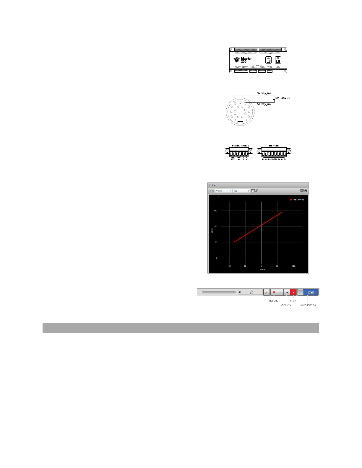
Principle of 3D Acquisition
The Gocator 2300 series sensors are line
profiler sensors, meaning that they capture a
single 3D profile for each camera exposure. The
sensor projects a laser line onto the target. The
sensor's camera views the laser from an angle,
and captures the reflection of the light off the
target. Because of this triangulation angle, the
laser line appears in different positions on the
camera depending on the 3D shape of the
target. Gocator sensors are always precalibrated to deliver 3D data in engineering
units throughout the specified measurement
range.
Target objects are typically moved under the sensor on a transportation mechanism, such as a conveyor
belt. The sensor captures a series of 3D slices, building up the full scan of the object. Sensor speed and
required exposure time to measure the target are typically critical factors in applications with line profiler
sensors.
Gocator 2300 & 2880 Series
38
Resolution and Accuracy
Delete this text and replace it with your own content.
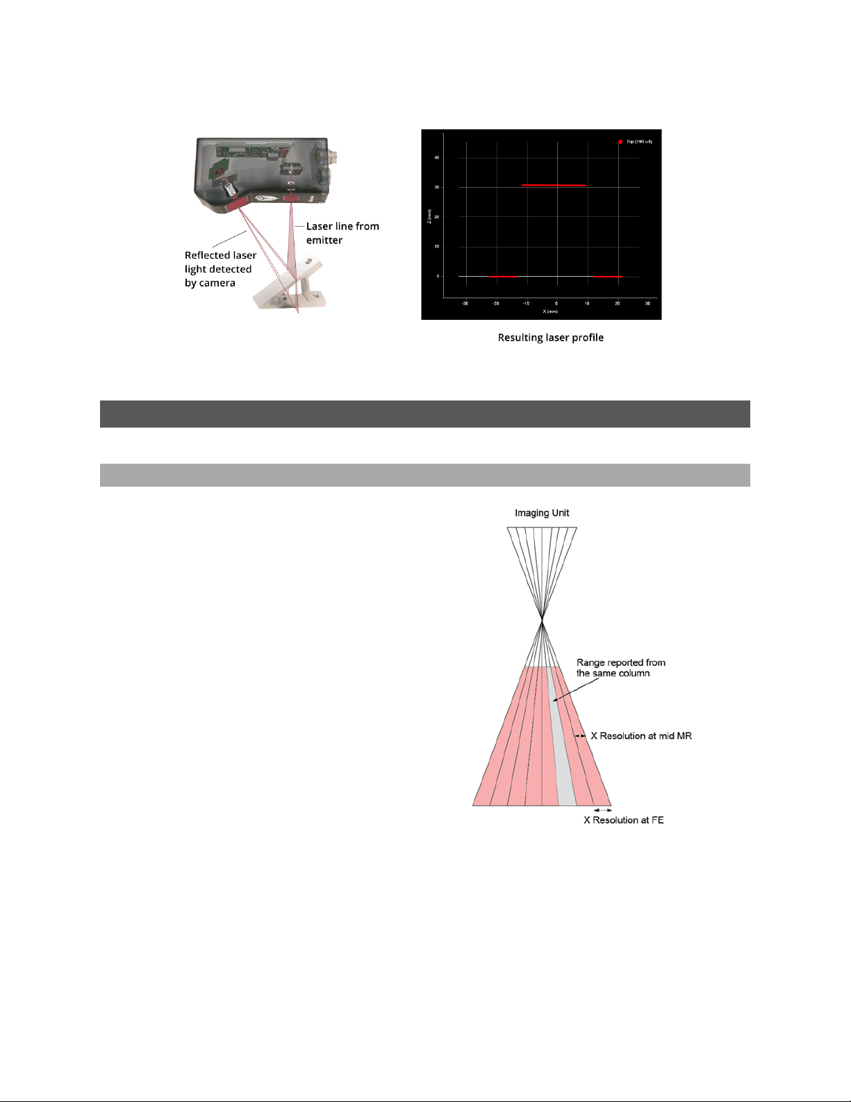
X Resolution
X resolution is the horizontal distance between
each measurement point along the laser line.
This specification is essentially based on the
number of camera columns used to cover the
field of view (FOV) at a particular measurement
range .
Since the FOV is trapezoidal, the distance
between points is closer at the near range than
at the far range. This is reflected in the Gocator
data sheet as the two numbers quoted for X
resolution.
X resolution is important for how accuratel the
width of a target can be measured.
NOTE: When the Gocator runs in Profile mode
and Uniform Spacing is enabled, the 3D data
is resampled to an X interval that is different
from the raw camera resolution.
Gocator 2300 & 2880 Series
Theory of Operation • 3D Acquisition • 39

Z Resolution
Z resolution is the variability of the height
measurement, in each individual 3D point, with
the target at a fixed position. This variability is
caused by camera imager and sensor
electronics.
Like X resolution, the Z resolution is better at
the close range and worse at the far range. This
is reflected in the Gocator data sheet as the two
numbers quoted for Z resolution.
Z Resolution gives an indication of the smallest
detectable height difference.
Z Linearity
Z Linearity is the difference between the actual
distance to the target and the measured
distance to the target, throughout the
measurement range.
Z Linearity is expressed in the Gocator data
sheet as a percentage of the total
measurement range.
Z Linearity gives an indication of the sensor's
ability to measure absolute distance
Gocator 2300 & 2880 Series
Theory of Operation • 3D Acquisition • 40

Profile Output
Gocator measures the height of the object calculated from laser triangulation. The Gocator reports a
series of ranges along the laser line, with each range representing the distance from the sensor's origin
plane. Each range contains a height and a position in the sensor's field of view.
Coordinate Systems
Range data is reported in sensor or system coordinates depending on the alignment state. The
coordinate systems are described below.
Sensor Coordinates
Before alignment, individual sensors use the
coordinate system shown here.
The Z axis represents the sensor's measurement
range (MR), with the values increasing towards the
sensor.
The X axis represents the sensor's field of view
(FOV).
The origin is at the center of the MR and FOV.
In Surfacedata, the Y axis represents the relative
position of the part in the direction of travel.
Y position increases as the object moves forward
(increasing encoder position).
System Coordinates
Alignment is used with a single sensor to
compensate for mounting misalignment and to
set a zero reference, such as a conveyor belt
surface. Alignment is also used to set a
common coordinate system for dual-sensor
systems. In both cases, alignment determines
the adjustments to X, Z, and tilt (rotation in the
X–Z plane) needed to align the data from each
sensor. The adjustments resulting from
alignment are called transformations. See
Alignment (page 85) for more information on
alignment.
System coordinates are aligned so that the
system X axis is parallel to the alignment target
surface. The system Z origin is set to the base of
the alignment target object. The tilt angle is
positive when rotating from the X to the Z axis.
Similar to the sensor coordinates, Y positions
increase when the encoder increases.
Gocator 2300 & 2880 Series
Theory of Operation • Profile Output • 41

For Wide and Opposite layouts, profiles and
measurements from the Main and Buddy
sensors are expressed in a unified coordinate
system. Isolated layouts express results using a
separate coordinate system for each sensor.
Resampled and Uniform Spacing Profile Format
Profile data produced in Profile mode is available in two formats: with and without uniform spacing.
Uniform spacing is enabled in the Scan Mode panel, on the Scan page.
With uniform spacing enabled, the ranges that make up a profile are resampled so that the spacing is
uniform along the laser line (X axis). The resampling divides the X axis into fixed size "bins." Profile points
that fall into the same bin are combined into a single range value (Z). The size of the spacing interval can
be set under the Spacing tab in the Sensor panel on Scan page.
As a result, in the Ethernet data channel, only the range values (Z) are reported and the X positions can
be reconstructed through the array index at the receiving end (the client).
Resampling to uniform spacing reduces the complexity for downstream algorithms to process the profile
data from the Gocator, but places a higher processing load on the sensor's CPU.
In contrast, the profile format without uniform spacing set requires no processing on the sensor. Ranges
arereported in (X, Z) coordinate pairs. This frees up processing resources in the Gocator, but usually
requires more complicated processing on the client side.
All built-in measurement tools in the Gocator operate on profiles with uniform spacing in both Profile
and Surface mode.
Gocator 2300 & 2880 Series
Theory of Operation • Profile Output • 42

Gocator Web Interface
The following sections describe the Gocator web interface.
User Interface Overview
Gocator sensors are configured by connecting to a Main sensor with a web browser. The Gocator web
interface is illustrated below.
Element Description
1 Manage page Contains settings for sensor system layout, network, motion and alignment,
handling jobs, and sensor maintenance. See System Management and
Maintenance (page 51).
2 Scan page Contains settings for scan mode, trigger source, detailed sensor configuration,
and performing alignment. See Scan Setup and Alignment (page 65).
3 Measure page
Gocator 2300 & 2880 Series
Contains built-in measurement tools and their settings. See Measurement
(page 111).
43

Element Description
4 Output page Contains settings for configuring output protocols used to communicate
measurements to external devices. See Output (page 187).
5 Dashboard page
Provides monitoring of measurement statistics and sensor health. See
Dashboard (page 198).
6 CPULoad and Speed
7 Help Provides links to the user manual and SDK.
8 Toolbar Controls sensor operation, manages jobs, and replays recorded measurement
9 Configuration area Provides controls to configure scan and measurement tool settings.
10 Data viewer
11 Log
Provides important sensor performance metrics. See Metrics Area (page 50).
data. See Toolbar (below).
Displays sensor data, tool setup controls, and measurements. See Data Viewer
on page 99 for its use when the Scan page is active and on page 112 for its use
when the Measure page is active.
Displays messages from the sensor (errors, warnings, and other information).
See Log (page 49).
Common Elements
Toolbar
The toolbar is used for performing common operations. This section explains how to use the toolbar to
manage jobs and to operate the sensor.
Element Description
1 Job controls For saving and loading different jobs.
2 Recorded data controls For downloading, uploading, and exporting recorded data.
3 Sensor operation / replay control Use the sensor operation controls to start sensors, enable
recording, and control recorded data.
4 Replay switch Toggles the sensor data source between live and replay.
Saving and Loading Settings
When you change sensor settings using the Gocator web interface, some changes are saved
automatically, whileother changes are temporary until you save them manually. The following table lists
the types of information that can be saved in a sensor.
Setting Type Behavior
Network Address
Gocator 2300 & 2880 Series
Network address changes are saved when you click the Save button in Networking on
Gocator Web Inter face • User Interface Overview • 44

Setting Type Behavior
the Manage page. The sensor must be reset before changes take effect.
Job Most of the settings that can be changed in the Gocator's web interface, such as the ones
in the Manage, Measure, and Output pages, are temporary until saved in a job file.
Each sensor can have multiple job files. If there is a job file that is designated as the
default, it will be loaded automatically when the sensor is reset.
Alignment
Alignment can either be fixed or dynamic, as controlled by the Alignment Reference
setting in Motion and Alignment in the Manage page.
Alignment is saved automatically at the end of the alignment procedure when
Alignment Reference is set to Fixed. When Alignment Reference is set to
Dynamic, however, you must manually save the job to save alignment.
The job drop-down list shows the list of jobs stored in the sensor. The job that is currently active is listed
at the top. The job name will be marked with "[unsaved]" to indicate any unsaved changes.
To save a job:
1. Select a job in the job drop-down list.
l
If you are creating a new job, choose [New] in the job drop-down list and enter a name for the job.
l
If you are saving changes to an existing job, choose the job in the job drop-down list.
2. Press the Enter key or click the Save button .
The job will be saved to sensor storage using the name you provided. Saving a job automatically sets it
as the default, that is, the job loaded when then sensor is restarted.
To activate an existing job:
1. Select an existing file name in the job drop-down list.
The job will be activated from sensor storage. If there are any unsaved changes to the current job, you
will be asked whether you want to discard those changes.
Detailed management of jobs is handled in the Jobs panel in the Manage page. See Jobs (page 58) for
more information.
Managing Multiple Settings
A Gocator can store several hundred jobs. Being ableto switch between different jobs is useful when a
Gocator is used with different constraints during separate production runs (for example, width decision
constraints might be loose during one production run and tight during another depending on the
desired grade of the part).
Gocator 2300 & 2880 Series
Gocator Web Inter face • User Interface Overview • 45

Switching active jobs can be done manually through the web interface as described under To activate an
existing job in Saving and Loading Settings on page 44. Switching active jobs can also be done
programmatically using the supported industrial protocols (Modbus, EtherNet/IP, and ASCII), the
Gocator’s native Ethernet protocol, and through the SDK.
Recording, Playback, and Measurement Simulation
Gocator sensors can record and replay data, and can also simulate measurement tools on recorded data.
This feature is most often used for troubleshooting and fine-tuning measurements, but can also be
helpful during setup.
Recording and playback are controlled by using the toolbar controls.
Recording and playback controls when replay is off
To record live data:
1. Toggle Replay mode off by setting the slider to the left in the Toolbar.
2. Press the Record button to enable recording.
When replay is off and recording is enabled, the sensor will store the most recent data as it runs.
Remember to disable recording if you no longer wish to record live data (press the Record button again
to disable recording).
3. Press the Snapshot button or Start button.
The Snapshot records a single frame. The Start button will run the sensor continuously and all frames
will be recorded, up to available memory. When the memory limit is reached, the oldest data will be
discarded.
Newly recorded data is appended to existing replay data unless the sensor job has been
modified.
Gocator 2300 & 2880 Series
Gocator Web Inter face • User Interface Overview • 46

Recording and playback controls when replay is on
To replay recorded data:
1. Toggle Replay mode on by setting the slider to the right in the Toolbar.
The slider's background will turn blue and a Replay Mode Enabled message will be displayed.
2. Use the Replay slider or the Step Forward, Step Back, or Play buttons to review data.
The Step Forward and Step Back buttons move and the current replay location backward and forward
by a single frame, respectively.
The Play button advances the replay location continuously, animating the playback.
The Stop button (replaces the Play button while playing) can be used to pause the replay at a particular
location.
The Replay slider (or Replay Position box) can be used to go to a specific replay frame.
To simulate measurements on recorded data:
1. Toggle Replay mode on by setting the slider to the right in the Toolbar.
The slider's background will turn blue and a Replay Mode Enabled message will be displayed.
2. Go to the Measure page.
Modify settings for existing measurements, add new measurement tools, or delete measurement tools
as desired.
3. Use the Replay Slider, Step Forward, Step Back, or Play button to simulate measurements.
Step or play through recorded data to execute the measurement tools on the recording.
Individual measurement values can be viewed directly in the data viewer. Statistics on the
measurements that have been simulated can be viewed in the Dashboard page; see Dashboard (page
198).
To clear recorded data:
1. Stop the sensor if it is running by clicking on the Stop button.
2. Click on the Clear Replay Data button .
Gocator 2300 & 2880 Series
Gocator Web Inter face • User Interface Overview • 47

Downloading, Exporting, and Uploading Recorded Data
Recorded data can be downloaded or exported to the client computer or uploaded to the Gocator.
Export is often used for processing the recorded data using third-party tools. Recorded data can also be
downloaded in a binary format, which is used to back up the data for reviewing in the future.
Recorded data is not saved or loaded when you save or activate jobs in the toolbar.
To download recorded data:
1. Toggle Replay mode on by setting the slider to the right in the Toolbar.
The slider's background will turn blue and a Replay Mode Enabled message will be displayed.
2. Click the Download button .
To upload recorded data:
1. Toggle Replay mode on by setting the slider to the left in the Toolbar.
The slider's background will turn blue and a Replay Mode Enabled message will be displayed.
2. Click the Upload button .
3. Select the directory and the file name to upload from the client computer and click on OK.
Recorded data can be exported using the CSVformat. If Acquire Intensity has been enabled in the
Scan Mode panel on the Scan page, intensity data will be included in the exported CSVfile.
To export recorded data to CSV:
1. Toggle Replay mode on by setting the slider to the right in the Toolbar.
The slider's background will turn blue and a Replay Mode Enabled message will be displayed.
2. Click the Export button and select Export Range Data as CSV.
Gocator 2300 & 2880 Series
Gocator Web Inter face • User Interface Overview • 48

In Profile mode, all data in the record buffer is exported. In Surface mode, only data at the current
replay location is exported.
Use the playback control buttons to move to a different replay location; see To replay recorded data in
Recording, Playback, and Measurement Simulation on page 46 for more information on playback.
3. Optionally, convert exported data to another format using the CSV Converter Tool on page 326.
Recorded intensity data can be exported to a bitmap (.BMP format). Acquire Intensity must be
checked in the Scan Mode panel while data was being recorded in order to export intensity data.
To export recorded intensity data to BMP:
1. Toggle Replay mode on by setting the slider to the right in the Toolbar.
The slider's background will turn blue and a Replay Mode Enabled message will be displayed.
2. Click the Export button and select Intensity data as BMP.
Only the intensity data in the current replay location is exported.
Use the playback control buttons to move to a different replay location; see To replay recorded data in
Recording, Playback, and Measurement Simulation on page 46 for more information on playback.
Log
The log, located at the bottom of the web interface, is a centralized location for all messages that the
Gocator displays, including warnings and errors.
To use the log:
1. Click on the Log open button at the bottom of the web interface.
2. Click on the appropriate tab for the information you need.
Gocator 2300 & 2880 Series
Gocator Web Inter face • User Interface Overview • 49

Metrics Area
The Metrics area displays two important sensor performance metrics: CPU load and speed (current
frame rate).
The CPU bar in the Metrics panel (at the top of the interface) displays how much of the CPU is being
utilized. A warning symbol ( ) will appear next to the CPUbar if the sensor drops profiles because the
CPU is over-loaded.
CPUat 100%
CPUwarning message
The Speed bar displays the frame rate of the sensor. A warning symbol ( ) will appear next to it if
triggers (external input or encoder) are dropped because the external rate exceeds the maximum frame
rate.
In both cases, a warning message will be temporarily displayed in the lower right corner of the web
interface. Click on the warning symbol ( ) to redisplay the warning message.
Open the log for details on the warning. See Log (previous page) for more information.
Data Viewer
The data viewer is displayed in both the Scan and the Measure pages, but displays different
information depending on which page is active.
When the Scan page is active, the data viewer displays sensor data and can be used to adjust regions of
interest. Depending on the selected operation mode (page 66), the data viewer can display video images,
3Dprofiles, or 3D surfaces. For details, see Data Viewer (page 99).
When the Measure page is active, the data viewer displays sensor data onto which representations of
measurement tools and their measurements are superimposed. For details, see Data Viewer (page 112).
Because Gocator 2880 has two cameras, two profiles are displayed in the Gocator web
interface.
Gocator 2300 & 2880 Series
Gocator Web Inter face • User Interface Overview • 50

System Management and Maintenance
The following sections describe how to set up the sensor connections and networking, how to calibrate
encoders and choose alignment reference, and how to perform maintenance tasks.
Manage Page Overview
Gocator's system and maintenance tasks are performed on the Manage page.
Element Description
1 Sensor System
2 Networking
3 Motion and Alignment
4 Jobs
5 Security
6 Maintenance
Gocator 2300 & 2880 Series
Contains settings for configuring sensor system and layout, and boot-up. See
Sensor System (next page).
Contains settings for configuring the network. See Networking (page 55).
Contains settings to configure the encoder. See Motion and Alignment (page
56).
Lets you manage jobs stored on the sensor. See Jobs (page 58).
Lets you change passwords. See Security (page 60).
Lets you upgrade firmware, create/restore backups, and reset sensors. See
Maintenance (page 61).
Gocator Web Inter face • System Management and Maintenance • 51

Sensor System
The following sections describe the Sensor System category on the Manage page. This category lets
you choose the layout standalone or dual-sensor systems, and provides other system settings.
Dual-sensor layouts are only displayed when a Buddy sensor has been assigned.
Sensor Autostart
With the Autostart setting enabled, laser ranging profiling and measurement functions will begin
automatically when the sensor is powered on. Autostart must be enabled if the sensor will be used
without being connected to a computer.
To enable/disable Autostart:
1. Go to the Manage page and click on the Sensor System category.
2. Check/uncheck the Autostart option in the Main section.
Dual-Sensor System Layout
Mounting orientations must be specified for a dual-sensor system. This information allows the
alignment procedure to determine the correct system-wide coordinates for laser profiling and
Gocator 2300 & 2880 Series
Gocator Web Inter face • System Management and Maintenance • 52

measurements. See Coordinate Systems (page 41) for more information on sensor and system
coordinates.
Supported Layouts
Orientation Example
Standalone
The sensor operates as an isolated device.
Wide
Sensors are mounted in Left (Main) and Right
(Buddy) positions for a larger combined field
of view. Sensors may be angled to avoid
occlusions.
Reverse
Sensors are mounted in a left-right layout as
with the Wide layout, but the Buddy sensor
is mounted such that it is rotated 180
degrees around the Z axis to prevent
occlusion along the Y axis.
Opposite
Sensors are mounted in Top (Main) and
Bottom (Buddy) positions for a larger
combined measurement range and the
ability to perform Top/Bottom differential
measurements.
Gocator 2300 & 2880 Series
Gocator Web Inter face • System Management and Maintenance • 53

To specify the layout:
1. Go to the Manage page and click on the Sensor System category.
2. Select an assigned Buddy sensor in the Visible Sensors list.
See Buddy Assignment (below) for information on assigning a Buddy Sensor.
3. Select a layout by clicking on one of the Layout buttons.
See the table above for information on layouts.
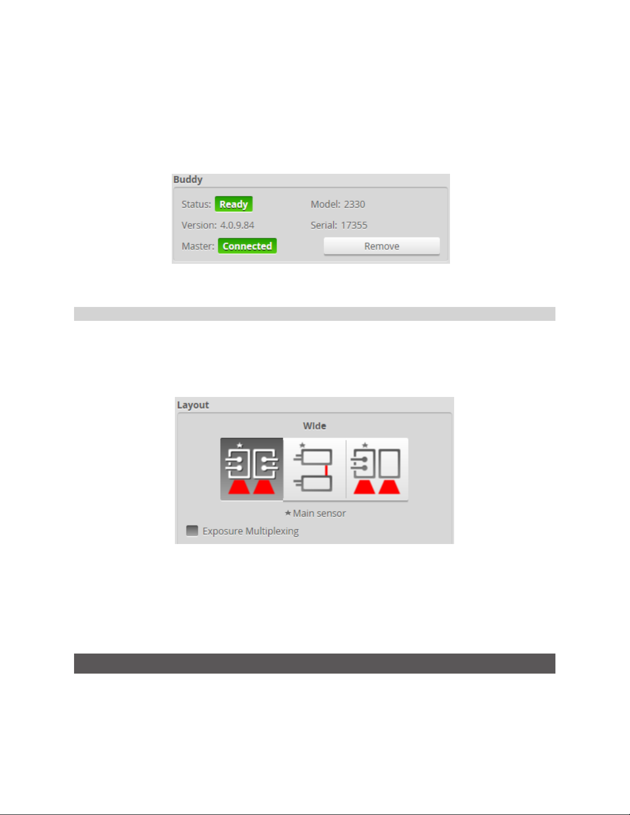
Buddy Assignment
In a dual-sensor system, the Main sensor assumes control of the Buddy sensor after the Buddy sensor is
assigned to the Main sensor. Configuration for both sensors can be performed through the Main
sensor's interface.
Main and Buddy sensors must be assigned unique IP addresses before they can be used on the
same network. Before proceeding, connect the Main and Buddy sensors one at a time (to avoid
an address conflict) and use the steps outline in Running a Dual-Sensor System (page 30) to
assign each sensor a unique address.
When a sensor is acting as a Buddy, it is not discoverable and its web interface is not
accessible.
To assign a Buddy sensor:
1. Go to the Manage page and click on the Sensor System category.
Gocator 2300 & 2880 Series
Gocator Web Inter face • System Management and Maintenance • 54
2. Select a sensor in the Visible Sensors list.
3. Click the Assign button.
A sensor can only be assigned as a Buddy if its firmware and model number match the firmware and
model number of the Main sensor. The Assign button will be greyed out if a sensor cannot be assigned
as a Buddy.
The Buddy sensor will be assigned to the Main sensor and its status will be updated in the System panel.
To remove a Buddy, click on the Remove button.
Exposure Multiplexing
If the Main and Buddy sensors are mounted such that the camera from one sensor can detect the laser
from the other sensor, the Exposure Multiplexing option can be used to eliminate laser interference.
This setting creates a time offset for laser exposures and ensures that interfering lasers are not strobed
at the same time. Using the Exposure Multiplexing option may reduce the maximum frame rate.
To enable/disable exposure multiplexing:
1. Go to the Manage page and click on the Sensor System category.
2. In the Layout section, check/uncheck the Exposure Multiplexing option.
This option is only displayed if a buddy is assigned.
Networking
The Networking category on the Manage page provides network settings. Settings must be configured
to match the network to which the Gocator sensors are connected.
Gocator 2300 & 2880 Series
Gocator Web Inter face • System Management and Maintenance • 55

To configure the network settings:
1. Go to the Manage page.
2. In the Networking category, specify the Type, IP, Subnet Mask, and Gateway settings.
The Gocator sensor can be configured to use DHCP or assigned a static IP address.
3. Click on the Save button.
You will be prompted to confirm your selection.
Motion and Alignment
The Motion and Alignment category on the Manage page lets you configure alignment reference,
encoder resolution, and travel speed.
Gocator 2300 & 2880 Series
Gocator Web Inter face • System Management and Maintenance • 56

Alignment Reference
The Alignment Reference setting can have one of two values: Fixed or Dynamic.
Setting Description
Fixed A single global alignment is used for all jobs. This is typically used when the sensor
mounting is constant over time and between scans, for example, when the sensor is
mounted in a permanent position over a conveyor belt.
Dynamic A separate alignment is used for each job. This is typically used when the sensor’s
position relative to the object scanned is always changing, for example, when the
sensor is mounted on a robot arm moving to different scanning locations.
To configure alignment reference:
1. Go to the Manage page and click on the Motion and Alignment category.
2. In the Alignment section, choose Fixed or Dynamic in the Alignment Reference drop-down.
Encoder Resolution
You can manually enter the encoder resolution in the Resolution setting , or it can be automatically set
by performing an alignment with Type set to Moving. Establishing the correct encoder resolution is
Gocator 2300 & 2880 Series
Gocator Web Inter face • System Management and Maintenance • 57

required for correct scaling of the scan of the target object in the direction of travel.
Encoder resolution is expressed in millimeters per tick.
To configure encoder resolution:
1. Go to the Manage page and click on the Motion and Alignment category.
2. In the Encoder section, enter a value in the Resolution field.
Encoder Value and Frequency
The encoder value and frequency are used to confirm the encoder is correctly wired to the Gocator and
to manually calibrate encoder resolution (that is, by moving the conveyor system a known distance and
making a note of the encoder value at the start and end of movement).
Travel Speed
The Travel Speed setting is used to correctly scale scans in the direction of travel in systems that lack an
encoder but have a conveyor system that is controlled to move at constant speed. Establishing the
correct travel speed is required for correct scaling of the scan in the direction of travel.
Travel speed is expressed in millimeters per second.
To manually configure travel speed:
1. Go to the Manage page and click on the Motion and Alignment category.
2. In the Speed section, enter a value in the Travel Speed field.
Travel speed can also be set automatically by performing an alignment with Type set to Moving (see
page87).
Jobs
The Jobs category on the Manage page lets you manage the jobs stored on the sensor.
Gocator 2300 & 2880 Series
Gocator Web Inter face • System Management and Maintenance • 58

Element Description
Namefield Used to provide a job name when saving files.
Jobs list Displays the jobs that are currently saved in the sensor's flash storage.
Save button Saves current settings to the job using the name in the
Load button Loads the job that is selected in the file list. Reloading the current job discards any unsaved
changes.
Delete button Deletes the job that is selected in the jobs list.
Set as Default
button
Download...
button
Upload... button Uploads a job from the client computer.
Sets the selected job as the default to be loaded at boot time. When the default job is selected, this
button is used to clear the default.
Downloads the selected jobs to the client computer.
Job Name
field.
Jobs can be loaded and set as default independently. For example, Job1 could be loaded, while Job2 is
set as the default. Default jobs load automatically when a sensor is power cycled or reset.
Unsaved jobs are indicated by "[unsaved]".
Gocator 2300 & 2880 Series
Gocator Web Inter face • System Management and Maintenance • 59

To download, load, or delete a job, or to set one as a default or clear a default:
1. Go to the Manage page and click on the Jobs category.
2. Select a job in the Jobs list.
3. Click on the appropriate button for the operation.
To save a job:
1. Go to the Manage page and click on the Jobs category.
2. Provide a name in the Job Name field.
To save an existing job under a different name, click on it in the Jobs list and then modify it in the Job
Name field.
3. Click on the Save button or press Enter.
Saving a job automatically sets it as the default, that is, the job loaded when then sensor is restarted.
Security
Gocator sensors can be secured with passwords to prevent unauthorized access. Each sensor has two
accounts: Administrator and Technician.
Gocator Account Types
Gocator 2300 & 2880 Series
Gocator Web Inter face • System Management and Maintenance • 60

Account Description
Administrator The Administrator account has privileges to use the toolbar (loading and saving jobs, recording and
viewing replay data), to view all pages and edit all settings, and to perform setup procedures such as
sensor alignment.
Technician The Technician account has privileges to use the toolbar (loading and saving jobs, recording and
viewing replay data), to view the
Dashboard
page, and to start or stop the sensor.
The Administrator and Technician accounts can be assigned unique passwords. By default, passwords
areblank (empty).
To set or change the password for the Administrator account:
1. Go to the Manage page and click on the Security category.
2. In the Administrator section, enter the Administrator account password and password confirmation.
3. Click Change Password.
The new password will be required the next time that an administrator logs in to the sensor.
To set or change the password for the Technician account:
1. Go to the Manage page and click on the Security category.
2. In the Technician section, enter the Technician account password and password confirmation.
3. Click Change Password.
The new password will be required the next time that a technician logs in to the sensor.
If the administrator or technician password is misplaced, the sensor can be recovered using a special
software tool. See Sensor Recovery Tool (page 319) for more information.
Maintenance
The Maintenance category in the Manage page is used to do the following:
l
upgrade the firmware and check for firmware updates;
l
back up and restore all saved jobs and recorded data;
l
restore the sensor to factory defaults;
l
reset the sensor.
Gocator 2300 & 2880 Series
Gocator Web Inter face • System Management and Maintenance • 61

Sensor Backups and Factory Reset
You can create sensor backups, restore from a backup, and restoreto factory defaults in the
Maintenance category.
Backup files contain all of the information stored on a sensor, including jobs and alignment.
An Administrator should create a backup file in the unlikely event that a sensor fails and a
replacement sensor is needed. If this happens, the new sensor can be restored with the backup
file.
To create a backup:
1. Go to the Manage page and click on the Maintenance category.
2. Click the Backup... button under Backup and Restore.
3. When you are prompted, save the backup.
Backups are saved as a single archive that contains all of the files from the sensor.
Gocator 2300 & 2880 Series
Gocator Web Inter face • System Management and Maintenance • 62

To restore from a backup:
1. Go to the Manage page and click on the Maintenance category.
2. Click the Restore... button under Backup and Restore.
3. When you are prompted, select a backup file to restore.
The backup file is uploaded and then used to restore the sensor. Any files that were on the sensor
before the restore operation will be lost.
To restore a sensor to its factory default settings:
1. Go to the Manage page and click on Maintenance.
2. Consider making a backup.
Before proceeding, you should perform a backup. Restoring to factory defaults cannot be undone.
3. Click the Factory Restore... button under Factory Restore.
You will be prompted whether you want to proceed.
Firmware Upgrade
LMI recommends routinely updating firmware to ensure that Gocator sensors always have the latest
features and fixes.
In order for the Main and Buddy sensors to work together, they must be use the same firmware
version. This can be achieved by upgrading through the Main sensor or by upgrading each
sensor individually.
To download the latest firmware:
1. Go to the Manage page and click on the Maintenance category.
2. Click the Check Updates... button in the Firmware section.
Gocator 2300 & 2880 Series
Gocator Web Inter face • System Management and Maintenance • 63

3. Download the latest firmware.
If a new version of the firmware is available, follow the instructions to download it to the client
computer.
If the client computer is not connected to the Internet, firmware can be downloaded and transferred to
the client computer by using another computer to download the firmware from LMI's website:
http://www.lmi3D.com/support/downloads.
To upgrade the firmware:
1. Go to the Manage page and click on the Maintenance category.
2. Click the Upgrade... button in the Firmware section.
3. Provide the location of the firmware file in the File dialog.
4. Wait for the upgrade to complete.
After the firmware upgrade is complete, the sensor will self-reset. If a buddy has been assigned, it will
be upgraded and reset automatically.
Gocator 2300 & 2880 Series
Gocator Web Inter face • System Management and Maintenance • 64

Scan Setup and Alignment
The following sections describe the steps to configure Gocator sensors for laser profiling using the Scan
page. Setup and alignment should be performed before adding and configuring measurements or
outputs.
Scan Page Overview
The Scan page lets you configuresensors and perform alignment.
Element Description
1 Scan Mode panel Contains settings for the current scan mode (Video, Profile, or Surface) and other options.
See Scan Modes (next page).
2 Trigger panel
3 Sensor panel
4 Alignment panel
5 Filters panel
6 Part Detection
panel
7 Surface Generation
Gocator 2300 & 2880 Series
Contains trigger source and trigger-related settings. See Triggers (page 67).
Contains settings for an individual sensor, such as active area or exposure. See Sensor (page
72).
Used to perform alignment. See Alignment (page 85).
Contains settings for post-processing of the profiles. See Filters (page 90).
Used to set the part detection logic for sorting profiles into discrete objects. See Part
Detection (page 95).
Contains settings for surface generation. See Surface Generation (page 93).
Gocator Web Inter face • Scan Setup and Alignment • 65

Element Description
panel
8 Data Viewer Displays sensor data and adjust regions of interest. Depending on the current operation
mode, the data viewer can display video images , profile plots, or surface views . See Data
Viewer (page 99).
The following table provides quick references for specific goals that you can achieve from the panels in
the Scan page.
Goal Reference
Select a trigger source that is appropriate for the application.
Ensure that camera exposure is appropriate for laser profiling .
Find the right balance between profile quality, speed, and CPU utilization.
Triggers (next page)
Exposure (page 76)
Active Area (page 73)
Exposure (page 76)
Gocator Device Files (page 201)
Specify mounting orientations for dual-sensor systems.
Dual-Sensor System Layout
(page 52)
Calibrate the system so that laser profile data can be aligned to a common
reference and values can be correctly scaled in the axis of motion.
Set up the part detection logic to create discrete objects from surfaces or profiles.
Specify smoothing, gap-filling, and resampling parameters to remove effects of
occlusions.
Aligning Sensors (page 87)
Part Detection (page 95)
Filters (page 90)
Scan Modes
The Gocator web interface supports threescan modes: Video, Profile, and Surface. The scan mode can
be selected in the Scan Mode panel.
Mode and Option Description
Video Outputs video images from the Gocator. This mode is useful for configuring exposure
Gocator 2300 & 2880 Series
Gocator Web Inter face • Scan Setup and Alignment • 66

Mode and Option Description
time and troubleshooting stray light or ambient light problems.
Profile Outputs profiles and performs profile measurements. Video images are processed
internally to produce laser profiles and cross-sectional measurements.
Surface
Outputs 3D point clouds made up of many laser profiles combined together and
performs surface measurements. The sensor uses various methods to generate a
surface (see page 93). Part detection can be enabled on a surface to identify discrete
parts (see page 95).
Uniform Spacing
When this option is enabled, ranges are resampled to a uniform spacing along the X
axis (see page 42 for more information). The size of the spacing can be set in the
Spacing tab (see page 82).
When the option is disabled, the Gocator outputs unprocessed range data. Ranges are
reported in (x,z) coordinate pairs. Disable this option to extract ranges from the
Gocator at the highest possible rate. Post-profiling processing and measurements are
disabled.
This option is not available when in Surface mode.
Acquire Intensity When this option is enabled, an intensity value will be produced for each
point
.
laser profile
Triggers
A trigger is an event that causes a sensor to take a single picture. Triggers are configured in the Trigger
panel on the Scan page.
When a trigger is processed, the laser is strobed and the camera exposes to produce an image. The
resulting image is processed inside the sensor to yield a profile (range/distance information), which can
then be used for measurement.
The laser and camera inside a sensor can be triggered by one of the following sources:
Trigger Source Description
Time
Sensors have an internal clock that can be used to generate fixed-frequency triggers.
The external input can be used to enable or disable the time triggers.
Encoder
An encoder can be connected to provide triggers in response to motion. Three encoder
triggering behaviors are supported. These behaviors are set using the Behavior
setting.
Ignore Backward
A scan is triggered when the target object moves forward. If the target object moves
backward, it must move forward by at least the distance that the target travelled
backward, plus one encoder spacing, to trigger the next scan.
Gocator 2300 & 2880 Series
Gocator Web Inter face • Scan Setup and Alignment • 67

Trigger Source Description
Track Backward
A scan is triggered only when the target object moves forward. If the target object
moves backward, it must move forward by at least the distance of one encoder spacing
to trigger the next scan.
Bi-directional
A scan is triggered when the target object moves forward or backward.
Gocator 2300 & 2880 Series
Gocator Web Inter face • Scan Setup and Alignment • 68

Trigger Source Description
When triggers are received at a frequency higher than the maximum frame rate, some
triggers may not be accepted. The Trigger Drops Indicator in the Dashboard can be
used to check for this condition.
The external input can be used to enable or disable the encoder triggers.
See Encoder Input (page 356) for more information on connecting the encoder to
Gocator sensors.
External Input
A digital input can provide triggers in response to external events (e.g., photocell).
When triggers are received at a frequency higher than the maximum frame rate, some
triggers may not be accepted. The Trigger Drops Indicator in the Dashboard page
can be used to check for this condition.
See Digital Inputs (page 355) for more information on connecting external input to
Gocator sensors.
Software
A network command can be used to send a software trigger. See Protocols (page 248)
for more information.
For examples of typical real-world scenarios, see next page. For information on the settings used with
each trigger source, see page 71
Gocator 2300 & 2880 Series
Gocator Web Inter face • Scan Setup and Alignment • 69

Trigger Examples
Example: Encoder + Conveyor
Encoder triggering is used to perform profile
measurements at a uniform spacing.
The speed of the conveyor can vary while the
object is being measured; an encoder ensures
that the measurement spacing is consistent,
independent of conveyor speed.
Example: Time + Conveyor
Time triggering can be used instead of encoder
triggering to perform profile measurements at
a fixed frequency.
Measurement spacing will be non-uniform if
the speed of the conveyor varies while the
object is being measured.
It is strongly recommended to use an encoder
with transport-based systems due to the
difficulty in maintaining constant transport
velocity.
Example: External Input + Conveyor
External input triggering can be used to
produce a snapshot for profile measurement.
For example, a photocell can be connected as
an external input to generate a trigger pulse
when a target object has moved into position.
An external input can also be used to gate the
trigger signals when time or encoder triggering
is used. For example, a photocell could
generate a series of trigger pulses as long as
there is a target in position.
Gocator 2300 & 2880 Series
Gocator Web Inter face • Scan Setup and Alignment • 70

Example: Software Trigger + Robot Arm
Software triggering can be used to produce a
snapshot for profile measurement.
A software trigger can be used in systems that
use external software to control the activities
of system components.
Trigger Settings
The trigger source is selected using the Trigger panel in the Scan page.
After specifying a trigger source, the Trigger panel shows the parameters that can be configured.
Parameter Trigger Source Description
Source All Selects the trigger source (
Software
Frame Rate Time Controls the frame rate. Select
down to lock to the maximum frame rate. Fractional values are
supported. For example, 0.1 can be entered to run at 1 frame
every 10 seconds.
Gate on External Input Time, Encoder
Gocator 2300 & 2880 Series
External input can be used to enable or disable profiling in a
sensor. When this option is enabled, the sensor will respond to
).
Gocator Web Inter face • Scan Setup and Alignment • 71
Time, Encoder,External Input
Max Speed
from the drop-
, or

Parameter Trigger Source Description
time or encoder triggers only when the external input is
asserted.
This setting is not displayed when Surface Generation is set
to Fixed Length, Variable Length, or Rotational (see page
93).
See See Digital Inputs (page 355) for more information on
connecting external input to Gocator sensors.
Behavior Encoder
Spacing Encoder Specifies the distance between triggers (mm). Internally the
Units External Input, Software Specifies whether the trigger delay, output delay, and output
Trigger Delay External Input
Specifies how the Gocator sensor is triggered when the target
moves. Can be Track Backward, Ignore Backward, or BiDirectional. See Triggers (page 67) for more information on
these behaviors.
Gocator sensor rounds the spacing to a multiple of the encoder
resolution.
scheduled command operate in the time
domain. The unit is implicitly set to microseconds with Time
trigger source
Controls the amount of time or the distance the sensor waits
before producing a frame after the external input is activated.
This is used to compensate for the positional difference
between the source of the external input trigger (e.g.,
photocells) and the sensor.
Trigger delay is only supported in single exposure mode; for
details, see Exposure (page 76).
, and millimeters with Encoder trigger source
or the encoder
Depending on the surface generation settings, some trigger options may not be available.
.
To configure the trigger source:
1. Go to the Scan page.
2. Expand the Trigger panel by clicking on the panel header.
3. Select the trigger source from the drop-down.
4. Configure the settings.
See the trigger parameters above for more information.
5. Save the job in the Toolbar by clicking the Save button .
Sensor
The following sections describe the settings that are configured in the Sensor panel on the Scan page.
Gocator 2300 & 2880 Series
Gocator Web Inter face • Scan Setup and Alignment • 72

Active Area
Active area refers to the region within the sensor's maximum field of view that is used for laser profiling.
By default, the active area covers the sensor's entirefield of view. By reducing the active area, the sensor
can operate at higher speeds.
Active area is specified in sensor coordinates, rather
than in system coordinates. As a result, if the sensor
is already alignment calibrated, press the Acquire
button to display uncalibrated data before
configuring the active area. See Coordinate Systems
(page 41) for more information on sensor and
system coordinates.
To set the active area:
1. Go to the Scan page.
2. Choose Profile or Surface mode in the Scan Mode panel.
If one of these modes is not selected, you will not be able to configure the active area.
3. Expand the Sensor panel by clicking on the panel header or the button.
4. Click the button corresponding to the sensor you want to configure.
Gocator 2300 & 2880 Series
Gocator Web Inter face • Scan Setup and Alignment • 73

The button is labeled Top, Bottom, Top-Left, or Top-Right, depending on the system.
Active area is specified separately for each sensor.
5. Click on the Active Area tab.
6. Click the Select button.
7. Click the Acquire button to see a scan while setting the active area.
8. Set the active area.
Enter the active area values in the edit boxes or adjust the active area graphically in the data viewer.
9. Click the Save button in the Sensor panel.
Click the Cancel button to cancel setting the active area.
10. Save the job in the Toolbar by clicking the Save button .
Laser profiling devices are usually more accurate at the near end of their measurement range.
If your application requires a measurement range that is small compared to the maximum
measurement range of the sensor, mount the sensor so that the active area can be defined at
the near end of the measurement range.
Tracking Window
The Gocator can track a relatively flat object in real-time to achieve very high scan rates. This feature
tracks the object height using a small window that moves dynamically to cover a larger measurement
range. You can balance the gain in speed and the tracking ability by configuring the size of the tracking
area. This feature is typically used in road or web scanning applications where the target is a continuous
flat surface.
A laser line remains tracked as long as the percentage of detected laser points exceeds the user-defined
search threshold. When the sensor loses track of the laser line, the sensor will search for the laser line
using the full active area.
Gocator 2300 & 2880 Series
Gocator Web Inter face • Scan Setup and Alignment • 74

To enable the tracking window:
1. Go to the Scan page.
2. Choose Profile or Surface mode in the Scan Mode panel.
If one of these modes is not selected, you will not be able to set the tracking window.
3. Expand the Sensor panel by clicking on the panel header.
4. Click on the Active Area tab.
5. Check the Tracking Window box.
The panel below the checkbox expands and shows the settings for the window used to track the object
height.
6. Click the tracking window's Select button.
7. Resize the tracking window shown in the data viewer.
Only the height of the window is required. You can move the position of the tracking window to cover a
live profile to help adjust the window height.
8. Edit the Search Threshold setting.
The search threshold defines the minimum percentage of the points detected across the profile for the
laser to be considered tracked. If tracking is lost, the sensor will search for the laser using the full active
area.
9. Click the Save button in the Sensor panel.
10. Save the job in the Toolbar by clicking the Save button .
The sensor adjusts the position of the tracking window so that the area is centered around the average
height of the entire visiblelaser profile. You should adjust the lighting and the active area to remove all
background objects, such as the conveyor belt surface, ambient lights, etc.
Gocator 2300 & 2880 Series
Gocator Web Inter face • Scan Setup and Alignment • 75

Transformations
The transformation settings are used to control how profiles are converted from sensor coordinates to
system coordinates.
Parameter Description
X Offset Specifies the shift along the X axis. With Normal orientation, a positive value shifts the
the right. With Reverse orientation, a positive value shifts the
Z Offset Specifies the shift along the Z axis. A positive value shifts the
Angle Specifies the tilt (rotation in the X-Z plane). A positive value rotates the profile counter-clockwise.
profiles
profiles
to the left.
toward the sensor.
profiles
to
When applying the transformations, Angle is applied before the X and Z offsets.
To configure transformation settings:
1. Go to the Scan page.
2. Choose Profile or Surface mode in the Scan Mode panel.
If one of these modes is not selected, you will not be able to configure the transformations.
3. Expand the Sensor panel by clicking on the panel header.
4. Click the button corresponding to the sensor you want to configure.
The button is labeled Top, Bottom, Top-Left, or Top-Right, depending on the system.
Transformations can be configured separately for each sensor.
5. Expand the Transformations area by clicking on the expand button .
See the table above for more information.
6. Set the parameter values.
See the table above for more information.
7. Save the job in the Toolbar by clicking the Save button .
8. Check that the transformation settings are applied correctly after profiling is restarted.
Exposure
Exposure determines the duration of camera and laser on-time. Longer exposures can be helpful to
detect laser signals on dark or distant surfaces, but increasing exposure time decreases the maximum
speed. Different target surfaces may require different exposures for optimal results. Gocator sensors
provide three exposure modes for the flexibility needed to scan different types of target surfaces.
Gocator 2300 & 2880 Series
Gocator Web Inter face • Scan Setup and Alignment • 76

Exposure Mode Description
Single Uses a single exposure for all objects. Used when the surface is uniform and is the same for
all targets.
Dynamic Automatically adjusts the exposure after each frame. Used when the target surface varies
between scans.
Multiple Uses multiple exposures to create a single profile. Used when the target surface has a varying
reflectance within a single profile (e.g., white and black).
Video mode lets you see how the laser line appears on the camera and identify any stray light or
ambient light problems. When exposure is tuned correctly, the laser should be clearly visible along the
entire length of the viewer. If it is too dim, increase the exposure value; if it is too bright decrease
exposure value.
Under exposure
Laser line is not detected.
Increase the exposure value.
Over exposure
Laser line is too bright .
Increase the exposure value.
When the Gocator is in Multiple exposure mode, select which exposure to view using the drop-down box
next to "View" in the data viewer. This drop-down is only visible in Video scan mode when the Multiple
option is selected in the Exposure section in the Sensor panel.
Single Exposure
The sensor uses a fixed exposure in every scan. Single exposure is used when the target surface is
uniform and is the same for all parts.
Gocator 2300 & 2880 Series
Gocator Web Inter face • Scan Setup and Alignment • 77

To enable single exposure:
1. Place a representative target in view of the sensor.
The target surface should be similar to the material that will normally be measured.
2. Go to the Scan page.
3. Expand the Sensor panel by clicking on the panel header.
4. Click the button corresponding to the sensor you want to configure.
The button is labeled Top, Bottom, Top-Left, or Top-Right, depending on the system.
Exposure can be configured separately for each sensor.
5. Click on the Exposure tab.
6. Select Single from the Exposure Mode drop-down.
7. Edit the Exposure setting.
You can automatically tune the exposure by pressing the Auto Set button, which causes the sensor to
turn on and tune the exposure time.
8. Run the sensor and check that laser profiling is satisfactory.
If laser profiling is not satisfactory, adjust the exposure values manually. Switch to Video mode to use
video to help tune the exposure; see Exposure (page 76) for details.
Dynamic Exposure
The sensor automatically uses past profile information to adjust the exposure to yield the best profile.
This is used when the target surface changes from scan to scan.
Gocator 2300 & 2880 Series
Gocator Web Inter face • Scan Setup and Alignment • 78

To enable dynamic exposure:
1. Go to the Scan page.
2. Expand the Sensor panel by clicking on the panel header or the button.
3. Click the button corresponding to the sensor you want to configure.
The button is labeled Top, Bottom, Top-Left, or Top-Right, depending on the system.
Exposure can be configured separately for each sensor.
4. Click on the Exposure tab.
5. Select Dynamic from the Exposure Mode drop-down.
6. Set the minimum and maximum exposure.
The auto-set function can be used to automatically set the exposure. First, place the brightest target in
the field of view and press the Auto Set Min button to set the minimum exposure. Then, place the
darkest target in the field of view and press the Auto Set Max button to set the maximum exposure.
7. Run the sensor and check that laser profiling is satisfactory.
If laser profiling is not satisfactory, adjust the exposure values manually. Switch to Video mode to use
video to help tune the exposure; see Exposure (page 76) for details.
Multiple Exposure
The sensor combines data from multiple exposures to create a single laser profile . Multiple exposures
can be used to increasethe ability to detect light and dark materials that are in the field of view
simultaneously.
Gocator 2300 & 2880 Series
Gocator Web Inter face • Scan Setup and Alignment • 79

Up to five exposures can be defined with each set to a different exposure level. For each exposure, the
sensor will perform a complete scan at the current frame rate making the effective frame rate slower.
For example, if two exposures are selected, then the speed will be half of the single exposure frame rate.
The sensor will perform a complete multi-exposure scan for each external input or encoder trigger.
The resulting profile is a composite created by combing data collected with different exposures. The
sensor will choose profile data that is available from the lowest-numbered exposure step. It is
recommended to use a larger exposure for higher-numbered steps.
To enable multiple exposure:
1. Go to the Scan page.
2. Expand the Sensor panel by clicking on the panel header or the button.
3. Click the button corresponding to the sensor you want to configure.
The button is labeled Top, Bottom, Top-Left, or Top-Right, depending on the system.
Exposure can be configured separately for each sensor.
4. Click on the Exposure tab.
5. Select Multiple from the Exposure Mode drop-down.
6. Click the button to add an exposure step.
Up to a maximum of five exposure settings can be added.
To remove an exposure, select it in the exposure list and click the button.
7. Set the exposure level for each exposure to make the Gocator's camera less or more sensitive, as
required.
Gocator 2300 & 2880 Series
Gocator Web Inter face • Scan Setup and Alignment • 80

If Acquire Intensity is enabled, select the exposure step that is used to capture the intensity output.
8. If Acquire Intensity is enabled, select the exposure step that is used to capture the intensity output.
9. Run the sensor and check that laser profiling is satisfactory.
If laser profiling is not satisfactory, adjust the exposure values manually. Switch to Video mode to use
video to help tune the exposure; see Exposure (page 76) for details.
Spacing
The Spacing tab lets you configure settings related to spacing (sub-sampling and spacing interval).
Gocator 2300 & 2880 Series
Gocator Web Inter face • Scan Setup and Alignment • 81

Sub-Sampling
Sub-sampling reduces the number of camera columns or rows that are used for laser profiling, reducing
the resolution. Reducing the resolution increases speed or reduces CPU usage while maintaining the
sensor's field of view. Sub-sampling can be set independently for the X axis and Z axis.
The X sub-sampling setting is used to decrease the profile's X resolution to decrease sensor CPU usage.
The X setting works by reducing the number of imagecolumns used for laser profiling.
The Z sub-sampling setting is used to decrease the profile's Z resolution to increasespeed. The Z setting
works by reducing the number of image rows used for laser profiling.
Sub-sampling values are expressed as fractions in the Web interface. For example, an X sub-sampling
value of 1/2 indicates that every second camera column will be used for laser profiling.
The CPU Load bar at the top of the interface displays how much the CPU is being used.
Both the X and the Z sub-sampling settings must be decreased to increase speed.
To configure X or Z sub-sampling:
1. Go to the Scan page.
2. Expand the Sensor panel by clicking on the panel header or the button.
3. Click the button corresponding to the sensor you want to configure.
The button is labeled Top, Bottom, Top-Left, or Top-Right, depending on the system.
X and Z sub-sampling can be configured separately for each sensor.
4. Click on the Spacing tab.
5. Select an X or Z sub-sampling value.
6. Save the job in the Toolbar by clicking the Save button .
7. Check that laser profiling is satisfactory.
Spacing Interval
Spacing interval is the spacing between data points in resampled data. (Resampled data is only produced
if the Uniform Spacing option in the Scan Mode panel is checked.) A larger interval creates profiles
with lower X resolution, reduces CPU usage, and potentially increases the maximum frame rate. A larger
interval also reduces the data output rate. For moreinformation on resampled data, see Resampled and
Uniform Spacing Profile Format (page 42).
The Uniform Spacing option must be checked in the Scan Mode panel for the Spacing
Interval option to be displayed.
Gocator 2300 & 2880 Series
Gocator Web Inter face • Scan Setup and Alignment • 82

To configure the spacing interval:
1. Go to the Scan page.
2. Choose Profile or Surface mode in the Scan Mode panel.
If one of these modes is not selected, you will not be able to configure the spacing interval.
3. Expand the Sensor panel by clicking on the panel header or the button.
4. Click the button corresponding to the sensor you want to configure.
The button is labeled Top, Bottom, Top-Left, or Top-Right, depending on the system.
Spacing is specified separately for each sensor.
5. Click on the Spacing tab.
6. Select a spacing interval level.
Speed: Uses the lowest X resolution within the active area as the spacing interval. This setting
minimizes CPU usage and data output rate, but the profile has the lowest X resolution (i.e., least detail).
Balanced: Uses the X resolution at the middle of the active area as the spacing interval. This setting
balances CPU load, data output rate, and X resolution.
Resolution: Uses the highest X resolution within the active area as the spacing interval. This setting
maximizes resolution but has higher CPU load and has the highest data output rate (i.e., greatest
detail).
7. Save the job in the Toolbar by clicking the Save button .
Material
Profile data acquisition can be configured to suit different types of target materials. This helps maximize
the number of useful profile points produced. For many targets, the setting it is not necessary, but it can
Gocator 2300 & 2880 Series
Gocator Web Inter face • Scan Setup and Alignment • 83

make a great difference with others.
Preset material types can be selected in the Materials setting.
When Materials is set to Custom, the following settings can be configured:
Setting Description
Spot Threshold
Spot Width Max
Spot Selection
Gocator 2300 & 2880 Series
The minimum increase in intensity level between neighbouring pixels for a pixel to be
considered the start of a potential spot.
This setting is important for filtering false profile spots generated by sunlight reflection.
The maximum number of pixels a spot is allowed to span.
This setting can be used to filter out data caused by background light if the unwanted
light is wider than the laser and does not merge into the laser itself. A lower Spot
Width setting reduces the chance of false detection, but limits the ability to detect
features/surfaces that elongate the spot.
Determines the spot selection method (Best, Top, or Bottom).
Best selects the strongest spot in a given column on the imager. Top (the topmost spot
or the one farthest to the left on the imager) and Bottom (the bottommost spot or the
one farthest to the right on the imager) can be useful in applications where there are
reflections, flying sparks or smoke, which are always on one side of the laser.
Gocator Web Inter face • Scan Setup and Alignment • 84

Setting Description
Analog
Digital
Sensitivity
Threshold The minimum number of spots for dynamic exposure to consider the spot valid. If the
Analog
dynamic range is not a critical factor.
Digital
dynamic range is not a critical factor.
Controls the exposure that dynamic exposure converges to. The lower the value, the
lower the exposure Gocator will settle on.
The trade-off is between the number of exposure spots and the possibility of over-
exposing.
number of spots is below this threshold, the algorithm will walk over the allowed
exposure range slowly to find the correct exposure.
camera gain can be used when the application is severely exposure limited, yet
camera gain can be used when the application is severely exposure limited, yet
To configure material:
1. Go to the Scan page.
2. Expand the Sensor panel by clicking on the panel header or the button.
3. Click the button corresponding to the sensor you want to configure.
The button is labeled Top, Bottom, Top-Left, or Top-Right, depending on the system.
Materials can be configured separately for each sensor.
4. Click on the Materials tab.
5. Choose a material in the Materials drop-down or choose Custom to manually configure settings.
See the table above for the customizable settings.
6. Save the job in the Toolbar by clicking the Save button .
7. Check that laser profiling is satisfactory.
After adjusting the setting, confirm that laser profiling is satisfactory.
Various settings can affect how the Material settings behave. You can use Video mode to examine how
the settings interact. See Spots and Dropouts (page 102) for more information.
Alignment
Gocator sensors are pre-calibrated and ready to deliver profiles in engineering units (mm) out of the box.
However, alignment procedures are required to compensate for sensor mounting inaccuracies, to align
multiple sensors into a common coordinate system, and to determine the resolution (with encoder) and
speed of the transport system. Alignment is performed using the Alignment panel on the Scan page.
Once alignment has been completed, the derived transformation values will be displayed under
Transformations in the Sensor panel; see Transformations (page 76) for details.
Alignment States
A Gocator can be in one of three alignment states: None, Manual, or Auto.
Gocator 2300 & 2880 Series
Gocator Web Inter face • Scan Setup and Alignment • 85

Alignment State
State Explanation
None Sensor is not aligned.
Manual Transformations (
manually edited.
Auto
Sensor is aligned using the alignment procedure (see next page).
Profiles
see page 76
are reported in default sensor coordinates.
or encoder resolution (see page 71)
)
have been
An indicator on the Alignment panel will display ALIGNED or UNALIGNED, depending on the Gocator's
state.
Alignment Types
Gocator sensors support two types of alignment, which are related to whether the target is stationary or
moving.
Type Description
Stationary
Moving
Stationary is used when the sensor mounting is constant over time and between
scans, e.g., when the sensor is mounted in a permanent position over a conveyor
belt.
Moving is used when the sensor's position relative to the object scanned is
always changing, e.g., when the sensor is mounted on a robot arm moving to
different scanning locations.
Alignment: With and Without Encoder Calibration
For systems that use an encoder, encoder calibration can be performed while aligning sensors. The table
below summarizes the differences between performing alignment with and without encoder calibration
calibration.
With encoder calibration Without encoder calibration
Target Type Calibration
Target/Sensor Motion Linear motion Stationary
Calibrates Tilt Yes Yes
Calibrates Z axis Offset Yes Yes
Calibrates X axis Offset Yes Yes (Calibration bar required)
Calibrates Encoder Yes No
Calibrates Travel Speed Yes No
disk or calibration
bar Flat surface or calibration bar
See Coordinate Systems (page 41) for definitions of coordinate axes. See Calibration Targets (page 23) for
descriptions of calibration disks and bars.
See Aligning Sensors (next page) for the procedure to perform alignment. After alignment, the coordinate
system for laser profiles will change from sensor coordinates to system coordinates.
Gocator 2300 & 2880 Series
Gocator Web Inter face • Scan Setup and Alignment • 86

Aligning Sensors
Alignment can be used to compensate for mounting inaccuracies by aligning sensor data to a common
reference surface (often a conveyor belt).
To prepare for alignment:
1. Choose an alignment reference in the Manage page if you have not already done so.
See Alignment Reference (page 57) for more information.
2. Go to the Scan page.
3. Choose Profile or Surface mode in the Scan Mode panel.
If one of these modes is not selected, the Alignment panel will not be displayed.
4. Expand the Alignment panel by clicking on the panel header or the button.
5. Ensure that all sensors have a clear view of the target surface.
Remove any irregular objects from the sensor's field of view that might interfere with alignment. If
using a bar for a dual-sensor system, ensure that the lasers illuminate a reference hole on the bar.
To perform alignment for stationary targets:
1. In the Alignment panel, select Stationary as the Type.
2. Clear the previous alignment if present.
Press the Clear Alignment button to remove an existing alignment.
3. Select an alignment Target.
l
Select Flat Surface to use the conveyor surface (or other flat surface) as the alignment
reference
l
Select Bar to use a custom calibration bar. If using a calibration bar, specify the bar
dimensions and reference hole layout. See Calibration Targets (page 23) for details.
Configure the characteristics of the target.
Gocator 2300 & 2880 Series
Gocator Web Inter face • Scan Setup and Alignment • 87

4. Place the target under the sensor
5. Click the Align button.
The sensors will start, and the alignment process will take place. Alignment is performed
simultaneously for all sensors. If the sensors do not align, check and adjust the exposure settings (page
76).
Alignment uses the exposure defined for single exposure mode, regardless of the
current exposure mode
6. Use Profile mode to inspect alignment results.
Laser profiles from all sensors should now be aligned to the alignment target surface. The base of the
alignment target (or target surface) provides the origin for the system Z axis.
To perform alignment for moving targets:
1. Do one of the following if you have not already done so.
l
If the system uses an encoder, configure encoder resolution. See Encoder Resolution (page
57) for more information.
l
If the system does not use an encoder, configure travel speed. See Travel Speed (page58)
for more information.
2. In the Alignment panel, select Moving as the Type.
3. Clear the previous alignment if present.
Press the Clear Alignment button to remove an existing alignment.
4. Select an alignment Target.
l
Select one of the disk Disk options to use a disk as the alignment reference.
l
Select Bar to use a custom calibration bar. If using a calibration bar, specify the bar
dimensions and reference hole layout. See Calibration Targets (page 23) for details.
Configure the characteristics of the target.
Gocator 2300 & 2880 Series
Gocator Web Inter face • Scan Setup and Alignment • 88

5. Place the target under the sensor
6. If the system uses an encoder and you want to calibrate it, check the Encoder Calibration checkbox.
7. Click the Align button.
The sensors will start and then wait for the calibration target to pass through the laser plane.
Alignment is performed simultaneously for all sensors. If the sensors do not align, check and adjust the
exposure settings (page 76).
Alignment uses the exposure defined for single exposure mode, regardless of the
current exposure mode
8. Engage the transport system.
When the calibration target has passed completely through the laser plane, the calibration process will
complete automatically. To properly calibrate the travel speed, the transport system must be running
at the production operating speed before the target passes through the laser plane.
9. Use Profile mode to inspect alignment results.
Laser profiles from all sensors should now be aligned to the alignment target surface. The base of the
alignment target (or target surface) provides the origin for the system Z axis.
When using an alignment bar, there can be at most one hole in each sensor's field of view.
Clearing Alignment
Alignment can be cleared to revert the sensor to sensor coordinates.
Gocator 2300 & 2880 Series
Gocator Web Inter face • Scan Setup and Alignment • 89

To clear alignment:
1. Go to the Scan page.
2. Choose Profile or Surface mode in the Scan Mode panel.
If one of these modes is not selected, the Alignment panel will not be displayed.
3. Expand the Alignment panel by clicking on the panel header or the button.
4. Click the Clear Alignment button.
The alignment will be erased and sensors will revert to using sensor coordinates.
Filters
Filters are used to post-process data along the X or Yaxis to remove noise or clean it up before it is
output or is used by measurement tools. The following types of filters are supported:
Filter Description
Gap Filling Fills in missing data caused by occlusions using information from the nearest neighbors.
Gap filling also fills gaps where no data is detected, which can be due to the surface
reflectivity, for example dark or specular surface areas, or to actual gaps in the surface.
Median Substitutes the value of a data point with the median within a specified window around
the data point.
Smoothing Applies moving window averaging to reduce random noise.
Decimation Reduces the number of data points.
Filters are applied in the order displayed in the table above. The filters are configured in the Filters panel
on the Scan page.
Gap Filling
Gap filling works by filling in missing data points using either the lowest values from the nearest
neighbors or linear interpolation between neighboring values (depending on the Z difference between
neighboring values), in a specified window. The sensor can fill gaps along both the X axis and the Y axis. X
gap filling works by filling in the gaps within the same profile. Y gap filling works by filling in gaps in the
direction of travel at each X location.
If both X and Y gap filling are enabled, missing data is filled along the X and Yaxes at the same time, using
the available neighboring data.
Gocator 2300 & 2880 Series
Gocator Web Inter face • Scan Setup and Alignment • 90

In Profile mode, Gap Filling is limited to the Xaxis. (The Y setting is not available.)
To configure X or Ygap filling:
1. Go to the Scan page.
2. Choose Profile or Surface mode in the Scan Mode panel.
If one of these modes is not selected, you will not be able to configure gap filling.
3. Expand the Filters panel by clicking on the panel header or the button.
4. Click on the Gap Filling tab.
5. Enable the X or Y setting and select the maximum width value.
The value represents the maximum gap width that the Gocator will fill. Gaps wider than the maximum
width will not be filled.
6. Save the job in the Toolbar by clicking the Save button .
7. Check that the laser profiling is satisfactory.
Median
The Median filter substitutes the value of a data point with the median calculated within a specified
window around the data point.
Missing data points will not be filled with the median value calculated from data points in the
neighbourhood.
Gocator 2300 & 2880 Series
Gocator Web Inter face • Scan Setup and Alignment • 91
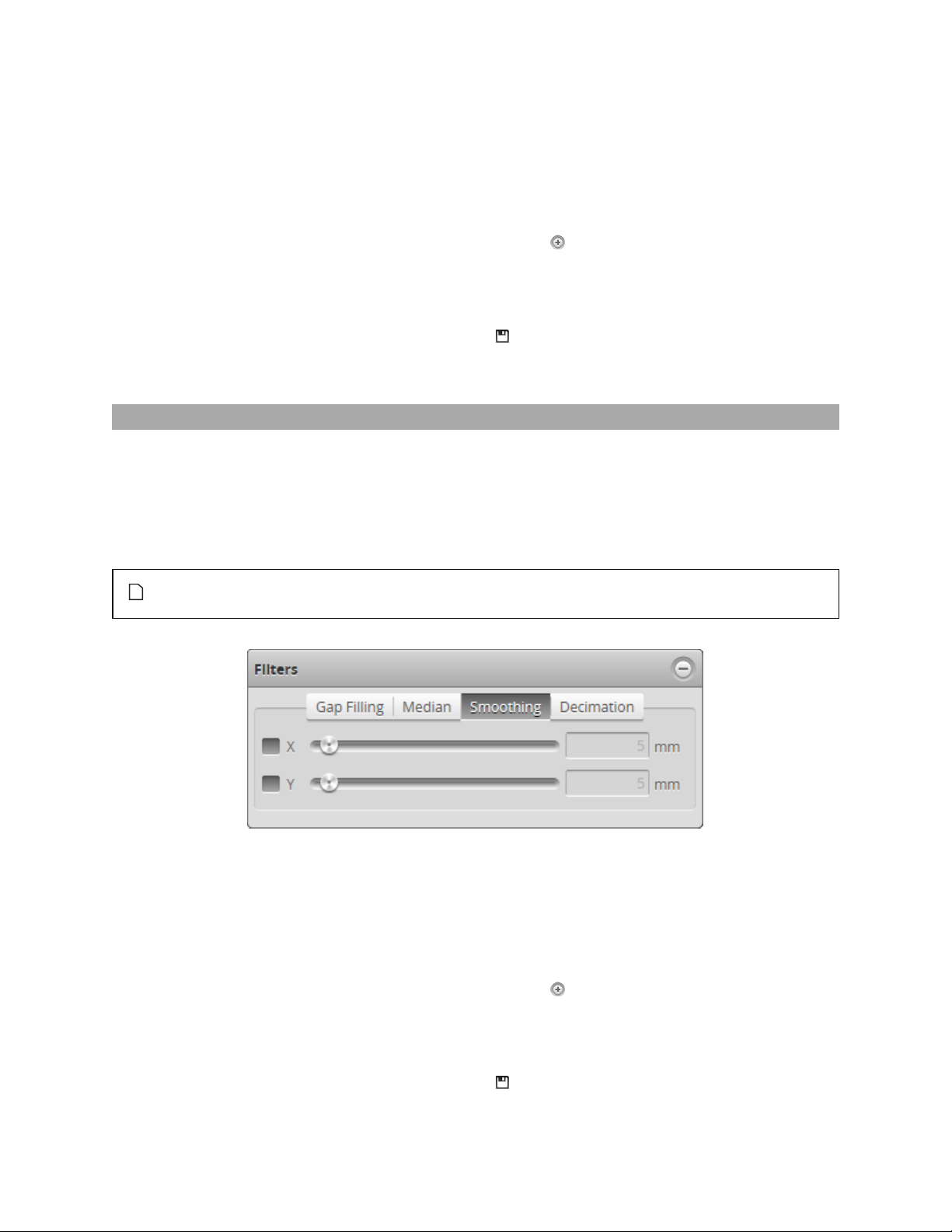
To configure X or Ymedian:
1. Go to the Scan page.
2. Choose Profile or Surface mode in the Scan Mode panel.
If one of these modes is not selected, you will not be able to configure gap filling.
3. Expand the Filters panel by clicking on the panel header or the button.
4. Click on the Median tab.
5. Enable the X or Y setting and select the maximum width value.
6. Save the job in the Toolbar by clicking the Save button .
7. Check that the laser profiling is satisfactory.
Smoothing
Smoothing works by substituting a data point value with the average value of that data point and its
nearest neighbors within a specified window.Smoothing can be applied along the X axis or the Y axis. X
smoothing works by calculating a moving average across samples within the same profile. Y smoothing
works by calculating a moving average in the direction of travel at each X location.
If both X and Y smoothing are enabled, the data is smoothed along X axis first, then along the Y axis.
Missing data points will not be filled with the mean value calculated from data points in the
neighbourhood.
To configure X or Ysmoothing:
1. Go to the Scan page.
2. Choose Profile or Surface mode in the Scan Mode panel.
If one of these modes is not selected, you will not be able to configure smoothing.
3. Expand the Filters panel by clicking on the panel header or the button.
4. Click on the Smoothing tab.
5. Enable the X or Ysetting and select the averaging window value.
6. Save the job in the Toolbar by clicking the Save button .
Gocator 2300 & 2880 Series
Gocator Web Inter face • Scan Setup and Alignment • 92

7. Check that the laser profiling is satisfactory.
Decimation
Decimation reduces the number of data points along the Xor Yaxis by choosing data points at the end
of a specified window around the data point. For example, by setting X to .2, points will be used every .2
millimeters.
To configure X or Ydecimation:
1. Go to the Scan page.
2. Choose Profile or Surface mode in the Scan Mode panel.
If one of these modes is not selected, you will not be able to configure smoothing.
3. Expand the Filters panel by clicking on the panel header or the button.
4. Click on the Decimation tab.
5. Enable the X or Ysetting and select the decimationwindow value.
6. Save the job in the Toolbar by clicking the Save button .
7. Check that the laser profiling is satisfactory.
Surface Generation
The sensor can generate a surface using different methods, depending on the needs of the application.
Surface generation is configured in the Surface Generation panel on the Scan page.
Gocator 2300 & 2880 Series
Gocator Web Inter face • Scan Setup and Alignment • 93

The following types correspond to the Type setting in the panel.
Continuous: Part detection is always automatically
enabled, and the sensor continuously generates surfaces
of parts that are detected under the sensor. See Part
Detection (next page) for descriptions of the settings that
control detection logic.
Fixed Length: The sensor generates surfaces of a fixed
length (in mm) using the value in the Length setting.
For correct length measurement, you should ensure that
motion is calibrated (that is, encoder resolution for
encoder triggers or travel speed time triggers).
The Type setting provides two types of start triggers:
o
Sequential: Continuously generates back to back fixed
length surfaces.
o
External Input: A pulse on the digital input triggers
the generation of a single surface of fixed length.
For more information on connecting external input to a
Gocator sensor, see page 355.
You can optionally enable part detection to process the
surface after it has been generated, but the generation
itself does not depend on the detection logic.
Variable Length: The sensor generates surfaces of
variable length. Profiles collected while the external digital
input is held high are combined to form a surface. If the
value of the Max Length setting is reached while external
input is still high, the next surface starts directly with the
next profile. For correct length measurement, you should
ensure that motion is calibrated (i.e., encoder resolution
for encoder triggers or travel speed for time triggers).
For more information on connecting external input to a
Gocator 2300 & 2880 Series
Gocator Web Inter face • Scan Setup and Alignment • 94

Gocator sensor, see page 355.
You can optionally enable part detection to process the
surface after it has been generated, but the generation
itself does not depend on the detection logic.
Rotational: The sensor reorders profiles within a surface
to be aligned with the encoder’s index pulse. That is,
regardless of the radial position the sensor is started at,
the generated surface always starts at the position of the
index pulse. If the index pulse is not detected and the
rotation circumference is met, the surface is dropped and
the Encoder Index Drop indicator will be incremented.
To scan exactly one revolution of a circular
target without knowing the circumference,
manually set the encoder resolution (page57)
to 1, the encoder trigger spacing (page 67) to
(number of encoder ticks per revolution) /
(number of desired profiles per revolution),
and Encoder Resolution in the Surface
Generation panel to the number of encoder
ticks per revolution.
You can optionally enable part detection to process the
surface after it has been generated, but the generation
itself does not depend on the detection logic.
To configure surface generation:
1. Go to the Scan page and choose Surface in the Scan Mode panel.
If this mode is not selected, you will not be able to configure surface generation.
2. Expand the Surface Generation panel by clicking on the panel header or the button.
3. Choose an option from the Type drop-down and any additional settings.
See the types and their settings described above.
Part Detection
In Surface mode, the Gocator sensor can analyze the 3Dpoint cloud created from profiles to identify
discrete objects. Surface measurements can then be performed on each discrete object. Part detection is
configured using the Part Detection panel on the Scan page.
Part detection must be manually enabled when Type is set to Fixed Length, Variable Length, or
Rotational in the Surface Generation panel. When Type is set to Continuous, part detection is
automatically enabled.
Part detection can be performed when Source in the Trigger panel is set to Time or Encoder. To use
the Time trigger source, the travel speed must be calibrated. To use the Encoder trigger source, the
encoder resolution must be calibrated. See Aligning Sensors (page 87) for more information.
Gocator 2300 & 2880 Series
Gocator Web Inter face • Scan Setup and Alignment • 95

Multiple parts can pass through the laser at the same time and will be individually tracked. Parts can be
separated along the laser line (X axis), in the direction of travel (Y axis), or by gated external input.
The following settings can be tuned to improve the accuracy and reliability of part detection.
Setting Description
Height Threshold
Determines the profile height threshold for part detection. The setting for Threshold
Direction determines if parts should be detected above or below the threshold. Above is
typically used to prevent the belt surface from being detected as a part when scanning
objects on a conveyor.
In an Opposite layout, the threshold is applied to the difference between the top and the
bottom profile.A target thinner than the threshold value is ignored, including places
where only one of either top or bottom is detected.
To separate parts by gated external input, set the Height Threshold to the active area Z
offset (i.e., minimum Z position of the current active area), set Source to Time or
Encoder and check the Gate Using External Input checkbox in the Trigger panel
(page 67).
Threshold Direction Determines if parts should be detected above or below the height threshold.
Gocator 2300 & 2880 Series
Gocator Web Inter face • Scan Setup and Alignment • 96

Setting Description
Gap Width Determines the minimum separation between objects on the X axis. If parts are closer
than the gap interval, they will be merged into a single part.
Gap Length
Padding Width Determines the amount of extra data on the X axis from the surface surrounding the
Padding Length Determines the amount of extra data on the Y axis from the surface surrounding the
Min Area Determines the minimum area for a detected part. Set this value to a reasonable
Max Part Length Determines the maximum length of the part object. When the object exceeds the
Frame of Reference Determines the coordinate reference for dsurface measurements.
Determines the minimum separation between objects on the Y axis. If parts are closer
than the gap interval, they will be merged into a single part.
detectedpart that will be included. This is mostly useful when processing part data with
third-party software such as HexSight, Halcon, etc.
detectedpart that will be included. This is mostly useful when processing part data with
third-party software such as HexSight, Halcon, etc.
minimum in order to filter out small objects or noise.
maximum length, it is automatically separated into two parts. This is useful to break a
long object into multiple sections and perform measurements on each section.
Sensor
When Frame of Reference is set to Sensor, the sensor's frame of reference is used.
The way the sensor's frame of reference is defined changes depending on the Type
surface generation setting (see page 93 for more information):
l
When parts are segmented from a continuous surface (the surface generation Type
setting is set to Continuous), measurement values are relative to a Yorigin sensor
frame of reference at the center of the part (the same as for Part frame of reference;
see below).
l
When parts are segmented from other types of surfaces (the surface generation Type
setting is set to Fixed Length, Variable Length, or Rotational), measurement
values are relative to a Yorigin sensor frame of reference at the center of the surface
from which the part is segmented.
The Bounding Box GlobalXand GlobalYmeasurements are exceptions:regardless of the
Frame of Reference setting,
Part
When Frame of Reference is set to Part, all measurements except Bounding Box X and
Y are relative to the center of the bounding box of the part. For Bounding Box X and Y,
the measurement values are always relative to the Sensor frame of reference.
Edge Filtering
See Edge Filtering (next page).
To set up part detection:
1. Go to the Scan page and choose Surface in the Scan Mode panel.
If this mode is not selected, you will not be able to configure part detection.
2. Expand the Part Detection panel by clicking on the panel header or the button.
3. Adjust the settings.
See the part detection parameters above for more information.
Gocator 2300 & 2880 Series
Gocator Web Inter face • Scan Setup and Alignment • 97

Edge Filtering
Part scans sometimes contain noise around the edges of the target. This noise is usually caused by the
sensor’s light being reflected off almost vertical sides, rounded corners, etc. Edge filtering helps reduce
edge noise in order to produce more accurate and repeatable volume and area measurements, as well as
to improve positioning of relative measurement regions. Optionally, the Preserve Interior Feature
setting can be used to limit filtering to the outside edges of the target.
Edge Filtering disabled (scan shows reflection noise)
Gocator 2300 & 2880 Series
Edge Filtering enabled (reflection noise eliminated or reduced)
Gocator Web Inter face • Scan Setup and Alignment • 98

Edge Filtering enabled, Preserve Interior Feature enabled.
To configure edge filtering:
1. Go to the Scan page and choose Surface in the Scan Mode panel.
If this mode is not selected, you will not be able to configure part detection.
2. Expand the Part Detection panel by clicking on the panel header or the button and enable part
detection if necessary.
Part detection can be enabled and disabled when Type in the Surface Generation panel is set to Fixed
Length, Variable Length, or Rotational. Part detection is automatically enabled when Type is set to
Continuous.
3. Check the Edge Filtering checkbox to enable edge filtering.
4. Configure the Width and Length settings.
The Width and Length settings represent the size of the filter on the X axis and the Y axis, respectively.
5. Set the Preserve Interior Feature setting if necessary.
The Preserve Interior Feature setting limits filtering to the outside edges of the target.
Data Viewer
The data viewer can display video images, profile plots, height maps, and intensity images. It is also used
to configure the active area (see page 73) and measurement tools (see page 111). The data viewer
changes depending on the current operation mode and the panel that has been selected.
Gocator 2300 & 2880 Series
Gocator Web Inter face • Scan Setup and Alignment • 99

Data Viewer Controls
The data viewer is controlled by mouse clicks and by the buttons on the display toolbar. The mouse
wheel can also be used for zooming in and out.
Press 'F' when the cursor is in the data viewer to switch to full screen.
Video Mode
In Video scan mode, the data viewer displays a camera image. In a dual-sensor system, camera images
from the Main or the Buddy sensor can be displayed.
Exposure View
Exposure can be set to Single, Dynamic, or Multiple. Different exposures can be displayed in the data
viewer if more than one exposure has been set. For details on setting exposure in the Exposure tab in
the Sensor panel, see page 76.
If the Multiple option is selected in the Exposure tab and multiple exposures have been set, a dropdown is displayed at the top of the data viewer. This drop-down lists the exposures that have been
added. Choosing an exposure changes the view of the data viewer to that exposure.
If the Single or Dynamic option is selected in the Exposure tab, the exposuredrop-down will not be
shown and only one exposure will be displayed.
Gocator 2300 & 2880 Series
Gocator Web Inter face • Scan Setup and Alignment • 100
 Loading...