


USER’S MANUAL
Gocator 2000 & 2300 Series
Version 3.5.2.143 Revision: B

2Gocator 2000 & 2300 Series
Copyright © 2012 by LMI Technologies, Inc. All rights reserved.
Proprietary
This document, submitted in confidence, contains proprietary information which shall not be reproduced
or transferred to other documents or disclosed to others or used for manufacturing or any other purpose
without prior written permission of LMI Technologies Inc.
No part of this publication may be copied, photocopied, reproduced, transmitted, transcribed, or
reduced to any electronic medium or machine readable form without prior written consent of
LMI Technologies, Inc.
Trademarks and Restrictions
Gocator™ is a registered trademark of LMI Technologies, Inc. Any other company or product names
mentioned herein may be trademarks of their respective owners.
Information contained within this manual is subject to change.
This product is designated for use solely as a component and as such it does not comply with the
standards relating to laser products specified in U.S. FDA CFR Title 21 Part 1040.
Contact Information
For more information, please contact LMI Technologies.
LMI Technologies, Inc.
1673 Cliveden Ave.
Delta, BC V3M 6V5
Canada
Telephone: +1 604 636 1011
Facsimile: +1 604 516 8368
www.lmi3D.com

3Gocator 2000 & 2300 Series
Introduction
The Gocator 2000 and 2300 series of laser profiling sensors are designed for 3D measurement and
control applications. Gocator sensors are configured using a web browser and can be connected to a
variety of input and output devices. This guide describes the installation and use of Gocator sensors.
Notational Conventions
This guide uses the following notational conventions:
!
Warning Follow these safety guidelines to avoid potential injury or property damage.
Note Consider this information in order to make best use of the product.

4Gocator 2000 & 2300 Series
Introduction 3
Table of Contents 4
Safety and Maintenance 9
Laser Safety 9
Laser Classes 10
Precautions and Responsibilities 11
Class 3B Responsibilities 11
Systems Sold or Used in the USA 12
Electrical Safety 13
Environment and Lighting 14
Sensor Maintenance 14
Getting Started 16
System Overview 16
Standalone System 16
Dual Sensor System 18
Multi-Sensor System 20
Hardware 21
Gocator 2000 Sensor 21
Gocator 2300 Sensor 22
Master 100 23
Master 200 24
Master 400/800 25
Master 1200/2400 26
Gocator 2000 Cordsets 27
Gocator 2300 Cordsets 27
Calibration Targets 28
Installation 29
Grounding - Gocator 29
Grounding - Master 400/800/1200/2400 29
Mounting 30
Orientations 31
Software 33
User Interface Overview 33
Connecting to a New Sensor 34
Running for the First Time 36
Running a Standalone Sensor System 36
Running a Dual Sensor System 38
Next Steps 42
Setup and Calibration 43
Setup Page 43
Table of Contents
Operation Modes 45
Data Viewer 46
Video Mode 46
Profile and Raw Mode 47
Whole Part 48
Region Definition 50
Data Viewer Controls 50
Height Map Color Scale 51
Profile Output 52
Coordinate Systems 52
Resampled And Raw Profile Format 53
Intensity Output 54
Trigger 55
Examples 57
Settings 59
Active Area 60
Tracking Window 61
Exposure 63
Single Exposure 64
Dynamic Exposure 65
Multiple Exposures 66
Resolutions 67
X Resolution 67
Z Resolution 68
Transformations 69
Dual Sensor System Layout 70
Overlap 71
Reverse 71
Calibration 72
Calibration States 72
Alignment vs. Travel Calibration 72
Alignment Calibration 73
Travel Calibration 74
Clearing Calibration 75
Filters 76
X Resampling Interval 77
Gap Filling 78
Smoothing 79
Part Detection 80
Measurement 82
Measurement Page 82
Adding and Removing Measurements 83
Changing the Measurement Name 84
Profile Sources 86
Decisions 87
Output Filters 88
Profile Fixturing 89

5Gocator 2000 & 2300 Series
Script Measurement 91
Built-in Functions 91
Profile Measurement Tools 95
Feature Points 102
Fit Lines 104
Measurement Types 105
Width 105
Height 106
Distance 107
Position X 108
Position Z 109
Center X 110
Center Z 111
Angle X 112
Intersect X 113
Intersect Z 114
Intersect Angle 115
Intersect Area 116
Box Area 117
Difference Area 118
Difference Peak 119
Circle Radius 120
Circle X 121
Circle Z 122
Line Standard Deviation 123
Line Error Min 124
Line Error Max 125
Line Percentile 126
Gap 127
Flush 132
Gap and Flush Algorithm 136
Groove Width 138
Groove X 140
Groove Z 142
Groove Algorithm 144
Strip Width 146
Strip Height 149
Strip X 152
Strip Z 155
Strip Detection Algorithm 158
Script 162
Whole Part Measurement Tools 163
Measurement Types 167
Area 167
Volume 168
Centroid X 169
Centroid Y 170
Centroid Z 171
Height 172
Ellipse Angle 173
Ellipse Minor 174
Ellipse Major 175
Ellipse Ratio 176
Bounding Box X 177
Bounding Box Y 178
Bounding Box Width 179
Bounding Box Length 180
Script 181
Output 182
Output Page 182
Ethernet Control and Output 183
Digital Outputs 187
Analog Output 190
Toolbar 193
Saving and Loading Settings 194
Managing Multiple Settings 196
Recording and Playback 197
Downloading, Exporting and Uploading
Recorded Data 198
Converting Recorded Data To Different Formats
200
Dashboard 201
Dashboard Page 201
State and Health Information 202
Metric Panel 204
Connection and Maintenance 205
Connection Page 205
Network Settings 206
Auto Starting Sensors 207
Overheat Temperature Protection 207
Buddy Assignment 208
Security 209
File Management 210
Maintenance 211
Firmware Upgrade 212

6Gocator 2000 & 2300 Series
Recovery 213
Sensor Recovery Tool 213
Gocator Configuration File 214
Setup 214
Profile 219
Part 240
Output 247
Calibration File 251
SysCal 252
Gocator Protocol 253
Concepts 254
Discovery 254
Command Channels 254
Result Channels 254
Modes 255
Buddy Communication Channels 255
States 255
Versions and Upgrades 255
Data Types 256
Profile Sources 256
Status Codes 256
Command and Reply Formats 257
Result Format 258
Discovery Commands 259
Get Address 259
Set Address 260
Upgrade Commands 261
Get Protocol Version 261
Start Upgrade 261
Get Upgrade Status 261
Get Upgrade Log 262
Control Commands 263
Get Protocol Version 263
Get System Info 263
Log In/Out 264
Change Password 265
Change Buddy 265
Get File List 265
Copy File 266
Read File 266
Write File 266
Delete File 267
Get Default File 267
Set Default File 268
Get Loaded File 268
Get Mode 268
Set Mode 269
Get Time 269
Get Encoder 269
Start 270
Scheduled Start 270
Stop 270
Trigger 271
Scheduled Digital Output 271
Scheduled Analog Output 272
Ping 272
Reset 272
Backup 273
Restore 273
Restore Factory 273
Set Connection Type 274
Get Connection Type 274
Clear Calibration 275
Data Results 276
Video 276
Profile 276
Profile Intensity 277
Part Profile 277
Part Intensity 278
Alignment Calibration 278
Travel Calibration 278
Exposure Calibration 279
Measurement 280
Health Results 282
Modbus TCP Protocol 284
Concepts 284
Messages 285
Registers 287
Control Registers 287
Output Registers 288
Measurement Registers 289
EtherNet/IP 290
Concept 290
Basic Object 291
Identity Object (Class 0x01) 291
TCP/IP Object (Class 0xF5) 291
Ethernet Link Object (Class 0xF6) 292
Assembly Object (Class 0x04) 293
Command Object 293
Sensor State Assembly Object 294
Sample State Assembly 295

7Gocator 2000 & 2300 Series
ASCII Protocol 296
Ethernet Communication 296
Asynchronous and Polling Operation 296
Serial Communication 296
Command and Reply Format 297
Special Characters 297
Standard Result Format 297
Custom Result Format 298
Control Commands 299
Start 299
Stop 299
Trigger 299
Load Configuration 300
Stamp 300
Alignment Calibration 301
Travel Calibration 301
Clear Calibration 301
Data Commands 302
Get Result 302
Get Value 302
Get Decision 303
Health Commands 304
Get Health 304
Software Development Kit 305
GenTL Driver 306
16-bit RGB Image 307
16-bit Grey Scale Image 308
Registers 310
Setting XML File 311
Troubleshooting 312
Mechanical/Environmental 312
Connection 312
Laser Profiling 312
Performance 313
Specification 314
Gocator 2000 Series 314
Gocator 2020 315
Gocator 2030 316
Gocator 2040 318
Gocator 2050 320
Gocator 2070 322
Gocator 2080 324
Gocator 2300 Series 326
Gocator 2330 327
Gocator 2340 329
Gocator 2350 331
Gocator 2370 333
Gocator 2380 335
Gocator 2000 I/O Connector 337
Grounding Shield 337
Power 337
Laser Safety Input 338
Digital Outputs 339
Digital Inputs 340
Encoder Input 341
Serial Output 341
Analog Output 342
Gocator 2300 Power/LAN Connector 343
Grounding Shield 343
Power 343
Laser Safety Input 344
Gocator 2300 I/O Connector 345
Grounding Shield 345
Digital Outputs 346
Digital Inputs 347
Encoder Input 347
Serial Output 348
Analog Output 349
Master 100 350
Master 100 Dimensions 351
Master 200 352
Master 200 Dimensions 354
Master 400/800 355
Master 400/800 Electrical Specifications 356
Master 400/800 Dimensions 357
Master 1200/2400 358
Master 1200/2400 Electrical Specifications 359
Master 1200/2400 Dimensions 359
Parts and Accessories 360
Warranty and Return Policy 363
Warranty Policy 363
Return Policy 363

8Gocator 2000 & 2300 Series
Software Licenses 364
Support 368

9Gocator 2000 & 2300 Series
Safety and Maintenance
Laser Safety
Gocator sensors contain semiconductor lasers that emit visible or
invisible light and are designated as Class 2M, Class 3R, or Class
3B, depending on the chosen laser option.
Gocator sensors are referred to as components, indicating that
they are sold only to qualified customers for incorporation into
their own equipment. These sensors do not incorporate safety
items that the customer may be required to provide in their own
equipment (e.g. remote interlocks, key control. Refer to references
for detail information). As such, these sensors do not fully comply
with the standards relating to laser products specified in IEC
60825-1 and FDA CFR Title 21 Part 1040.
!
Use of controls or adjustments or performance of procedures other than those specified herein may result in
hazardous radiation exposure.
References
1. International standard IEC 60825-1 (2001-08) consolidated edition, Safety of laser products – Part
1: Equipment classification, requirements and user’s guide.
2. Technical report 60825-10, Safety of laser products – Part 10. Application guidelines and
explanatory notes to IEC 60825-1.
3. Laser Notice No. 50, FDA and CDRH http://www.fda.gov/cdrh/rad-health.html
LASER
SENSOR
WARNING: DO NOT LOOK DIRECTLY
INTO THE LASER BEAM
LASER
Safety and Maintenance • 10Gocator 2000 & 2300 Series
Laser Classes
Class 2M laser components
Class 2M laser components would not cause permanent
damage to the eye under reasonably foreseeable
conditions of operation, provided that any exposure
can be terminated by the blink reflex (assumed to take
0.25 seconds). Because classification assumes the
blink reflex, the wavelength of light must be in the visible
range (400 nm to 700 nm). The Maximum Permissible
Exposure (MPE) for visible radiation for 0.25 seconds is
25 watts per square meter, which is equivalent to 1 mW
entering an aperture of 7 mm diameter (the assumed
size of the pupil).
IEC 60825-1:2007
LASER RADIATION
DO NOT STARE INTO THE BEAM
OR VIEW DIRECTLY WITH OPTICAL
INSTRUMENTS OR MAGNIFIERS
CLASS 2M LASER PRODUCT
PEAK POWER:
EMITTED WAVELENGTH:
This product is designated for use solely as a
component and as such it does not fully comply
with the standards relating to laser products
specified in U.S. FDA CFR Title 21 part 1040
and IEC 60825-1
1 mW
660 nm
Class 3R laser components
Class 3R laser products emit radiation where direct
intrabeam viewing is potentially hazardous, but the
risk is lower with 3R lasers than for 3B lasers. Fewer
manufacturing requirements and control measures for
3R laser users apply than for 3B lasers.
IEC 60825-1:2007
LASER RADIATION
AVOID DIRECT EYE EXPOSURE
CLASS 3R LASER PRODUCT
PEAK POWER:
EMITTED WAVELENGTH:
This product is designated for use solely as a
component and as such it does not fully comply
with the standards relating to laser products
specified in U.S. FDA CFR Title 21 part 1040
and IEC 60825-1
5 mW
660 nm
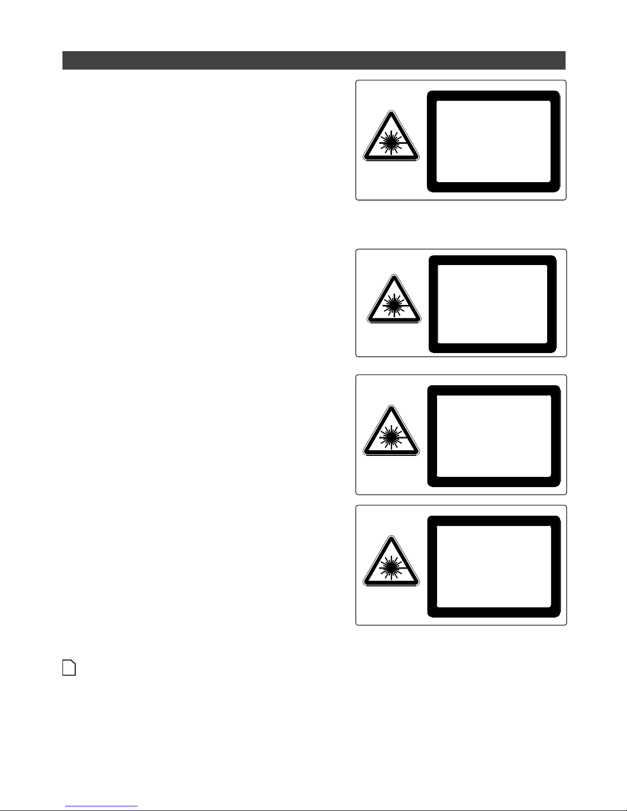
Class 3B laser components
Class 3B components are unsafe for eye exposure.
Usually only ocular protection will be required. Diffuse
reflections are safe if viewed for less than 10 seconds.
IEC 60825-1:2007
LASER RADIATION
AVOID EXPOSURE TO THE BEAM
CLASS 3B LASER PRODUCT
PEAK POWER:
EMITTED WAVELENGTH:
This product is designated for use solely as a
component and as such it does not fully comply
with the standards relating to laser products
specified in U.S. FDA CFR Title 21 part 1040
and IEC 60825-1
130 mW
660 nm
IEC 60825-1:2007
LASER RADIATION
AVOID EXPOSURE TO THE BEAM
CLASS 3B LASER PRODUCT
PEAK POWER:
EMITTED WAVELENGTH:
This product is designated for use solely as a
component and as such it does not fully comply
with the standards relating to laser products
specified in U.S. FDA CFR Title 21 part 1040
and IEC 60825-1
450 mW
808 nm
Labels reprinted here are examples only. For accurate specifications, refer to the label on your sensor.

Safety and Maintenance • 11Gocator 2000 & 2300 Series
Precautions and Responsibilities
Precautions specified in IEC 60825-1 and FDA CFR Title 21 Part 1040 are as follows:
Requirement Class 2M Class 3R Class 3B
Remote interlock Not required Not required Required*
Key control Not required Not required Required – cannot remove
key when in use*
Power-on delays Not required Not required Required*
Beam attenuator Not required Not required Required*
Emission indicator Not required Not required Required*
Warning signs Not required Not required Required*
Beam path Not required Terminate beam at useful
length
Terminate beam at useful
length
Specular reflection Not required Prevent unintentional
reflections
Prevent unintentional
reflections
Eye protection Not required Not required Required under special
conditions
Laser safety officer Not required Not required Required
Training Not required Required for operator and
maintenance personnel
Required for operator and
maintenance personnel
*LMI Class 3B laser components do not incorporate these laser safety items. These items must be added and completed by the
customer in their system design.
Class 3B Responsibilities
LMI Technologies has filed reports with the FDA to assist customers in achieving certification of laser
products. These reports can be referenced by an accession number, provided upon request. Detailed
descriptions of the safety items that must be added to the system design are listed below.
Remote Interlock
A remote interlock connection must be present in Class 3B laser systems. This permits remote switches
to be attached in serial with the keylock switch on the controls. The deactivation of any remote switches
must prevent power from being supplied to any lasers.
Key Control
A key operated master control to the lasers is required that prevents any power from being supplied to
the lasers while in the OFF position. The key can be removed in the OFF position but the switch must not
allow the key to be removed from the lock while in the ON position.
Power-On Delays
A delay circuit is required that illuminates warning indicators for a short period of time prior to supplying
power to the lasers.
Beam Attenuators
A permanently attached method of preventing human access to laser radiation other than switches,
power connectors or key control must be employed. On some LMI laser sensors, the beam attenuator is
supplied with the sensor as an integrated mechanical shutter.
Emission Indicator
It is required that the controls that operate the sensors incorporate a visible or audible indicator when
power is applied and the lasers are operating. If the distance between the sensor and controls is more
than 2 meters, or mounting of sensors intervenes with observation of these indicators, then a second
Safety and Maintenance • 12Gocator 2000 & 2300 Series
power-on indicator should be mounted at some readily-observable position. When mounting the warning
indicators, it is important not to mount them in a location that would require human exposure to the laser
emissions. User must ensure that the emission indicator, if supplied by OEM, is visible when viewed
through protective eyewear.
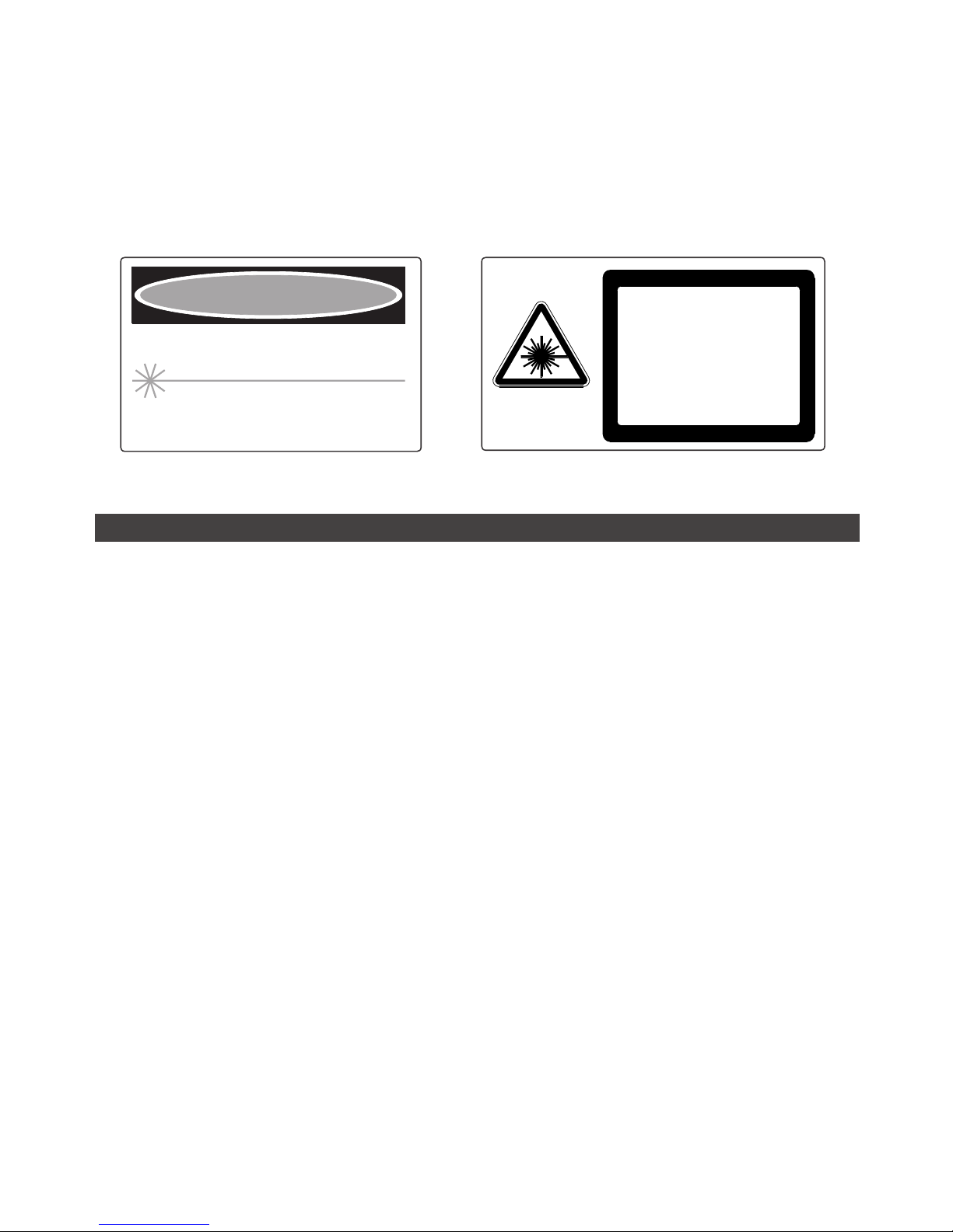
Warning Signs
Laser warning signs must be located in the vicinity of the sensor such that they will be readily observed.
Examples of laser warning signs are as follows:
PEAK POWER
WAVELENGTH
100mW
600-780nm
CLASS IIIb LASER PRODUCT
INVISIBLE AND/OR VISIBLE LASER RADIATION
AVOID DIRECT EXPOSURE TO BEAM
DANGER
FDA warning sign example
IEC 60825-1:2007
CAUTION
AVOID EXPOSURE
TO THE BEAM
CLASS 3B LASER LIGHT
IEC warning sign example
Systems Sold or Used in the USA
Systems that incorporate laser components or laser products manufactured by LMI Technologies require
certification by the FDA.
Customers are responsible for achieving and maintaining this certification.
Customers are advised to obtain the information booklet Regulations for the Administration and
Enforcement of the Radiation Control for Health and Safety Act of 1968: HHS Publication FDA 88-8035.
This publication, containing the full details of laser safety requirements, can be obtained directly from the
FDA, or downloaded from their web site at http://www.fda.gov/cdrh.

Safety and Maintenance • 13Gocator 2000 & 2300 Series
Electrical Safety
Sensors should be connected to earth ground
All sensors should be connected to earth ground through their housing. All sensors should be mounted
on an earth grounded frame using electrically conductive hardware to ensure the housing of the sensor
is connected to earth ground. Use a multi-meter to check the continuity between the sensor connector
and earth ground to ensure a proper connection.
Minimize voltage potential between system ground and sensor ground
Care should be taken to minimize the voltage potential between system ground (ground reference for
I/O signals) and sensor ground. This voltage potential can be determined by measuring the voltage
between Analog_out- and system ground. The maximum permissible voltage potential is 12 V but should
be kept below 10 V to avoid damage to the serial and encoder connections. Refer to Gocator 2000 I/O
Connector (page 337) and Gocator 2300 I/O Connector (page 345) for a description of connector
pins.
Use a suitable power supply
The +24 to +48 VDC power supply used with Gocator sensors should be an isolated supply with inrush
current protection or be able to handle a high capacitive load.
Use care when handling powered devices
Wires connecting to the sensor should not be handled while the sensor is powered. Doing so may cause
electrical shock to the user or damage to the equipment.
!
Failure to adhere to the guidelines described in this section may result in electrical shock or equipment
damage.

Safety and Maintenance • 14Gocator 2000 & 2300 Series
Environment and Lighting
Avoid strong ambient light sources
The imager used in this product is highly sensitive to ambient light hence stray light may have adverse
effects on measurement. Do not operate this device near windows or lighting fixtures that could influence
measurement. If the unit must be installed in an environment with high ambient light levels, a lighting
shield or similar device may need to be installed to prevent light from affecting measurement.
Avoid installing sensors in hazardous environments
To ensure reliable operation and to prevent damage to Gocator sensors, avoid installing the sensor in
locations;
• that are humid, dusty, or poorly ventilated
• with a high temperature, such as places exposed to direct sunlight
• where there are flammable or corrosive gases
• where the unit may be directly subjected to harsh vibration or impact
• where water, oil, or chemicals may splash onto the unit
• where static electricity is easily generated
Ensure that ambient conditions are within specifications
Gocator sensors are suitable for operation between 0 – 50 °C and 25 – 85% relative humidity (noncondensing). Measurement error due to temperature is limited to 0.015% of full scale per degree C.
The Master 200/400/800/1200/2400 is similarly rated for operation between 0 – 50 °C.
The storage temperature is -30 – 70 °C.
!
It is critical that the sensor is heat sunk through the frame it is mounted to. When a sensor is properly heat
sunk, the difference between ambient temperature and the temperature reported in the sensor's health
channel is less than 15 °C.
!
Gocator sensors are high accuracy devices. It is critical that the temperature of all of its components are in
equilibrium. When the sensor is powered up, a warm-up time of at least one hour is required in order to reach
a consistent spread of temperature within the sensor.
Sensor Maintenance
Keep sensor windows clean
Gocator sensors are high-precision optical instruments. To ensure the highest accuracy is achieved in all
measurements, the windows on the front of the sensor should be kept clean and clear of debris.
Use care when cleaning sensor windows
Use dry, clean air to remove dust or other dirt particles. If dirt remains, clean the windows carefully with a
soft, lint-free cloth and non-streaking glass cleaner or isopropyl alcohol. Ensure that no residue is left on
the windows after cleaning.
Turn off lasers when not in use
LMI Technologies uses semiconductor lasers in 3D measurement sensors. To maximize the lifespan of
the sensor, turn off the laser when not in use.

Safety and Maintenance • 15Gocator 2000 & 2300 Series
Avoid excessive modifications to files stored on the sensor
Settings for Gocator sensors are stored in flash memory inside the sensor. Flash memory has an
expected lifetime of 100,000 writes. To maximize lifetime, avoid frequent or unnecessary file save
operations.

16Gocator 2000 & 2300 Series
System Overview
Gocator sensors can be installed and used in a variety of scenarios. Sensors can be connected as
standalone devices, dual sensor (Main and Buddy) system, or multi-sensor system.
Standalone System
Standalone systems are typically used when only a single Gocator sensor is required. The sensor can
be connected to a computer’s Ethernet port for setup and can also be connected to devices such as
encoders, photocells, or PLCs.
GOCATOR I/O
CORDSET
ETHERNET
CORDSET
USER PC
(can be disconnected after setup)
GOCATOR
CONNECT POWER AND I/O AS
REQUIRED BY APPLICATION
IN - ENCODER / TRIGGER / SAFETY
OUT - SERIAL / ANALOG / DIGITAL
GOCATOR 2000 SERIES
Getting Started

Getting Started • 17Gocator 2000 & 2300 Series
GOCATOR
I/O CORDSET
POWER & ETHERNET
CORDSET
USER PC
(can be disconnected
after setup)
POWER: 24-48VDC @ 13W
LASER SAFETY: +24-48VDC TO ENABLE
WIRE RICH I/O
AS REQUIRED BY APPLICATION
IN - ENCODER / TRIGGER
OUT - SERIAL / ANALOG / DIGITAL
GOCATOR
GOCATOR 2300 SERIES

Getting Started • 18Gocator 2000 & 2300 Series
Dual Sensor System
In a dual sensor system, two Gocator sensors work together to perform profiling and output the
combined results. The controlling sensor is referred to as the Main sensor, and the helper is referred to
as the Buddy sensor. Gocator’s software recognizes three installation orientations – None, Opposite and
Wide.
For the Gocator 2000 series sensors, the Master 200 must be used to connect two sensors in a Dual
Sensor (Buddy) system. Gocator 20x0 I/O cordsets are used to connect sensors to the Master 200. The
Master 200 provides a single point of connection for system I/O and power. The Master 200 ensures
that the scan timing is precisely synchronized across sensors. Sensors and client computers typically
communicate via an Ethernet switch (minimum 100 Mbit/s).
MASTER 200
CAT5E ETHERNET
CABLE
GOCATOR I/O
CORDSET
ETHERNET
CORDSET
ETHERNET SWITCH
(NOT SUPPLIED
(BY LMI)
USER PC
MAIN GOCATOR
BUDDY GOCATOR
CONNECT I/O AS REQUIRED BY
APPLICATION
IN - ENCODER / TRIGGER / SAFETY
OUT - SERIAL / ANALOG / DIGITAL
GOCATOR 2000 SERIES
For the Gocator 2300 series sensors, a Master 400/800/1200/2400 must be used to connect two sensors
in a Dual Sensor (Buddy) system. Gocator 23x0 Master cordsets are used to connect sensors to the
Master.

Getting Started • 19Gocator 2000 & 2300 Series
GOCATOR I/O
CORDSET
GOCATOR
POWER AND ETHERNET
CORDSET
POWER, LASER SAFETY,
TRIGGER INPUTS, ENCODER
MAIN GOCATOR
BUDDY GOCATOR
GOCATOR 2300 SERIES
GIGABIT ETHERNET SWITCH
MASTER 400/800/1200/2400

Getting Started • 20Gocator 2000 & 2300 Series
Multi-Sensor System
Master 400/800/1200/2400 networking hardware can be used to connect two or more sensors into
a Multi-sensor system. Gocator Master cordsets are used to connect the sensors to a Master. The
Master provides a single point of connection for power, safety, encoder and digital inputs. A Master
400/800/1200/2400 can be used to ensure that the scan timing is precisely synchronized across
sensors. Sensors and client computers communicate via an Ethernet switch (minimum 100 Mbit/s).
Unlike the Master 200, Master 400/800/1200/2400 does not support digital, serial or analog output.
MASTER 400/800/1200/2400
USER PC
GIGABIT ETHERNET SWITCH
CAT5E ETHERNET CABLE
ETHERNET CORDSET
GOCATOR 2000 SERIES
POWER, LASER SAFETY,
TRIGGER INPUTS, ENCODER
GOCATOR
MASTER 400/800/1200/2400
USER PC
GIGABIT ETHERNET SWITCH
CAT5E ETHERNET CABLE
GOCATOR POWER AND ETHERNET
TO MASTER CORDSET
GOCATOR 2300 SERIES
POWER, LASER SAFETY,
TRIGGER INPUTS, ENCODER
GOCATOR

Getting Started • 21Gocator 2000 & 2300 Series
Hardware
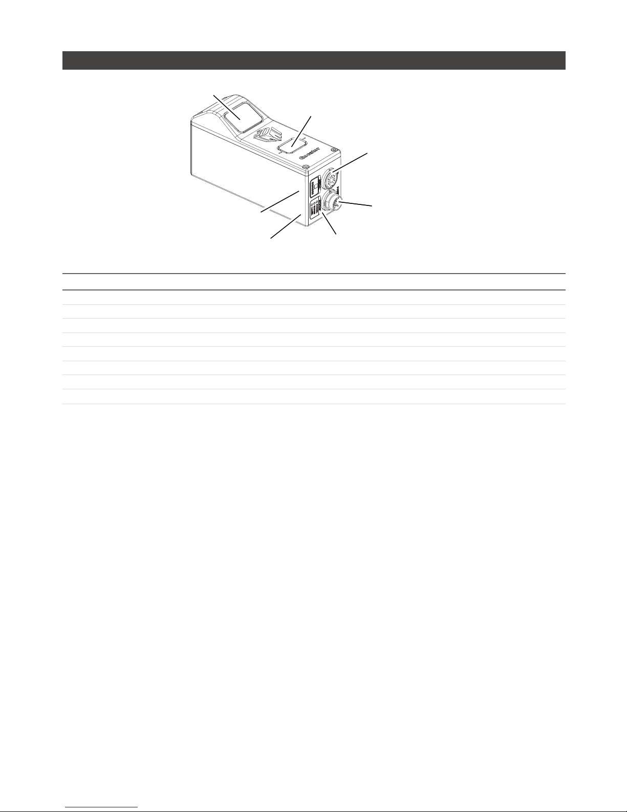
Gocator 2000 Sensor
CAMERA
LASER EMITTER
LAN CONNECTOR
I/O CONNECTOR
SERIAL NUMBER
POWER, RANGE, LASER
INDICATORS
Item Description
Camera Observes laser light reflected from target surfaces.
Laser Emitter Emits structured light for laser profiling.
I/O Connector Accepts power and input/output signals.
LAN Connector Connects to 100 Mbit/s Ethernet network.
Power Indicator Illuminates when power is applied (blue).
Range Indicator Illuminates when camera detects laser light and is within the target range (green).
Laser Indicator Illuminates when laser safety input is active (amber).
Serial Number Unique sensor serial number.
Getting Started • 22Gocator 2000 & 2300 Series
Gocator 2300 Sensor
CAMERA
LASER EMITTER
LAN CONNECTOR
I/O CONNECTOR
POWER/LAN CONNECTOR
SERIAL NUMBER
POWER, RANGE, LASER
INDICATORS
Item Description
Camera Observes laser light reflected from target surfaces.
Laser Emitter Emits structured light for laser profiling.
I/O Connector Accepts input and output signals.
Power / LAN Connector Accepts power and laser safety signals and connects to 1000 Mbit/s Ethernet network.
Power Indicator Illuminates when power is applied (blue).
Range Indicator Illuminates when camera detects laser light and is within the target range (green).
Laser Indicator Illuminates when laser safety input is active (amber).
Serial Number Unique sensor serial number.
Getting Started • 23Gocator 2000 & 2300 Series
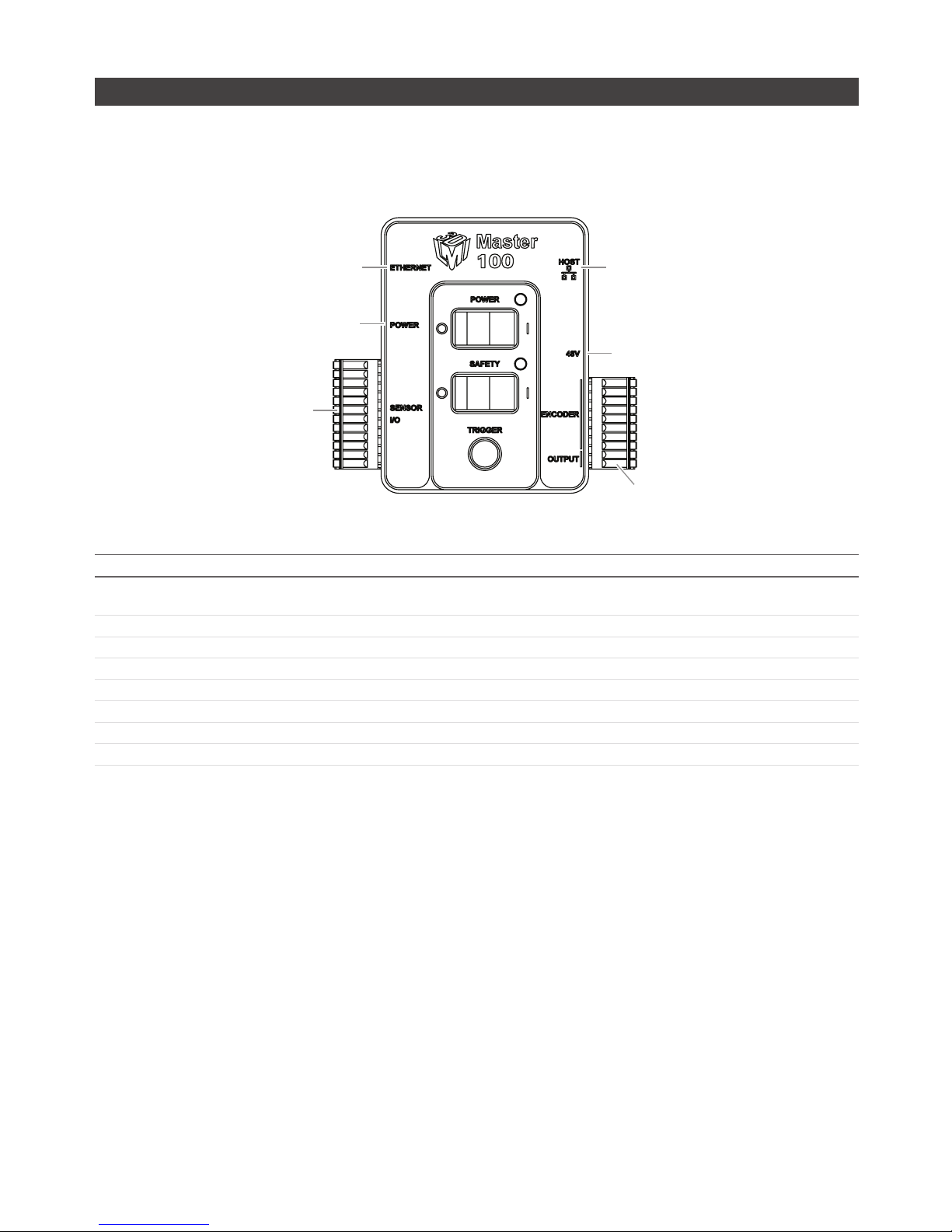
Master 100
The Master 100 is used by the Gocator 2300 series for standalone system setup. The Master 100 is
designed for development use only.
Sensor IO Port
3
Master Host Port
Master Power Port
Encoder/Output Port
Master Ethernet Port
48V Power Supply*
(Pin 1)
(Pin 1)
Item Description
Gocator Power Port Connects to the Gocator Power/LAN connector. Provides power and laser safety to the
Gocator.
Gocator Sensor I/O Port Connects to the Gocator I/O connector.
Laser Safety Switch Toggles laser safety signal provided to the sensors [O= laser off, I= laser on].
Power Switch Toggles sensor power.
Trigger Signals a digital input trigger to the Gocator.
Encoder Accepts encoder A, B and Z signals.
Digital Output Provides digital output.
Power Accepts power (+48 V).
Refer to Master 100 (page 350) for pinout details.
Getting Started • 24Gocator 2000 & 2300 Series
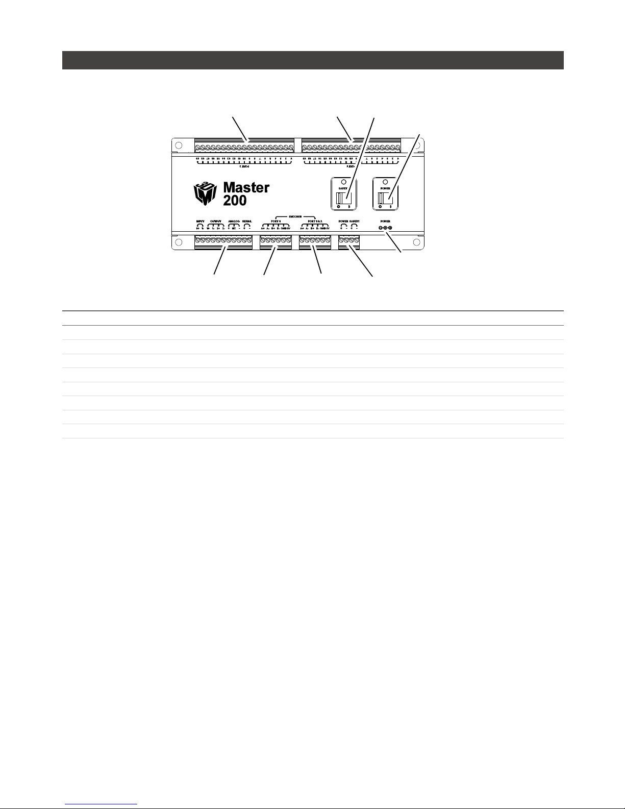
Master 200
The Master 200 supports standalone or dual sensor setup. It is only used by the Gocator 2000 series.
POWER SWITCH
CONNECTION TO SENSOR 1
CONNECTION TO SENSOR 2
LASER SAFETY SWITCH
INPUT/OUTPUT
ENCODER
(PORT 1 ONLY)
ENCODER
(PORT 1&2)
POWER AND
LASER SAFETY
POWER
(FOR DEMO USE ONLY*)
Item Description
Connection to Sensor 2 Gocator I/O connection for Sensor 2 (Buddy sensor).
Connection to Sensor 1 Gocator I/O connection for Sensor 1 (Main sensor).
Laser Safety Switch Toggles laser safety signal provided to the sensors [O= laser off, I= laser on].
Power Switch Toggles sensor power.
Input/Output Accepts digital input and provides digital output, serial output, and analog output.
Encoder (Port 1 only) Accepts encoder for Standalone sensor operation (Main sensor only).
Encoder (Port 1 & 2) Accepts encoder for Dual Sensor operation (Main and Buddy sensors).
Power and Laser Safety Accepts power (+24 to +48 V at 10 Watts) and laser safety inputs.
Refer to Master 200 (page 352) for pinout details.

Getting Started • 25Gocator 2000 & 2300 Series
Master 400/800
SENSOR PORTS 5-8
SENSOR PORTS 1-4
LED INDICATORS
MASTER 400 FRONT
MASTER 400 FRONT
MASTER 400/800 REAR
POWER AND SAFETY
ENCODER
INPUT
SENSOR PORTS 1-4
LED INDICATORS
Item Description
Sensor Ports Master connection for Gocator sensors (no specific order required).
Ground Connection Earth ground connection point.
Laser Safety Laser safety connection.
Encoder Accepts encoder signal.
Input Accepts digital input.
Refer to Master 400/800 (page 355) for pinout details.
Getting Started • 26Gocator 2000 & 2300 Series
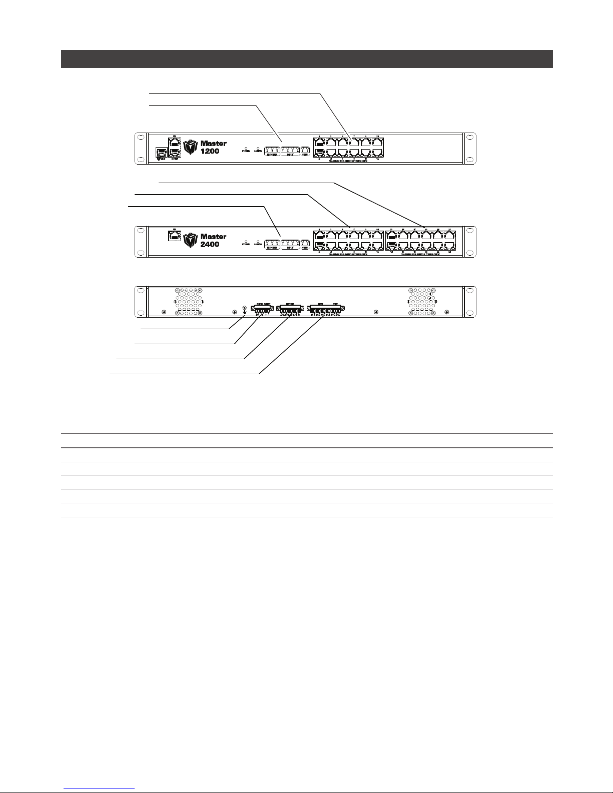
Master 1200/2400
SENSOR PORTS 13-24 (2400 ONLY)
SENSOR PORTS 1-12
LED INDICATORS
GROUND CONNECTION
POWER AND SAFETY
ENCODER
INPUT
SENSOR PORTS 1-12
LED INDICATORS
MASTER 1200 FRONT
MASTER 2400 FRONT
MASTER 1200/2400 REAR
Item Description
Sensor Ports Master connection for Gocator sensors (no specific order required).
Ground Connection Earth ground connection point.
Laser Safety Laser safety connection.
Encoder Accepts encoder signal.
Input Accepts digital input.
Refer to Master 1200/2400 (page 358) for pinout details.

Getting Started • 27Gocator 2000 & 2300 Series
Gocator 2000 Cordsets
Gocator 2000 sensors use three cordsets. The Ethernet cordset is used for sensor communication via
100 Mbit/s Ethernet with a standard RJ45 connector. The Gocator I/O cordset provides power and laser
safety interlock to sensors. It also provides digital I/O connections, an encoder interface, RS-485 serial
connection, and an analog output. The Gocator Master cordset provides electrical connection between
the sensor and a Master 400/800/1200/2400.
M12 ETHERNET CONNECTOR
4 PIN, D-CODE, MALE
RJ45 8 PIN JACK
CORDSET, GOCATOR, ETHERNET, Xm
M16 I/O CONNECTOR
19 PIN, MALE
PIGTAILED LEADS
CORDSET, GOCATOR I/O, Xm
RJ45 8 PIN JACK
M16 I/O CONNECTOR
19 PIN, MALE
CORDSET, GOCATOR, MASTER, Xm
The maximum cordset length is 60m. Refer to Gocator 2000 I/O Connector (page 337) for pinout
details. Refer to Parts and Accessories (page 360) for cordset lengths and part numbers. Contact LMI
for information on creating cordsets with customized length and connector orientation.
Gocator 2300 Cordsets
Gocator 2300 sensors use two types of cordsets. The Power & Ethernet cordset provides power, laser
safety locklock to the sensor. It is also used for sensor communication via 1000 Mbit/s Ethernet with
a standard RJ45 connector. The Gocator I/O cordset provides digital I/O connections, an encoder
interface, RS-485 serial connection, and an analog output. The Master version of the Power & Ethernet
cordset provides direct connection between the sensor and a Master 400/800/1200/2400.
M16 I/O CONNECTOR
19 PIN, MALE
PIGTAILED LEADS
M16 CONNECTOR
14 PIN, FEMALE
M16 CONNECTOR
14 PIN, FEMALE
PIGTAILED LEADS
CORDSET, GOCATOR I/O, Xm CORDSET, POWER & ETHERNET, Xm CORDSET, GOCATOR POWER & ETHERNET TO MASTER, Xm
RJ45 8 PIN JACK
RJ45 8 PIN JACK
RJ45 8 PIN JACK
The maximum cordset length is 60m. Refer to Gocator 2300 I/O Connector (page 345) and Gocator
2300 Power/LAN Connector (page 343) for pinout details. Refer to Parts and Accessories (page 360)
for cordset lengths and part numbers. Contact LMI for information on creating cordsets with custom
length or connector orientation.

Getting Started • 28Gocator 2000 & 2300 Series
Calibration Targets
Calibration targets are used for alignment calibration or travel calibration.
Calibration disks are typically used with systems containing a single sensor and can be ordered from
LMI Technologies. When choosing a disk for your application, select the largest disk that fits entirely
within the required field of view. Refer to Parts and Accessories (page 360) for calibration disk part
numbers.
100mm DIAMETER DISK
40mm DIAMETER DISK
For wide, multi-sensor systems, calibration bars are required to match the length of the system by
following the guidelines illustrated below. (LMI Technologies does not manufacture or sell calibration
bars.)
ONE HOLE PER SENSOR, CENTERED IN
EACH SENSOR’S FIELD OF VIEW.
DIAMETER MUST BE LARGE ENOUGH FOR
HOLE TO BE DETECTED BY SENSOR
(DEPENDS ON SENSOR RESOLUTION).
LENGTH OF BAR SHOULD BE GREATER
THAN THE COMBINED FIELD OF VIEW OF
ALL SENSORS.
HOLE DISTANCE (BETWEEN HOLES’ CENTERS).
Refer to Calibration (page 72) for more information on calibration procedures.

Getting Started • 29Gocator 2000 & 2300 Series
Installation
Grounding - Gocator
Gocators should be grounded to the earth/chassis through their housings and through the grounding
shield of the Power I/O cordset. Gocator sensors have been designed to provide adequate grounding
through the use of M5 x 0.8 pitch mounting screws. Always check grounding with a multi-meter to ensure
electrical continuity between the mounting frame and the Gocator's connectors.
!
It is imperative that the frame or electrical cabinet that the Gocator is mounted to is connected to earth
ground.
Grounding - Master 400/800/1200/2400
The mounting brackets of all Masters have been designed to provide adequate grounding through
the use of star washers. Always check grounding with a multi-meter by ensuring electrical continuity
between the mounting frame and RJ45 connectors on the front.
!
It is imperative that the frame or electrical cabinet that the Master is mounted to is connected to earth ground.
Getting Started • 30Gocator 2000 & 2300 Series
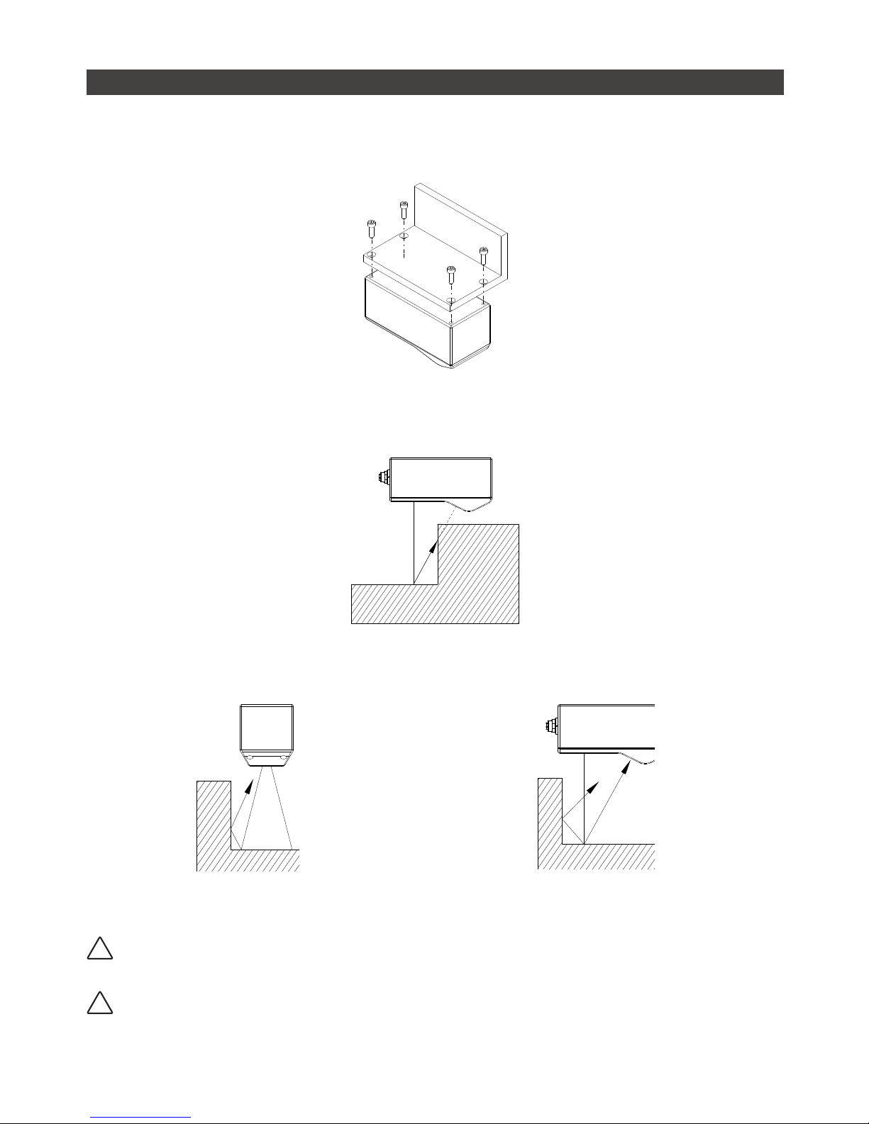
Mounting
Sensors should be mounted using four M5 x 0.8 pitch screws of suitable length. The recommended
thread engagement into the housing is 8 - 10 mm. Proper care should be taken in order to ensure that
the internal threads are not damaged from cross-threading or improper insertion of screws.
Sensors should not be installed near objects that might occlude a camera’s view of the laser.
Sensors should not be installed near surfaces that might create unanticipated laser reflections.
!
It is critical that the sensor is heat sunk through the frame it is mounted to. When a sensor is properly heat
sunk, the difference between ambient temperature and the temperature reported in the sensor's health
channel is less than 15 °C.
!
Gocator sensors are high accuracy devices. It is critical that the temperature of all of its components are in
equilibrium. When the sensor is powered up, a warm-up time of at least one hour is required in order to reach
a consistent spread of temperature within the sensor.
Getting Started • 31Gocator 2000 & 2300 Series
Orientations
The examples below illustrate the possible mounting orientations for standalone and dual sensor system.
For more information on orientations, refer to Dual Sensor System Layout (page 70).
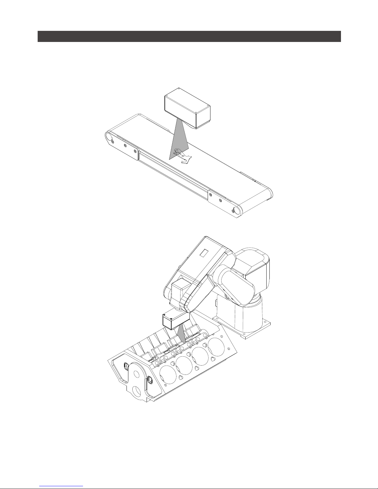
Single Sensor Orientations:
Single sensor above conveyor
Single sensor on robot arm

Getting Started • 32Gocator 2000 & 2300 Series
Dual Sensor System Orientations:
Side-by-side for wide-area measurement (Wide)
Main
Buddy
Main must be on the left side (when looking into the
connector) of the Buddy (Wide)
Above/below for two-sided measurement (Opposite)
Main
Buddy
Main must be on the top with Buddy on the bottom
(Opposite)

Getting Started • 33Gocator 2000 & 2300 Series
Software
User Interface Overview
Gocator sensors are configured by connecting to a Main sensor with a web browser. The Gocator web
interface is illustrated below.
1 2 3 4 5 6
10
8
9
7
Element Description
1 Connection Page For network configuration and maintenance.
2 Setup Page For configuring settings such as trigger source and exposure, and to perform
calibration steps.
3 Measurement Page For configuring measurements.
4 Output Page For configuring measurement result outputs to external devices.
5 Dashboard Page For viewing performance statistics and results.
6 Metric Panel Summarizes important performance statistics.
7 Help Online help resources, including User Manual, Firmware updates, and SDK.
8 Toolbar Controls sensor operation, manages configurations and replays recorded
measurement data.
9 Configuration Area Provides controls to configure profiling and measuring parameters.
10 Data Viewer Displays sensor data, tool setup controls, and measurements.

Getting Started • 34Gocator 2000 & 2300 Series
Connecting to a New Sensor
Sensors are shipped with the following default network configuration:
Setting Default
DHCP Disabled
IP Address 192.168.1.10
Subnet Mask 255.255.255.0
Gateway 0.0.0.0
All Gocator sensors are configured to 192.168.1.10 as the default IP address. For a dual sensor system, the
Main and Buddy sensors must be assigned unique addresses before they can be used on the same network.
Prior to proceeding, connect the Main and Buddy sensors one at a time (to avoid an address conflict) and use
the steps on page 38 to assign each sensor a unique address.
To connect to a sensor for the first time:
1 Connect cables and apply power.
Sensor cabling is illustrated in System Overview
(page 16)
GOCATOR I/O
CORDSET
ETHERNET
CORDSET
USER PC
(can be disconnected after setup)
GOCATOR
CONNECT POWER AND I/O AS
REQUIRED BY APPLICATION
IN - ENCODER / TRIGGER / SAFETY
OUT - SERIAL / ANALOG / DIGITAL
GOCATOR 2000 SERIES
GOCATOR
I/O CORDSET
POWER & ETHERNET
CORDSET
USER PC
(can be disconnected
after setup)
POWER: 24-48VDC @ 13W
LASER SAFETY: +24-48VDC TO ENABLE
WIRE RICH I/O
AS REQUIRED BY APPLICATION
IN - ENCODER / TRIGGER
OUT - SERIAL / ANALOG / DIGITAL
GOCATOR
GOCATOR 2300 SERIES

Getting Started • 35Gocator 2000 & 2300 Series
2 Change client network settings.
Windows 7:
» Open the Control Panel and select Network and
Sharing Center, then click Change Adapter Settings.
» Right-click the desired network connection, and
then click Properties.
» On the Networking tab, click Internet Protocol
Version 4 (TCP/IPv4), and then click Properties.
» Select “Use the following IP address” option.
» Enter IP Address “192.168.1.5” and Subnet Mask
“255.255.255.0”, then click OK.
Mac OS X v.10.6:
» Open the Network Pane in System Preferences and
select Ethernet.
» Set Configure to “Manually”.
» Enter IP Address “192.168.1.5” and Subnet Mask
“255.255.255.0”, then click Apply.
3 Enter the sensor's IP address 192.168.1.10 in a
web browser.
Firefox 3.5+, Chrome 4.0+, and Internet Explorer
8.0+ are supported. IMPORTANT! The Adobe Flash
browser plug-in, version 10.0+, must be installed.
http://192.168.1.10
4 Select the language
After selecting the language, the browser will
refresh and the web interface will display in the
selected language.
5 Press the Login button.
The Administrator password is initially blank.
Refer to Troubleshooting (page 312) if you experience any problems while attempting to establish a
connection to the sensor.
Getting Started • 36Gocator 2000 & 2300 Series
Running for the First Time
The Gocator is shipped with a default configuration that will produce laser ranges on most targets. The
following sections walk through the steps required to setup the sensor(s) to produce laser ranges.
Running a Standalone Sensor System
After the sensor is installed, laser profiling can be exercised to verify basic sensor operation.
To run a sensor for the first time:
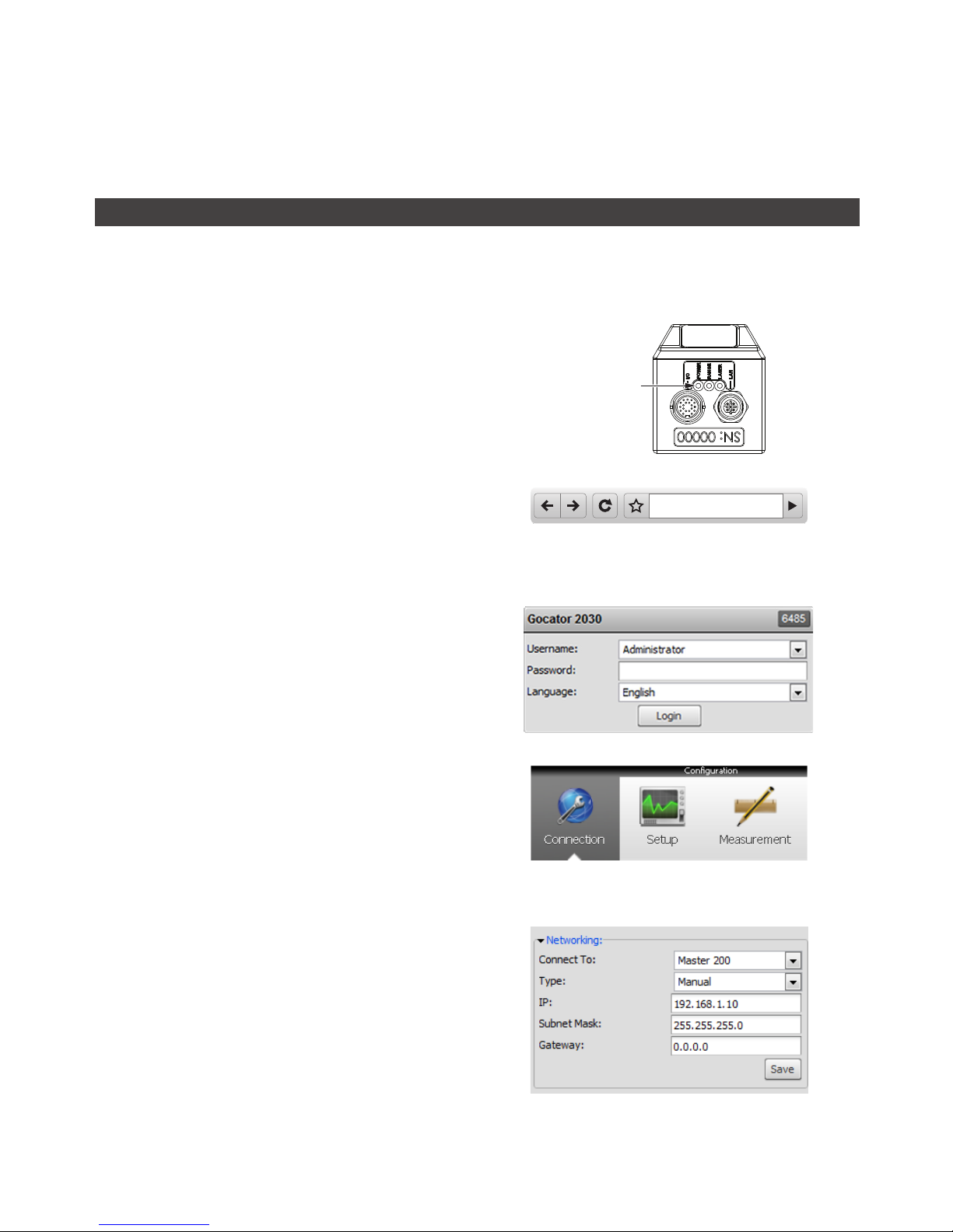
1 Power up the sensor.
The power LED (blue) should turn on immediately.
POWER LED
2 Enter the sensor's IP address 192.168.1.10 in a
web browser.
http://192.168.1.10
3 Login as Administrator with no password.
The interface display language can be changed
using the language option. After selecting the
language, the browser will refresh and the web
interface will display in the selected language.
4 Select the Connection Page.
5 Specify the Connect To setting.
The Connect To setting specifies whether the
sensor system is standalone, connected to a Master
200 or a Master 400/800/1200/2400. For single
sensor operations select Standalone or Master 200.

Getting Started • 37Gocator 2000 & 2300 Series
6 Ensure that the Data Source selector is
showing LIVE.
RECORD
SNAPSHOT
START
DATA SOURCE
7 Ensure that the Laser Safety Switch is enabled
or the Laser Safety input is high.
8 Select the Setup Page.
9 Press the Start button to start the sensor.
The Start button is used to run sensors
continuously, while the Snapshot button is used to
trigger a single profile.
Master 200
Master 400/800/1200/2400
Safety_in+
5V - 48VDC
Safety_in-
Standalone
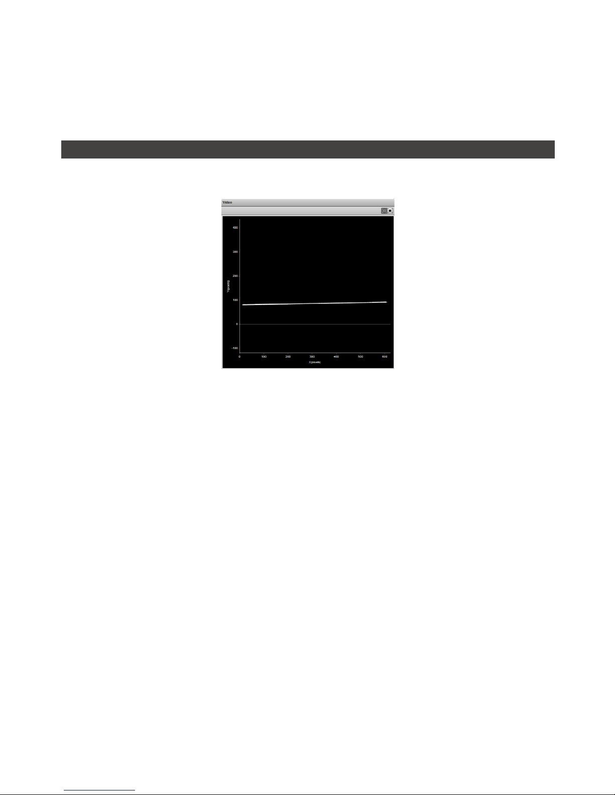
10 Move a target into the laser plane.
If a target object is within the sensor’s measurement
range, the Data Viewer will display the shape of
the target and the sensor’s range indicator LED will
illuminate.
If you cannot see the laser, or if a profile is
not displayed in the Data Viewer, refer to
Troubleshooting (page 312).
11 Press the Stop button.
You should now see the laser turns off.
RECORD
SNAPSHOT
STOP
DATA SOURCE
Getting Started • 38Gocator 2000 & 2300 Series
Running a Dual Sensor System
After the sensors are installed, laser profiling can be exercised to verify basic sensor operation.
If Master 200 is used and an encoder input is required, the encoder signals must be connected to the
Encoder (Port 1 & 2). Refer to Master 200 (page 24) for more details.
To run a dual sensor setup for the first time:
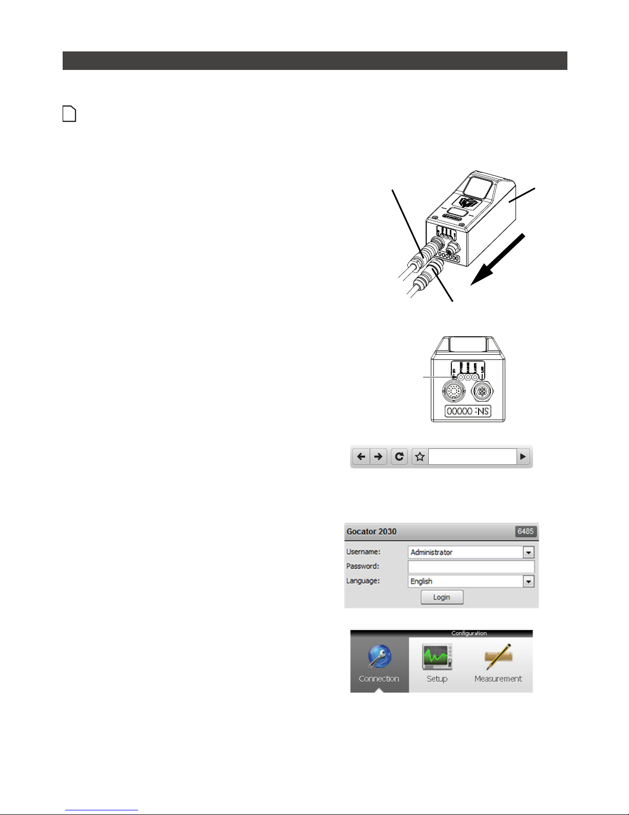
1 Turn off the sensors and unplug the Ethernet
network connection of the Main sensor.
All sensors are shipped with a default IP address of
192.168.1.10. Ethernet networks require a unique
IP address for each device. Skip step 1 to 3 if the
Buddy sensor's IP address is already setup with an
unique address.
MAIN
ETHERNET CORDSET
GOCATOR POWER I/O CORDSET
2 Power up the Buddy sensor.
The power LED (blue) of the buddy sensor should
turn on immediately.
POWER LED
3 Enter the sensor's IP address 192.168.1.10 in a
web browser.
This will log into the Buddy sensor.
http://192.168.1.10
4 Login as Administrator with no password.
5 Select the Connection Page.

Getting Started • 39Gocator 2000 & 2300 Series
6 Modify the IP address to 192.168.1.11 in the
Network settings and click the Save button.
When you click the Save button, you will be
prompted to confirm your selection.
7 Turn off the sensors, re-connect the Main
sensor's Ethernet connection and power-cycle
the sensors.
After changing network configuration, the sensors
must be reset or power-cycled before the change
will take effect.
MAIN
ETHERNET CORDSET
GOCATOR POWER I/O CORDSET
8 Enter the sensor's IP address 192.168.1.10 in a
web browser.
This will log into the Main sensor.
http://192.168.1.10
9 Login as Administrator with no password.
The interface display language can be changed
using the language option. After selecting the
language, the browser will refresh and the web
interface will display in the selected language.
10 Select the Connection Page.

Getting Started • 40Gocator 2000 & 2300 Series
11 Specify the Connect To setting.
The Connect To setting specifies whether the
sensor system is standalone, connected to a
Master 200 or a Master 400/800/1200/2400. For
dual sensor operation select Master 200 or Master
400/800/1200/2400.
12 Go to Connection Page > Available Sensors
panel.
The serial number of the Buddy sensor is listed in
the Available Sensors panel.
13 Select the Buddy sensor. Click the Assign
button.
The Buddy sensor will be assigned to the Main
sensor and its status will be updated in the System
panel
The firmware on Main and Buddy sensors must be
the same for Buddy assignment to be successful.
If the firmware is different, connect the Main and
Buddy sensor one at a time and follow the steps
in Firmware Upgrade (page 212) to upgrade the
sensors.
14 Ensure that the Data Source selector is
showing LIVE.
RECORD
SNAPSHOT
START
DATA SOURCE

Getting Started • 41Gocator 2000 & 2300 Series
15 Ensure that the Laser Safety Switch is enabled
or the Laser Safety input is high.
16 Select the Setup Page.
17 Press the Start button to start the sensors.
The Start button is used to run sensors
continuously, while the Snapshot button is used to
trigger a single profile.
Master 200 (for Gocator 2000)
Master 400/800/1200/2400 (for Gocator 2300)
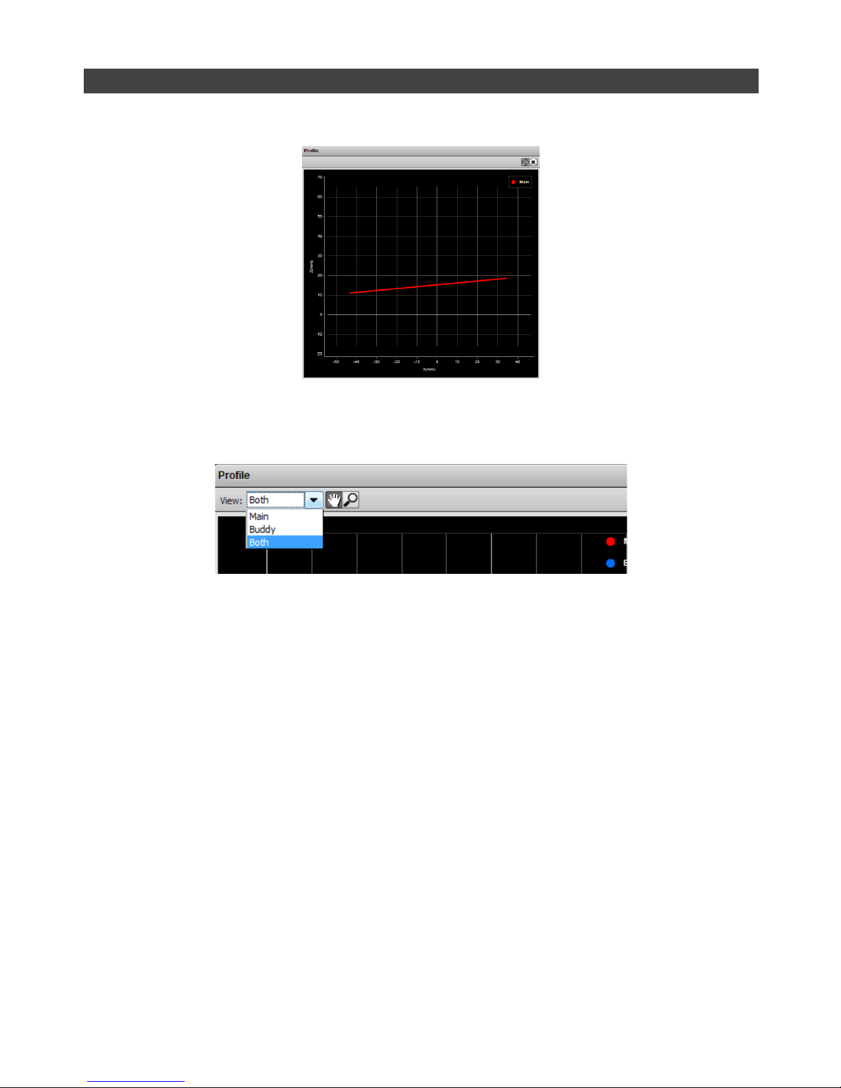
18 Move a target into the laser plane.
If a target object is within the sensor’s measurement
range, the Data Viewer will display the shape of the
target and the sensor’s Range Indicator LED will
illuminate.
Click the Main and Buddy button under the Setup
Page to view the profile data from the main and
buddy sensor
If you cannot see the laser, or if a profile is
not displayed in the Data Viewer, refer to
Troubleshooting (page 312).
19 Press the Stop button.
You should now see the lasers turn off.
RECORD
SNAPSHOT
STOP
DATA SOURCE

Getting Started • 42Gocator 2000 & 2300 Series
Next Steps
After completing the steps in this chapter, the Gocator measurement system is ready to be configured
for an application using the software interface. The interface is explained in the following chapters:
Setup and Calibration (page 43)
Fine tunes laser profiling for an application.
Measurement (page 82)
Programs measurements on sensors that are equipped with profile tools.
Output (page 182)
Profile data, measurements, and Pass/Fail results can be transmitted to external devices for process
control or data analysis.
Toolbar (page 193)
Controls system operation, record and playback data, and manages sensor configurations.
Dashboard (page 201)
Provides real-time monitoring of its health and measurement results.
Connection and Maintenance (page 205)
Setups the sensor connections, networking and performs maintenance tasks.

43Gocator 2000 & 2300 Series
Setup and Calibration
Setup Page
This chapter describes the steps to configure Gocator sensors for laser profiling using the Setup Page.
Setup and calibration steps should be performed before programming measurements or outputs.
1
2
3
4
5
6
7
Element Description
1 Operation Mode Panel Use the Operation Mode panel to set the current operation mode (Video, Profile, Part
or Raw) and other options.
2 Trigger Panel Use the Trigger panel to specify the trigger source and trigger related settings.
3 Sensor Panel Use the Sensor panel to specify settings for an individual sensor, such as active area
or exposure.
4 Layout Panel Use the Layout panel to configure the dual sensor system and to perform alignment or
travel calibration.
5 Filters Panel Use the Filters panel to specify settings for post processing of the profiles.
6 Part Detection Panel Use the Part Detection panel to set the part detection logic for sorting profiles into
discrete objects.

Setup • 44Gocator 2000 & 2300 Series
Element Description
7 Data Viewer Use the Data Viewer to display sensor data and adjust regions of interest. Depending
on the current operation mode, the data viewer can display video images, profile plots
or part views.
The following table provides quick references for specific goals that users could achieve from the panels
in the setup page.
Goal References
1 Select a trigger source that is appropriate for the application. Trigger (page 55)
2 Ensure that camera exposure is appropriate for laser profiling. Exposure (page 63)
3 Find the right balance between profile quality, speed, and CPU
utilization.
Active Area (page 60)
Exposure (page 63)
Resolutions (page 67)
4 Specify mounting orientations for dual sensor systems. Dual Sensor System Layout (page
70)
5 Calibrate the system so that laser profile data can be aligned to a
common reference and values can be correctly scaled in the axis of
motion.
Alignment Calibration (page 73)
Travel Calibration (page 74)
6 Specify smoothing, gap-filling and resampling parameters to remove
effects of occlusions.
Filters (page 76)
7 Setup the part detection logic to sort profiles into discrete objects. Part Detection (page 80)

Setup • 45Gocator 2000 & 2300 Series
Operation Modes
The Gocator web interface supports four operation modes: Video, Profile, Raw and Whole Part. The
operation mode can be selected in the Operation Mode panel.
Mode and Option Description
Video Output video images from the Gocator. This mode is useful for configuring exposure
time and troubleshooting stray light or ambient light problems.
Profile Output profiles and perform profile measurements. Video images are processed
internally to produce laser profiles and cross-sectional measurements.
Whole Part Output 3D point clouds and perform part measurements. Laser profiles are sorted
into discrete parts. The parts are then processed internally to produce measurements
. "Whole Part" is often referred to as "Part" in the Gocator web interface and in this
document.
Raw Output profiles. In Raw Mode, video images are processed internally by the sensor
to produce laser profiles. Use this mode to extract unprocessed ranges from the
Gocator at the highest possible rate. Post-profiling processing and measurements are
disabled.
Acquire Intensity When enabled, an intensity value will be produced for each laser profile point.
Setup • 46Gocator 2000 & 2300 Series
Data Viewer
The Data Viewer can display video images, profile plots, intensity images and height maps. It is also
used to configure active area and measurement tools. Its use is dependent on the current operation
mode and the panel selection.
Video Mode
The Data Viewer displays camera images. In a dual sensor system, camera images from the Main or the
Buddy sensor can be displayed.
To select the view of the display:
1 Navigate to the Setup Page.
2 Select the View.
Select the Main or the Buddy sensor from the drop-down list at the top of the Data Viewer.
Setup • 47Gocator 2000 & 2300 Series
Profile and Raw Mode
In Profile and Raw mode, the Data Viewer displays profile plots.
In a dual sensor system, profiles from individual sensors or from a combined view can be displayed.
While in the Setup Page, selecting a panel (e.g. Sensor Panel or Layout Panel) will automatically set the
display to the most appropriate display view.
To manually select the display view in the Setup Page:
1 Navigate to the Setup Page.
2 Select the View.
An individual sensor or the combined view can be selected from the drop-down list at the top of the Data
Viewer.
In the Measurement Page, the view of the display is set to the Profile Source of the selected
measurement tool (page 86).

Setup • 48Gocator 2000 & 2300 Series
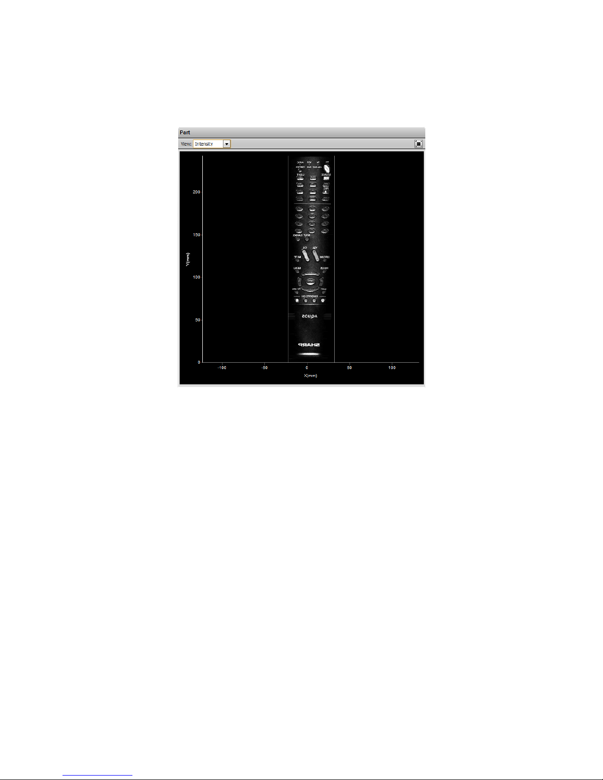
Whole Part
In addition to displaying profiles, the Data Viewer can display height maps and intensity images of the
detected objects. Users select the data to display from the View option.
Users can use the 3D button to view Whole Part data in 3D viewer. The 3D model is overlaid with the
information selected in the View option.
View Option
View Option Information
Profile Only available in 2D view. Plots the last collected profile.
Heightmap In 2D view, displays the pseudo color height map.
In 3D view, overlays the 2D pseudo-color map ion the 3D model.
Uniform Only available in 3D view. Overlays a uniform shaded surface on the 3D model.
Intensity In 2D view, display the intensity.
In 3D view, overlays the intensity map on the 3D model.
Choosing the Profile view option will switch the data viewer out of the 3D viewer and display the profile
plot.
2D viewer for height map 2D viewer for intensity

Setup • 49Gocator 2000 & 2300 Series
3D viewer with height map overlay 3D viewer dwith intensity overlay
3D data viewer with uniform overlay
Users can toggle between 2D and 3D viewer by clicking on the 3D button. Refer to Data Viewer Controls
(page 50) for explanations on the available controls.
In a dual sensor system, data from individual sensors or from a combined view can be selected. While
in the Setup Page, selecting a panel (e.g. Sensor Panel, Layout Panel or Part Detection panel) will
automatically set the display to the most appropriate display type and display view.
To manually select the display type and the display view in the Setup Page:
1 Navigate to the Sensor Page.
2 Select the View.
Profile, Height map, uniform and Intensity can be selected from the left drop-down list. An individual sensor
or the combined view can be selected from the right drop-down list.

Setup • 50Gocator 2000 & 2300 Series
Region Definition
The Data Viewer can also be used to define a region of interest.
To setup a region of interest:
1 Move the mouse cursor to the rectangle.
The rectangle is automatically displayed when a setup or measurement requires an area to be specified.
2 Drag the rectangle to move it, and use the handles on the rectangle’s border to resize it.
Data Viewer Controls
The data viewer is controlled by mouse clicks and by the buttons on the display tool bar. The mouse
wheel can be also be used for zooming in and out.
Press 'F' when the cursor is in the data viewer to change into full screen.
1:1 Aspect Ratio Reset Zoom
Scaling Setting
Toggle 3D Mesh
Pan
Zoom in / out

Setup • 51Gocator 2000 & 2300 Series
Height Map Color Scale
Height maps are displayed in pseudo-color; the height (Z) axis is color coded. The scaling of the colors
to the height values can be adjusted.
To change the scaling of the height map:
1 Select Height Map from the View setting.
2 Click the Scaling button.
This will bring up the range scaling dialog box. To manually set the scale, uncheck the Auto Range option.
Enter the minimum and maximum height to which the colors will be mapped.

Setup • 52Gocator 2000 & 2300 Series
Profile Output
Goactor measures the height of the object calculated from laser triangulation. The Gocator reports a
series of ranges along the laser line, with each range representing the distance from the sensor's origin
plane. Each range contains a height and a position in the sensor's field of view.
Coordinate Systems
Range data is reported in sensor or system coordinates depending on the calibration state. The
coordinate systems are described below.
Sensor Coordinates
Prior to calibration, individual sensors use the
coordinate system shown here.
The z-axis represents the sensor’s measurement range
(MR), with the values increasing towards the sensor.
The x-axis represents the sensor’s field of view (FOV).
The origin is at the center of the MR and FOV.
In Part data, the Y-axis represents the relative position of
the part in the direction of travel. y-position increases as
the object moves forward (increasing encoder position).
Z
X
System Coordinates
Alignment calibration or travel calibration can be used
to establish a common coordinate system for the
Main and Buddy sensors. Calibration determines the
adjustments to X, Z, and Tilt (rotation in the X–Z plane)
required to align the data from each sensor.
System coordinates are aligned such that the system
x-axis is parallel to the calibration target surface. The
system Z-origin is set to the base of the calibration
target object. The Tilt angle is positive when rotating
from the X to the Z axis.
Similar to the sensor coordinates, y-positions increases
when the encoder increases.
For Wide and Opposite layouts, profiles and
measurements from the Main and Buddy sensors are
expressed in a unified coordinate system. Isolated
layouts express results using a separate coordinate
system for each sensor.
Z
X
Z
X
MAIN BUDDY
MAIN
Setup • 53Gocator 2000 & 2300 Series
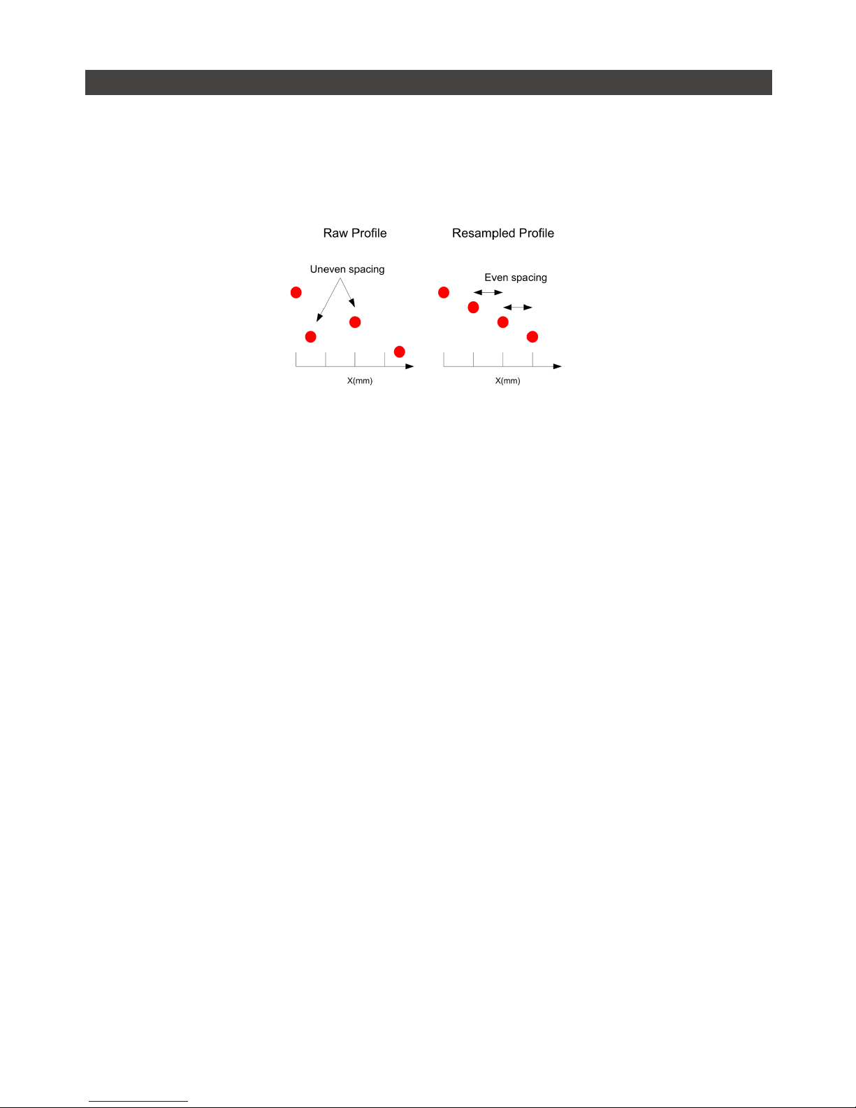
Resampled And Raw Profile Format
Profile data produced by Profile or Part mode are processed differently than by Raw Mode. In Profile or
Part mode, the ranges are resampled to an even interval along the laser line (x-axis). The resampling
divides the x-axis into fixed size "bins" at even intervals. Profile points that fall into the same bin will be
combined into a single range value (z). The size of the resampling interval can be configured in the
Filters panel (page 76).
In the Ethernet data channel, only the range values (z) are reported and the x-positions can be
reconstructed through the array index at the receiving end (the client).
Resampling reduces the complexity for downstream algorithms to process the profile data from the
Gocator, but at the cost of higher processing load on the sensor’s CPU.
In contrast, Raw Mode outputs unprocessed range data. Ranges are reported in (x,z) coordinate pairs,
freeing up processing resources in the Gocator, but typically requiring more complicated processing on
the client side.
All built-in measurement tools in the Gocator operate on resampled data in Profile or Part Mode.
Setup • 54Gocator 2000 & 2300 Series
Intensity Output
Gocator sensors can produce intensity images that measure the amount of light reflected by an object.
An 8-bit intensity value is output for each range value along the laser line. Gocator applies the same
coordinate system and resampling logic as the ranges (page 52) to the intensity values.

Setup • 55Gocator 2000 & 2300 Series
Trigger
A trigger is an event that causes a sensor to take a single picture. When a trigger is processed, the laser
is strobed and the camera exposes to produce an image. The resulting image is processed inside the
sensor to yield a laser profile (range/distance information), which can then be used for measurement.
The laser and camera inside a sensor can be triggered by one of four sources:
Trigger Source Description
Time Sensors have an internal clock that can be used to generate fixed-frequency triggers.
The external input can be used to enable or disable the time triggers.
Encoder An encoder can be connected to provide triggers in response to motion. Three
encoder triggering behaviors are supported:
1. Ignore Backward
A scan is triggered only when the target object moves forward. If the target object
moves backward, it must move forward by at least the distance of one encoder spacing
to trigger a scan.
2. Track Backward
A scan is triggered when the target object moves forward. If the target object moves
backward, it must move forward by at least the distance that the target travelled
backward, plus one encoder spacing, to trigger a scan.

Setup • 56Gocator 2000 & 2300 Series
Trigger Source Description
Encoder 3. Bi-directional
A scan is triggered when the target object moves forward or backward.
When triggers are received at a frequency higher than the maximum frame rate, some
triggers may not be accepted. The Trigger Drops Indicator in the Dashboard can be
used to check for this condition.
The external input can be used to enable or disable the encoder triggers.
Refer to Encoder Input (page 341) for more information on connecting the encoder to
Gocator sensors.
External Input A digital input can provide triggers in response to external events (e.g. photocell).
When triggers are received at a frequency higher than the maximum frame rate, some
triggers may not be accepted. The Trigger Drops Indicator in the Dashboard can be
used to check for this condition.
Refer to Digital Inputs (page 340) for more information on connecting external input to
Gocator.
Software A network command can be used to send a software trigger. Refer to Gocator Protocol
(page 253) for more information.
Setup • 57Gocator 2000 & 2300 Series
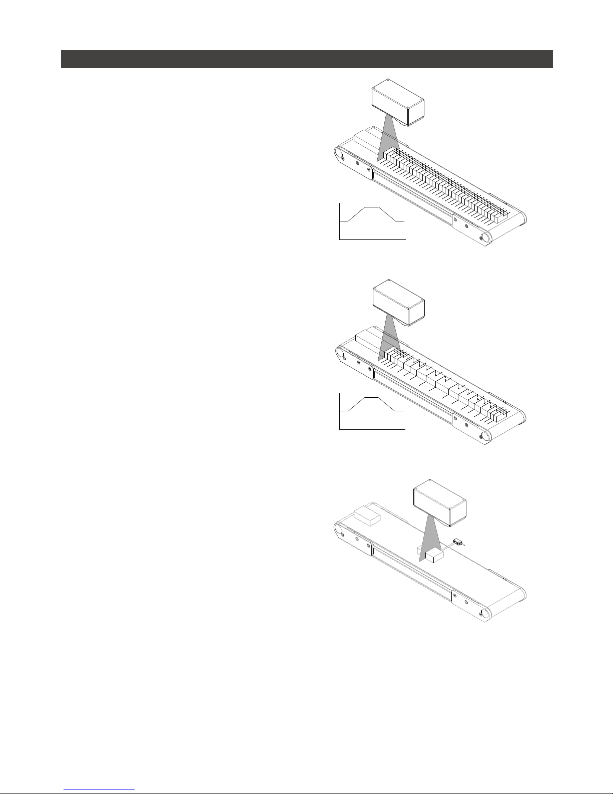
Examples
Example: Encoder + Conveyor
Encoder triggering is used to perform profile
measurements at a uniform spacing.
The speed of the conveyor can vary while the object
is being measured; an encoder ensures that the
measurement spacing is consistent, independent of
conveyor speed.
Conveyor Speed
Time
Example: Time + Conveyor
Time triggering can be used instead of encoder
triggering to perform profile measurements at a fixed
frequency.
Measurement spacing will be non-uniform if the
speed of the conveyor varies while the object is being
measured.
It is strongly recommended to use an encoder with
transport-based systems due to the difficulty in
maintaining constant transport velocity.
Conveyor Speed
Time
Example: External Input + Conveyor
External Input triggering can be used to produce a
snapshot for profile measurement.
For example, a photocell can be connected as an
External Input to generate a trigger pulse when a
target object has moved into position.
An External Input can also be used to gate the trigger
signals when Time or Encoder triggering is used. For
example, a photocell could generate a train of trigger
pulses as long as there is a target in position.

Setup • 58Gocator 2000 & 2300 Series
Example: Software Trigger + Robot Arm
Software triggering can be used to produce a
snapshot for profile measurement.
A software trigger can be used in systems that
employ external software to orchestrate the activities
of system components.

Setup • 59Gocator 2000 & 2300 Series
Settings
The trigger source is selected using the Trigger panel in the Setup page.
After specifying a trigger source, the Trigger Panel will show the parameters that can be configured.
Parameters Trigger Source Description
Trigger All Selects the trigger source. (Time, Encoder, External Input, or Software)
Max Frame Rate All Reports the maximum frame rate, which is a function of the current Active
Area, Exposure, and Resolution settings.
Frame Rate Time The Frame Rate setting can be used to control the frame rate. Select the
Max check box to lock to the maximum frame rate. Fractional values are
supported. For example, 0.1 can be entered to run at 1 frame every 10
seconds.
Gate using External
Input
Time, Encoder External input can be used to enable or disable profiling in a sensor. When
enabled, the sensor will respond to time or encoder triggers only when the
external input is asserted.
Refer to Digital Inputs (page 340) for more information on connecting
external input to a Gocator senor.
Travel Speed Time Travel Speed provides proper scaling in the y-axis (axis of motion). Travel
Speed can be calculated automatically by performing Travel Calibration or
set manually after clicking on the unlock button.
Encoder Behavior Encoder Encoder Behavior setting is used to specify how the Gocator sensor is
triggered when the target moves.
Encoder Resolution Encoder Encoder Resolution (millimeters per tick) provides proper scaling in the y-axis
(axis of motion). The encoder resolution can be calculated automatically by
performing Travel Calibration or set manually after clicking on the unlock
button.
Spacing Encoder Encoder Spacing setting is used to specify the distance between triggers
(mm). Internally the Gocator sensor rounds the spacing to a multiple of the
encoder resolution.
Units External Input,
Software
Units specifies whether the trigger delay, output delay and output scheduled
command operates in the time or the encoder domain. The unit is implicitly
set to microseconds with Time trigger source, and millimeters with Encoder
trigger source.
Trigger Delay External Input Trigger delay can be used to control the time or spacing the sensor
waits before a frame after the external input is activated. This is used to
compensate for the positional difference between the source of the external
input trigger (e.g. photocells) and the sensor.
Trigger delay is only supported in the single exposure mode (page 63).
Setup • 60Gocator 2000 & 2300 Series
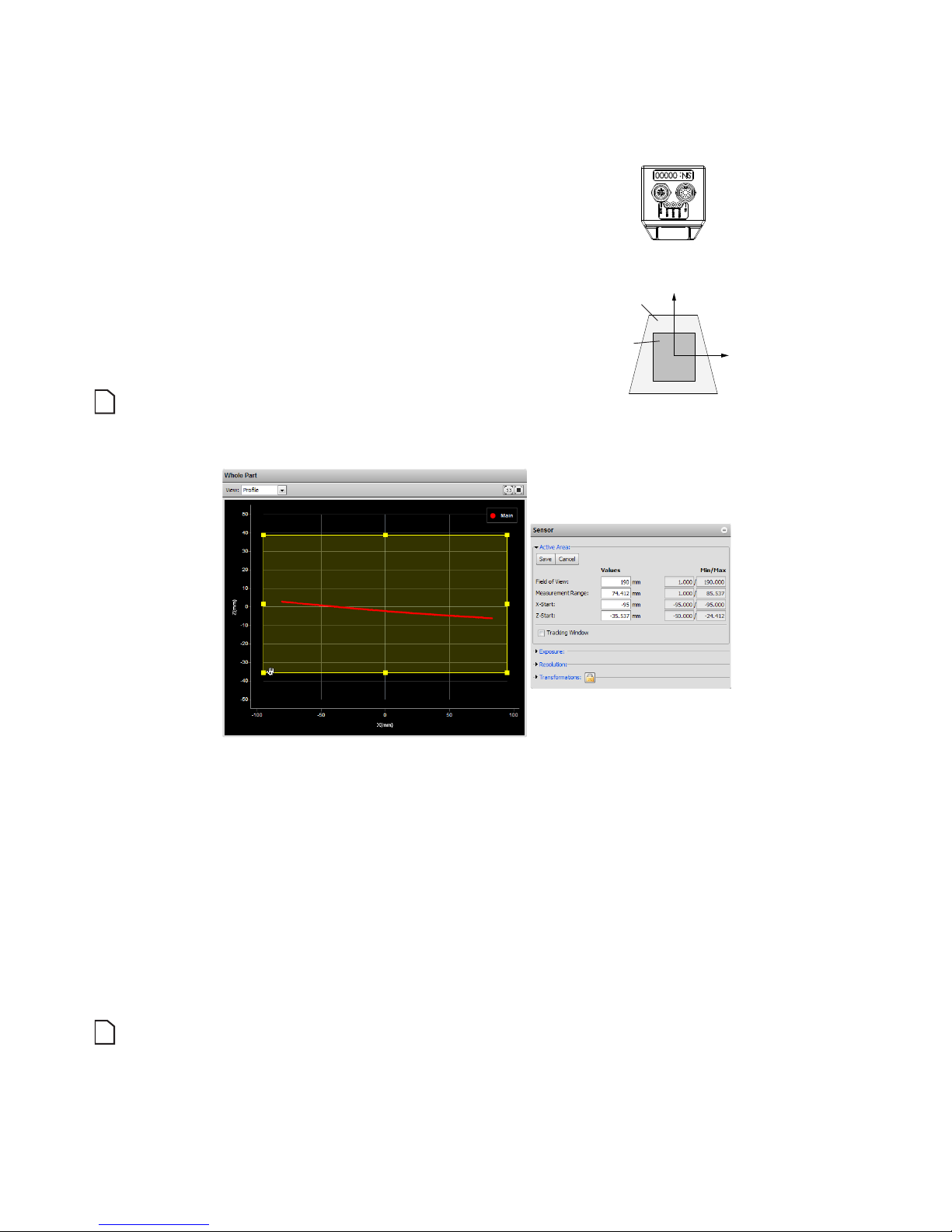
Active Area
Active area refers to the region within the sensor’s maximum field of view that is used for laser profiling.
By default, the active area covers the sensor’s
entire field of view. By reducing the active area,
the sensor can operate at higher speeds.
Active area is specified in sensor coordinates,
rather than in system coordinates. As a
result, active area must be configured before
Alignment or Travel calibration is performed.
Refer to Coordinate Systems (page 52)
for more information on sensor and system
coordinates.
Active Area can only be set when the sensor is not
calibrated.
Z
X
FIELD OF VIEW
ACTIVE AREA
To set the active area:
1 Navigate to the Sensor panel.
Active area is specified separately for each sensor. Click the arrow next to Active Area to expand the
panel.
2 Click the Select button.
If the Select Active Area button is disabled, then calibration may need to be cleared. Refer to Clearing
Calibration (page 75) in this chapter for information on clearing calibration.
3 Position and resize the Active Area rectangle shown in the Data Viewer.
4 Click the Save button.
Laser profiling devices are usually more accurate at the near end of the measurement range. If your
application requires a measurement range that is small relative to the maximum measurement range of the
sensor, mount the sensor such that the active area can be specified at the near end of the measurement
range.
Setup • 61Gocator 2000 & 2300 Series
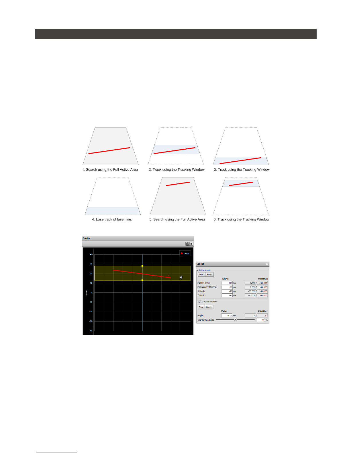
Tracking Window
The Gocator can track a relatively flat object in real-time to achieve very high scan rates. This feature
is based on tracking the object height using a small window, called the Tracking Window, that moves
dynamically to cover a larger measurement range. Users can balance the gain in speed and the tracking
ability by configuring the size of the tracking area. This feature is typically used in road or web scanning
applications where the target is a continuous flat surface.
A laser line remains tracked as long as the percentage of detected laser point exceeds the user defined
search threshold. When the sensor loses track of the laser line, the sensor will search for the laser line
using the full active area.
Tracking Window is only supported on the Gocator 2300 series.

Setup • 62Gocator 2000 & 2300 Series
To enable tracking window:
1 Check the Tracking Window box.
Checking the Tracking Window box expands the panel to reveal the settings for the window used to track
the object height.
2 Resize the Tracking Window shown in the Data Viewer.
Only the height of the window is required. User can move the position of the tracking window to cover a
live profile to help adjust the window height.
3 Edit the Search Threshold setting.
The search threshold defines the minimum percentage of the points detected across the profile for the
laser to be considered tracked. If the tracking is lost, the sensor will search for the laser using the full
active area.
The sensor adjusts the position of the tracking window such that the area is centered around the
average height of the entire visible laser profile. Users should adjust the lighting and the active area to
remove all background objects (i.e. conveyer belt surface, ambient lights).
Setup • 63Gocator 2000 & 2300 Series
Exposure
Exposure determines the duration of camera and laser on-time. Longer exposures can be helpful to
detect laser signals on dark or distant surfaces, but increasing exposure time decreases the maximum
speed. Different target surfaces could require different exposures for optimal results. Gocator sensors
provide three exposure modes for the flexibility needed to scan different types of target surfaces.
Exposure Mode Description
Single Exposure Uses single exposure for all objects. Used when the surface is
uniform and is the same for all targets.
Dynamic Exposure Automatically adjust the exposure after each frame. Used when the
target surface varies between scans.
Multiple Exposures Uses multiple exposures to create a single profile. Used when the
target surface has a varying reflectance within a single profile (e.g.
white and black color)
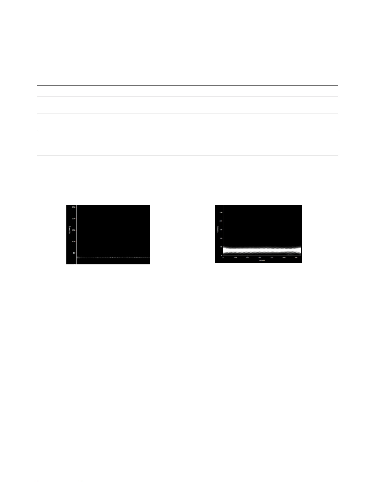
Video mode enables you to see how the laser appears on the camera and to identify any stray light
or ambient light problems. When exposure is tuned correctly, the laser line should be clearly visible
along the entire length of the viewer. If it is too dim, increase the exposure value; if it is too bright
decrease exposure value.
Under exposure
Laser line is not detected.
Increase the exposure value.
Over exposure
Laser line is too bright.
Decrease the exposure value.
In a dual sensor system, the Main and the Buddy sensor must use the same exposure mode or the
system will fail to start.

Setup • 64Gocator 2000 & 2300 Series
Single Exposure
The sensor uses a fixed exposure in every scan. The is used when the target surface is uniform and is
the same for all parts.
To enable single exposure:
1 Place a representative target in view of the sensor.
The target surface should be similar to the material that will normally be measured.
2 Select Profile, Part or Raw Mode.
3 Navigate to the Sensor panel.
Click the arrow next to Exposure to expand the panel. Click the Main or Buddy sensor button to select the
sensor.
4 Select Single.
5 Edit the Exposure setting.
The auto-set function can be used to automatically tune the exposure. Press the Auto Set button and the
sensor will turn on and automatically tune the exposure time.
6 Run the sensor and check that laser profiling is satisfactory.
If not satisfactory, adjust the exposure values manually. Switch to Video mode to use video to help tune the
exposure (page 62).

Setup • 65Gocator 2000 & 2300 Series
Dynamic Exposure
The sensor automatically uses past profile information to adjust the exposure to yield the best profile.
This is used when the target surface changes from scan to scan.
To enable dynamic exposure:
1 Select Profile, Part or Raw Mode.
2 Navigate to the Sensor panel for the Main or Buddy sensor.
Click the arrow next to Exposure to expand the panel. Click the Main or Buddy button to select the sensor.
3 Select Dynamic.
4 Set the minimum and maximum exposure.
The auto-set function can be used to automatically set the exposure. First, place the brightest target in
the field of view and press the Auto Set Min button to set the minimum exposure. Then, place the darkest
target in the field of view and press the Auto Set Max button to set the maximum exposure.
5 Run the sensor and check that laser profiling is satisfactory.
If not satisfactory, adjust the exposure values. Switch to Video mode to use video to help tune the exposure
(page 62).

Setup • 66Gocator 2000 & 2300 Series
Multiple Exposures
The sensor combines data from multiple exposures to create a single laser profile. Multiple exposures
can be used to increase the ability to detect light and dark materials that are in the field of view
simultaneously.
Up to five exposures can be defined with each set to a different exposure level. For each exposure the
sensor will perform a complete scan at the current frame rate making the effective frame rate slower. For
example, if two exposures are selected then the speed will be halved of the single exposure frame rate.
The sensor will perform a complete scan for each external input or encoder trigger.
The resulting profile is a composite created by combing data collected with different exposures.
The sensor will choose profile data that is available from the lowest numbered exposure step. It is
recommended to use larger exposure for higher numbered step.
Users must ensure the exposure steps set for composite exposure are the same between the Main and Buddy
sensors in Dual Sensor Mode.
To enable multiple exposures:
1 Select Profile, Part or Raw Mode.
2 Navigate to the Sensor panel.
Click the arrow next to Exposure to expand the panel. Click the Main or Buddy button to select the sensor.
3 Select Multiple.
4 Press the + button to add an exposure step.
Up to a maximum of five exposure settings can be added.
5 Set the exposure level to make the Gocator less or more sensitive (as required).
The auto-set function can be used to automatically set the exposure. To use the auto-set function, place
target material in the field of view then select an exposure step and press the Auto Set button. Repeat this
procedure for each exposure step.
6 Select the exposure step used for intensity output
If intensity acquisiton is enabled, select the exposure step that is used to capture the intensity output.
7 Run the sensor and check that laser profiling is satisfactory.
If not satisfactory, adjust the exposure values. Switch to Video mode to help tune the exposure (page
62).

Setup • 67Gocator 2000 & 2300 Series
Resolutions
Resolutions can be set independently for the x-axis and z-axis. Reducing the resolution increases speed
or reduces CPU utilization while maintaining the sensor's field of view.
X Resolution
The X Resolution setting can be used to decrease the profile's x-resolution in order to decrease sensor
CPU utilization. The X Resolution setting works by reducing the number of image columns used for laser
profiling.
The CPU Load bar at the top of the interface displays how much of the CPU is being utilized.
To configure X resolution:
1 Navigate to the Sensor panel.
Click the arrow next to Resolution to expand the panel. Click the Main or Buddy button to select the sensor.
X resolution is specified separately for each sensor.
2 Select a resolution value.
X resolution values are expressed as fractions. For example, a resolution value of 1/2 indicates that every
second camera column will be used for laser profiling.
3 Check that laser profiling is satisfactory.
After adjusting the resolution, confirm that laser profiling characteristics are satisfactory.

Setup • 68Gocator 2000 & 2300 Series
Z Resolution
The Z Resolution setting can be used to decrease the profile's Z resolution in order to increase speed.
The Z Resolution setting works by reducing the number of image rows that is used for laser profiling.
On the Gocator 2000, decrease Z resolutions will increase speed. On the Gocator 2300, both X and Z
resolutions need to be decreased to increase speed.
To configure Z resolution:
1 Navigate to the Sensor panel.
Click the arrow next to Resolution to expand the panel. Click the Main or Buddy button to select the sensor.
Z resolution is specified separately for each sensor.
2 Select a resolution value.
Z resolution values are expressed as fractions. For example, a resolution value of 1/2 indicates that every
second camera row will be used for laser profiling.
3 Check that laser profiling is satisfactory.
Decreasing z resolution can reduce laser profiling accuracy. After adjusting the resolution, confirm that
laser profiling characteristics are satisfactory.

Setup • 69Gocator 2000 & 2300 Series
Transformations
The transformation settings are used to control how ranges are converted from sensor coordinates to
system coordinates.
Element Description
X Offset Specifies the shift along the x-axis. With Normal orientation, a positive value shifts the profiles
to the right. With Reverse orientation, a positive value shifts the profile to the left.
Z Offset Specifies the shift along the z-axis. A positive value shifts the profiles towards the sensor.
Angle Specifies the tilt (rotation in the X-Z plane). A positive value rotates the profile counter-
clockwise.
Orientation Specifies the direction of the x-axis. Setting to Reverse will flip the profile about the z-axis.
When applying the transformations, Angle is applied before X and Z offsets.
To configure transformation settings:
1 Select the Profile, Part or Raw Mode.
2 Navigate to the Sensor panel.
Click the arrow next to Transformation to expand the panel. Click the Main or Buddy button to select
the sensor. Transformations can be configured separately for each sensor (click the arrow next to
Transformations to expand the settings).
3 Click the unlock button to make the fields editable.
4 Set the parameter values.
5 Check that the transformation settings are applied correctly after profiling is restarted.

Setup • 70Gocator 2000 & 2300 Series
Dual Sensor System Layout
Mounting orientations need to be specified for a dual sensor (Buddy) system. This information allows
the Alignment or Travel Calibration procedures to determine the correct system-wide coordinates for
laser profiling and measurements. Refer to Coordinate Systems (page 52) in this chapter for more
information on sensor and system coordinates.
To specify the layout, navigate to the Layout panel on the Setup Page:
Supported Orientations
Orientation Example
None (Isolated)
Each sensor operates as an isolated device. Measurements are
reported in a separate coordinate system for each sensor.
Wide
Sensors are mounted in Left (Main) and Right (Buddy) positions for
a larger combined field of view. Sensors may be angled to avoid
occlusions.
Main
Buddy
Main
Buddy
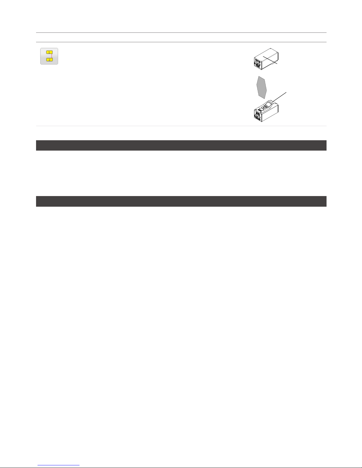
Setup • 71Gocator 2000 & 2300 Series
Orientation Example
Opposite
Sensors are mounted in Top (Main) or Bottom (Buddy) positions for
a larger combined measurement range and the ability to perform
Top/Bottom differential measurements.
Main
Buddy
Overlap
If the Main and Buddy sensors are mounted such that the camera from one sensor can detect the laser
from the other sensor, the Overlap feature can be used to eliminate laser interference. Overlap creates a
time offset for laser exposures and ensures that interfering lasers are not strobed at the same time. Use
of the overlap feature may reduce the maximum frame rate.
Reverse
In the Wide layout, the Buddy sensors can be mounted such that it is rotated 180 degrees around the
z-axis to prevent occlusion along the y-axis. Enable the Reverse feature when the buddy is mounted in
this reverse orientation.

Setup • 72Gocator 2000 & 2300 Series
Calibration
Although Gocator sensors are pre-calibrated and ready to deliver profiles out of the box, calibration
procedures are required to compensate for sensor mounting inaccuracies, to align multiple sensors into
a common coordinate system, and to determine the resolution (with encoder) and speed of the transport
system.
Gocator sensors support two types of calibration procedures: Alignment Calibration and Travel
Calibration. Travel calibration performs essentially the same role as alignment calibration, but calibrates
encoder resolution and y-axis offsets in addition to the corrections provided by alignment calibration.
Once calibration has been completed, the values derived will be saved automatically and reloaded each
time the sensor is reset or powered up.
Calibration States
A Gocator can be in one of three calibration states: None, Manual, or Auto.
Calibration States
State Explanation
None Sensor has no calibration. Ranges are reported in default sensor
coordinates.
Manual User has manually edited transformations or encoder resolution.
Auto Sensor is calibrated using either alignment or travel calibration.
An indicator on the Calibration panel will display CALIBRATED, MANUALLY CALIBRATED or NOT
CALIBRATED.
Alignment vs. Travel Calibration
The table below summarizes the differences between alignment calibration and travel calibration.
Alignment Calibration vs. Travel Calibration
Alignment Calibration Travel Calibration
Target Type Flat Surface or Cal Bar Cal Disk or Cal Bar
Target/Sensor Motion Stationary Linear Motion
Calibrates Tilt Yes Ye s
Calibrates z-axis Offset Yes Yes
Calibrates x-axis Offset Yes (Cal Bar Required) Yes
Calibrates Encoder No Ye s
Calibrates Travel Speed No Yes
Refer to Coordinate Systems (page 52) for definitions of coordinate axes. Calibration disks and bars
are described in Calibration Targets (page 28).
The procedures to perform alignment calibration or travel calibration are described in the next sections.
After calibration, the coordinate system for laser profiles will change from Sensor Coordinates to System
Coordinates.
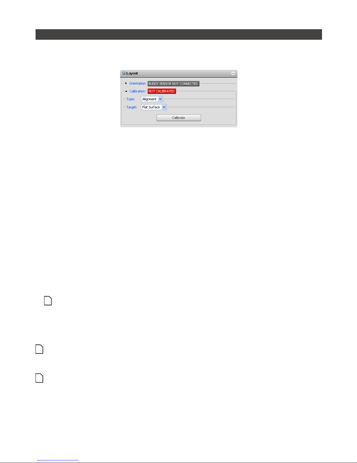
Setup • 73Gocator 2000 & 2300 Series
Alignment Calibration
Alignment calibration can be used to compensate for mounting inaccuracies by aligning sensor data to
a common reference surface (often a conveyor belt).
To perform alignment calibration:
1 Ensure that all sensors have a clear view of the target surface.
Remove any irregular objects from the sensor's field of view that might interfere with alignment calibration.
If using a calibration bar for dual sensor system, ensure that the lasers illuminate a reference hole on the
calibration bar.
2 Navigate to the Layout panel and select Alignment Calibration.
Click the arrow button next to Calibration to expand the panel.
3 Clear the previous calibration if present.
Press the Clear Calibration button to remove the existing calibration.
4 Select a calibration Target.
Select Flat Surface to use the conveyor surface (or other flat surface) as the calibration reference, or Bar
to use a custom calibration bar. If using a calibration bar, specify the bar dimensions and reference hole
layout. Refer to Calibration Targets (page 28) for more information.
5 Press the Calibrate button.
The sensors will start and the alignment calibration process will take place. Calibration is performed
simultaneously for all sensors. If the sensors do not calibrate, check and adjust the exposure settings.
Alignment calibration uses the exposure defined for the single exposure mode, regardless of the
current exposure mode.
6 Use Profile Mode to inspect calibration results.
Laser profiles from all sensors should now be aligned to the calibration target surface. The base of the
calibration target (or target surface) provides the origin for the system z-axis.
Alignment calibration does not automatically calibrate the resolution of the encoder (if present) or the travel
speed. However, the these values can be manually entered if desired. Refer to Trigger (page 55) for more
information.
When using a calibration bar, there can be at most one hole in each sensor's field of view.
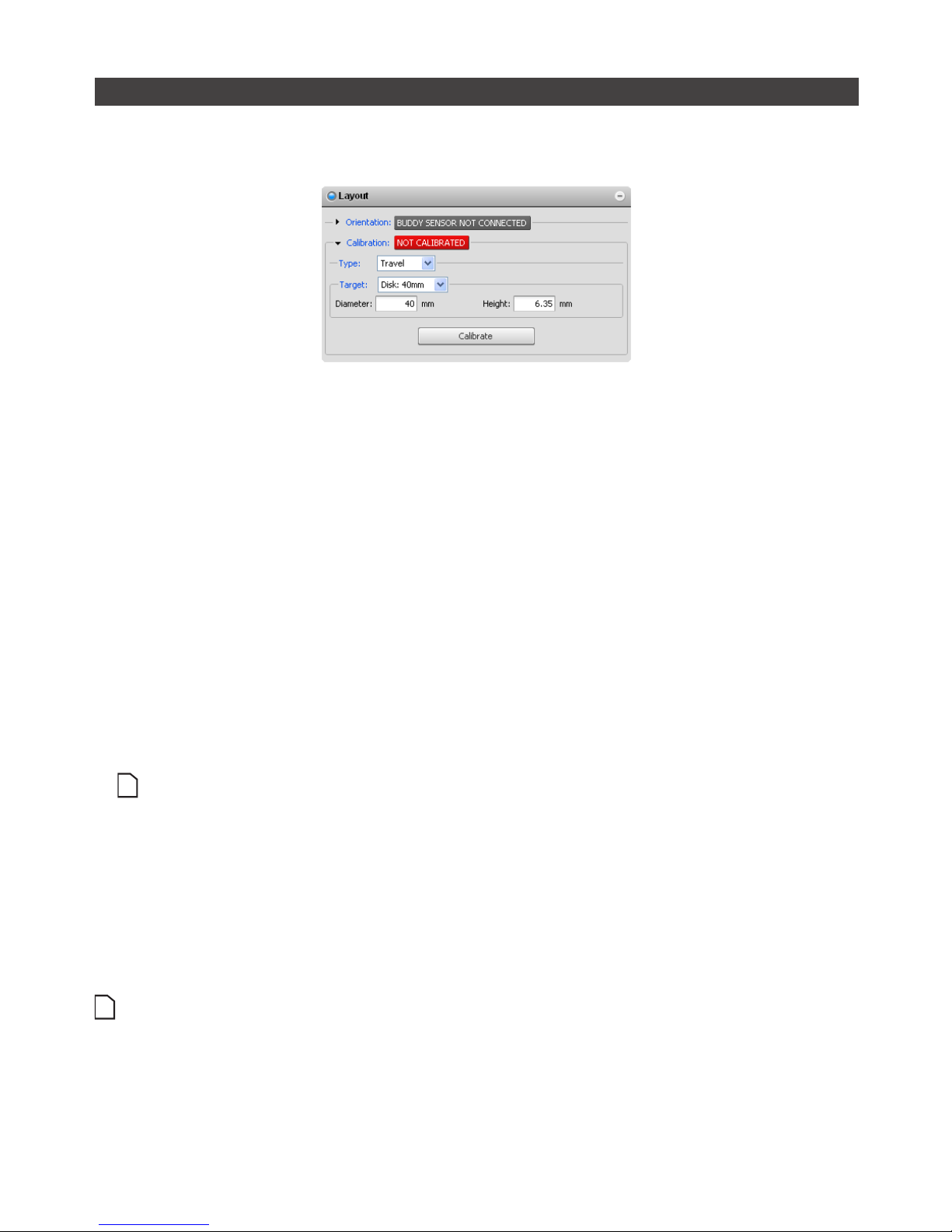
Setup • 74Gocator 2000 & 2300 Series
Travel Calibration
Travel calibration can be used to achieve alignment calibration and motion calibration in a single
procedure.
To perform travel calibration:
1 Place the calibration target prior to the laser plane.
Remove extraneous objects from the transport system such that the calibration target will be the only
object that is scanned.
2 Navigate to the Layout panel and select Travel Calibration.
Click the arrow button next to Calibration to expand the panel.
3 Clear the previous calibration, if present.
Press the Clear Calibration button to remove the existing calibration.
4 Select a calibration Target.
Select one of the Disk options to use a standard disk target or Bar to use a custom-made calibration bar. If
using a calibration bar, specify the bar dimensions and reference hole layout. Refer to Calibration Targets
(page 28) for more information.
5 Press the Calibrate button.
The sensors will start and then wait for the calibration target to pass through the laser plane.
Travel calibration uses the exposure defined for the single exposure mode, regardless of the current
exposure mode.
6 Engage the transport system.
When the calibration target has passed completely through the laser plane, the calibration process will
complete automatically. To properly calibrate the travel speed, the transport system must be running at the
production operating speed before the target passes through the laser plane.
7 Use Profile Mode to inspect calibration results.
Laser profiles from all sensors should now be aligned to the calibration target surface. The base of the
calibration target (or target surface) provides the origin for the system z-axis.
When using a calibration bar, there can be at most one hole in each sensor's field of view. If a disk is used for
calibrating a dual-sensor setup in a wide layout, half of the disk must be in each sensor's field of view.

Setup • 75Gocator 2000 & 2300 Series
Clearing Calibration
To clear calibration:
1 Navigate to the Calibration panel on the Setup page.
2 Click the Calibration or Clear Calibration button.
If the Clear Calibration button is pressed, the calibration will be erased and sensors will revert to using
Sensor Coordinates.

Setup • 76Gocator 2000 & 2300 Series
Filters
The Filters Panel can be used to post process the profile before it is output or is used by measurement
tools. Three types of filters are supported:
Filters Description
X Resampling Interval Configure resampling interval size to balance between CPU loading, output data rate
and x-resolution.
Smoothing Apply moving window averaging to reduce random noise in a profile.
Gap Filling Fill in missing data caused by occlusions using information from the nearest neighbors.
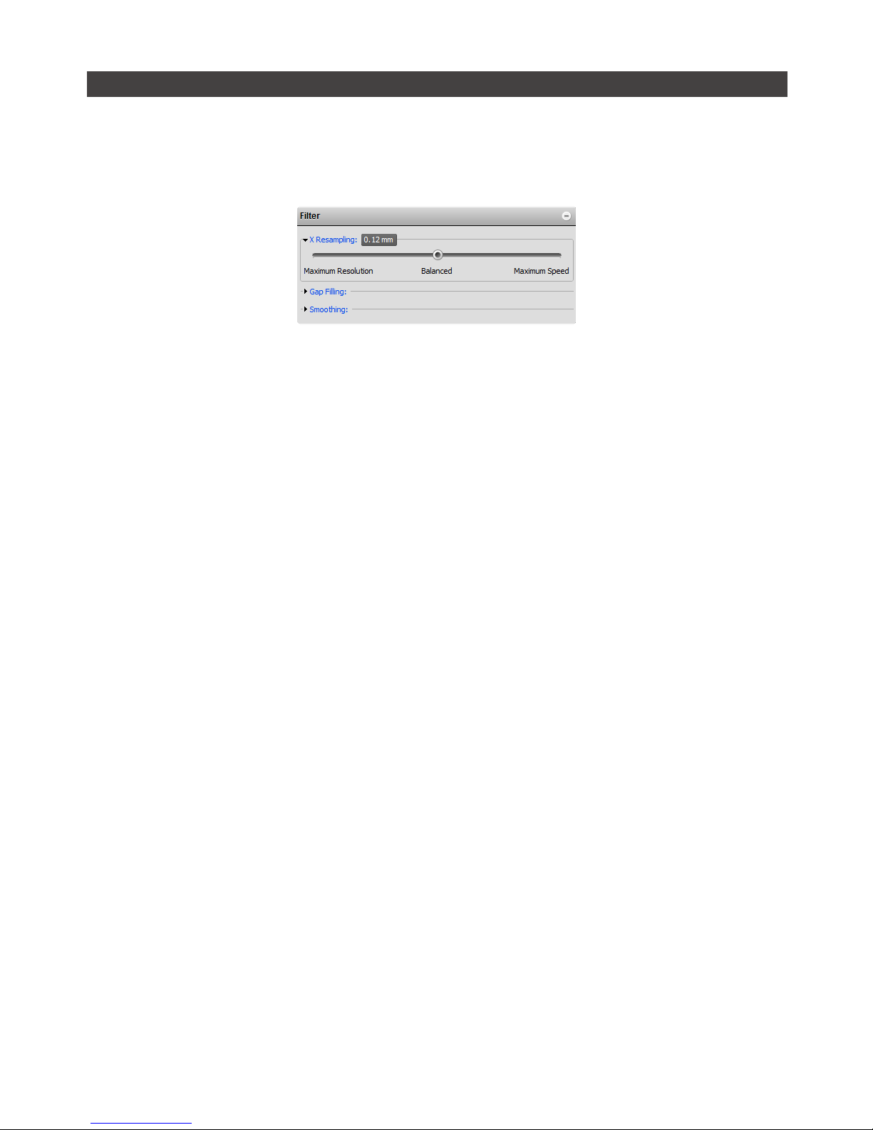
Setup • 77Gocator 2000 & 2300 Series
X Resampling Interval
Resampling interval is the spacing between data points in a resampled profile (page 52). A larger
interval creates profiles with lower x-resolution but reduces CPU usage and potentially increases the
maximum frame rate. A larger interval also reduces the data output rate.
By default, the Gocator output data at the medium resolution.
To configure the X resampling interval:
1 Select the Profile or Part Mode.
2 Navigate to the Filters panel.
Click the arrow next to X Resampling to expand the panel.
3 Select a resampling interval level.
Maximum Speed: Use the lowest x-resolution within the active area as the resampling interval. This setting
minimizes CPU usage and data output rate but the profile has the lowest x-resolution (i.e. least detail)
Balanced: Use the x-resolution at the middle of the active area as the resampling interval. This setting
balances CPU load, data output rate and the x-resolution.
Maximum Resolution: Use the highest x-resolution within the active area as the resampling interval. This
setting maximizes resolution but has higher CPU load and has the highest data output rate. (i.e. greatest
detail).
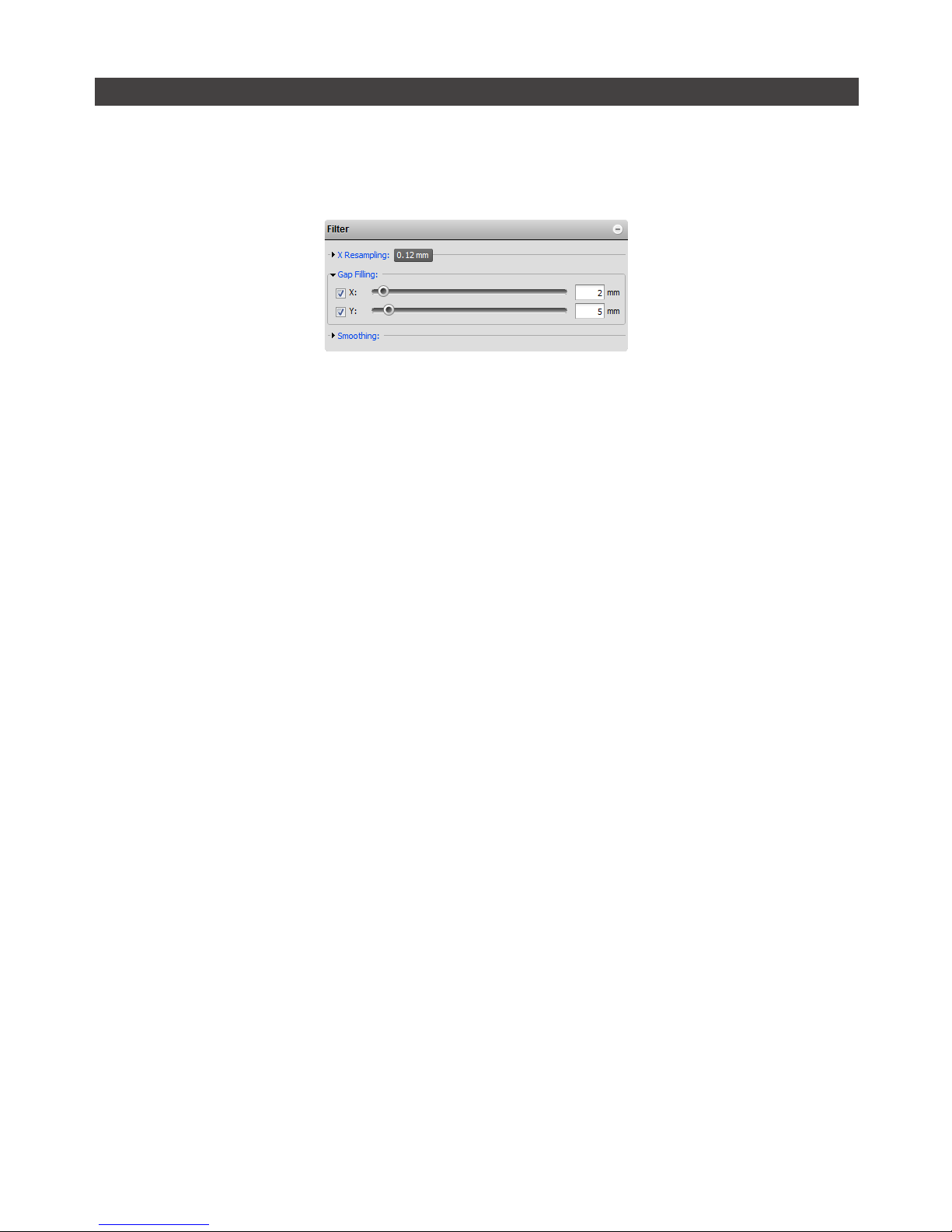
Setup • 78Gocator 2000 & 2300 Series
Gap Filling
Gap filling works by filling in missing data points using the lowest values from the nearest neighbors. The
sensor can fill gaps along both the x-axis and the y-axis. X gap filling works by filling in the gaps within
the same profile. Y gap filling works by filling in gaps in the direction of travel at each x location.
If both X and Y gap filling are enabled, missing data is filled along the x-axis first, then along the y-axis.
To configure X gap filling:
1 Select the Profile or Part Mode.
2 Navigate to the Filters panel.
Click the arrow next to Gap Filling to expand the panel.
3 Enable X gap filling and select the maximum width value.
The maximum gap value represents the maximum gap width that the Gocator will fill. Gaps wider than the
maximum width will not be filled.
4 Check that the laser profiling is satisfactory.
To configure Y gap filling:
1 Select the Profile or Part Mode.
2 Navigate to the Filters panel
Click the arrow next to Gap Filling to expand the panel.
3 Enable Y gap filling and select the maximum width value.
The maximum gap value represents the maximum gap width that the Gocator will fill. Gaps wider than the
maximum width will not be filled.
4 Check that the laser profiling is satisfactory.
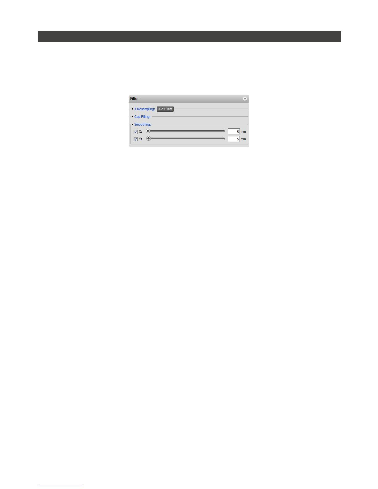
Setup • 79Gocator 2000 & 2300 Series
Smoothing
Smoothing works by substituting a profile result with the average value of itself and its nearest neighbors.
Smoothing can be applied along the x-axis or the y-axis. X smoothing works by calculating a moving
average across samples within the same profile. Y smoothing works by calculating a moving average in
the direction of travel at each x location.
If both X and Y smoothing are enabled, the data is smoothed along x-axis first, then along the y-axis.
To configure X smoothing:
1 Select the Profile or Part Mode.
2 Navigate to the Filters panel.
Click the arrow next to Smoothing to expand the panel.
3 Enable X Smoothing and select the window value.
The window value represents the averaging window size in the x-axis.
4 Check that the laser profiling is satisfactory.
To configure Y smoothing:
1 Select the Profile or Part Mode.
2 Navigate to the Filters panel.
Click the arrow next to Smoothing to expand the panel.
3 Enable Y Smoothing and select the window value.
The window value represents the average window size in the y-axis.
4 Check that the laser profiling is satisfactory.

Setup • 80Gocator 2000 & 2300 Series
Part Detection
In Part Mode, the Gocator sensor analyzes each profile to identify discrete objects. Part measurements
can then be performed on each discrete object.
Part detection can be performed when the trigger source is set to Time or Encoder. To use the Time
trigger source, the travel speed needs to be calibrated. To use the Encoder trigger source, the encoder
resolution needs to be calibrated. Refer to Travel Calibration (page 74) for more information.
Multiple parts can pass through the laser at the same time and will be individually tracked. Parts can be
separated along the laser line (x-axis), in the direction of travel (y-axis) or by gated external input.
The following settings can be tuned to improve the accuracy and reliability of the part detection.
Setting Description
Gap Threshold Determines the minimum separation between objects in the XY plane. If parts are
closer than the gap interval, they will be merged into a single part.
Height Threshold Determines the minimum profile height for part detection. This setting is useful when
measuring objects on a conveyor, to prevent the conveyor from being detected as a
part. Any data points below the height threshold will not be taken into account when
calculating the part measurements
In an opposite layout, the threshold is applied to the difference between the top and
the bottom profile. Target thinner than the threshold value is ignored, including places
where only one of either top or bottom is detected.
To separate part by gated external input, set the Height Threshold to the Active area
Z-offset (i.e. minimum Z position of the current Active Area), set the trigger source to
Time or Encoder and check the Gate Using External Input check box.
Area Threshold Determines the minimum area for a detected part. Set this value to a reasonable
minimum in order to filter out small objects or noise.
Length Max Determines the maximum length of the part object. When the object exceeds the
maximum length, it is automatically separated into two parts. This is useful to break a
long object into multiple sections and perform measurements on each section.
To setup part detection:
1 Navigate to the Operation Mode Panel, select Part Mode.

Setup • 81Gocator 2000 & 2300 Series
2 Navigate to the Part Detection panel.
3 Adjust the settings.
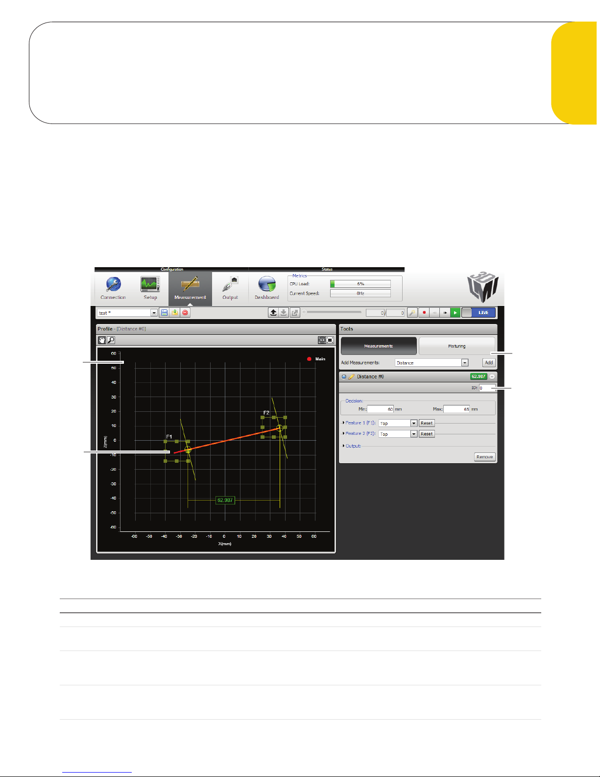
82Gocator 2000 & 2300 Series
Measurement
Measurement Page
Measurement tools are configured using the Measurement Page.
The content of the Measurement Page is controlled by the current operation mode. In Profile Mode,
the Measurement Page displays tools for profile measurement. In Part Mode, the Measurement page
displays tools for part measurement. The Measurement page is disabled in Video and Raw mode.
3
1
2
4
Element Description
1 Tools Panel Use the Tools panel to add new measurements or to configure fixturing.
2 Measurement Panel For each measurement that is added, a configuration area will appear below the
Measurements panel. Use this area to adjust settings for the measurement.
3 Data Viewer Displays laser profile or part data, setup tools and display result calipers related to the
selected measurement. Parts are displayed using a height map; A top-down view of the XY
plane, where color represents height.
4 Feature Area Configurable region of interest from which feature points are detected. These feature points
are used to calculate the measurements. The number of feature area displayed depends on
which measurement tool is currently selected.

Measurement • 83Gocator 2000 & 2300 Series
Adding and Removing Measurements
To add a new profile measurement:
1 Select the desired measurement type.
Click on the item in the drop-down list next to Add Measurement to select the measurement type.
2 Press the Add button.
A configuration panel for the new measurement will be added to the bottom of the stack.
To remove a new profile measurement:
1 Select the desired measurement.
Click on the title bar of the measurement to select it.
2 Click the Remove button.
The measurement will be removed from the list of measurements.
If the Add Measurement list contains only the Distance measurement, then the sensor is not equipped with
profile tools. The Distance measurement is provided in all sensors to demonstrate the measurement capability.

Measurement • 84Gocator 2000 & 2300 Series
Changing the Measurement Name
Each measurement can be assigned a unique name. This allows multiple measurements of the same
type to be distinguished in the web interface. The name is also referenced by the Script tool.
To edit a measurement name:
1 Click on the measurement name.
2 Enter a new name.
3 Press the Tab key.
The name change will be completed when you press the Tab Key or click outside of the name edit field.

Measurement • 85Gocator 2000 & 2300 Series
Measurement ID
Measurement ID is used to uniquely identify a measurement in the Gocator protocol or in the SDK. The
value must be unique amongst all profile and part measurements.
To edit a measurement ID:
1 Select a measurement.
Click on the + in a measurement panel to expand the panel.
2 Click on the measurement ID.
3 Enter a new number.
The value must be unique amongst all measurements in Profile and Part Mode.
4 Press the Tab key.
The name change will be completed when you press the Tab Key or click outside of the measurement ID
edit field.

Measurement • 86Gocator 2000 & 2300 Series
Profile Sources
For dual sensor systems, measurements must specify a profile source. The profile source determines the
data that will be used for the measurement.
The following options are available:
Profile Source Description
Main Profile data is provided by the Main sensor. This is the only option for standalone
systems.
Buddy Profile data is provided by the Buddy sensor.
Both Profile data is provided by the Main and the Buddy sensor.
To select the profile source:
1 Select a measurement.
Click on the + in a measurement panel to expand it.
2 Select the profile Source.
Select the source in the drop down list. The drop down list will not appear if Main is the only option.

Measurement • 87Gocator 2000 & 2300 Series
Decisions
Results from a measurement tool can be compared against minimum and maximum thresholds to
generate pass / fail decisions. The decision state is pass (value displayed in green) if a measurement
value is between the minimum and maximum threshold, otherwise the decision state is fail (value
displayed in red).
Value (50.380) is within the decision thresholds (Min: 80, Max:100). Decision: Pass
Value (51.216) is outside decision thresholds (Min:80, Max:100)
Decision: Fail
Value (51.216) is outside the decision thresholds (Min: 80, Max: 100). Decision: Fail
Along with measurement values, decisions can be sent to external programs and devices. In particular,
decisions are often used in conjunction with digital outputs to trigger an external event in response to a
measurement. Refer to Output (page 182) for more information on transmitting values and decisions.
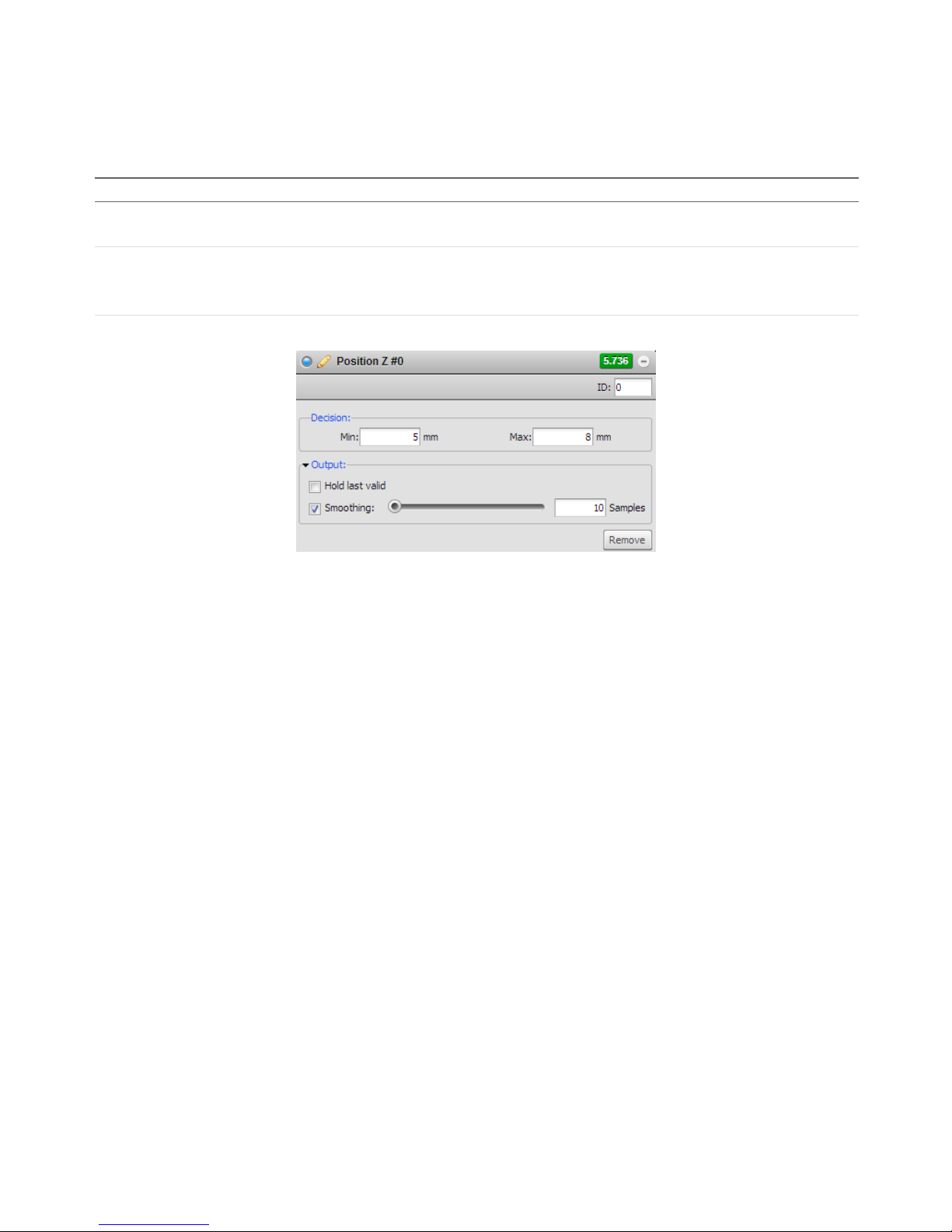
Measurement • 88Gocator 2000 & 2300 Series
Output Filters
Filters can be applied to measurement values before they are output from the Gocator sensors. Two
filters are supported.
Operation Description
Hold Last Valid Hold the last valid value when the measurement is invalid. Measurement is invalid if
there is no valid value.
Smoothing Apply moving window averaging to reduce random noise in a measurement output.
The averaging window is configured in number of frames.
If Hold Last Valid is enabled, smoothing uses the output of the Hold Last Valid filter.
To configure the output filters:
1 Select a measurement.
Click on the + in a measurement panel to expand it. Click the arrow next to Output to expand the panel.
2 Enable filters and configure the settings.

Measurement • 89Gocator 2000 & 2300 Series
Profile Fixturing
Profile fixturing is used to track the movement of parts along the laser line (x-axis and z-axis). The
movement is calculated as an offset and is used to correct the positions of the feature areas. This
ensures that the regions-of-interest used to detect features are correctly positioned for every part.
Profile fixturing is not required in order to use measurement functions. This is an optional feature
intended to make measurements more robust when the x-position and the height of the target varies
from target to target.
A profile template is needed for fixturing to function. The profile template is the reference used to
calculate the profile movement in the x-axis and z-axis. User defines a detection area (white rectangles
in the picture above) and the type of feature point to detect within the area. When the profile template
and the live profile falls into the area, the movement is calculated by computing the difference between
the positions of the feature point of the profile template and the live profile.
To register a profile template:
1 Position a representative target object within the field of view.
The target should be similar to the objects that will later be measured. The Start or Snapshot buttons can
be used to view live profile data while positioning the target.
2 Click the Register button.
A snapshot of the target object will be captured and set as the current profile template. The profile
template is shown in white within the Data Viewer.
After a profile is registered, fixturing in the x-axis and z-axis can be configured independently.

Measurement • 90Gocator 2000 & 2300 Series
To set up profile fixturing in the x-axis:
1 Press the Fixturing button in the Measurement panel.
2 Enable X Fixturing
Check the X-Fixturing box to enable fixturing in the x-axis.
3 Adjust the detection area.
Profile data within the detection area will be used to calculate the feature point for fixturing.
4 Select an feature point type.
Select the feature point type from the Detect drop-down box. The point type determines how the feature
point is calculated from the profile data within the detection area.
To set up profile fixturing in the z-axis with a new template:
1 Press the Fixturing button in the Measurement panel.
2 Enable Z Fixturing.
Check the Z Fixturing box to enable fixturing in the z-axis.
3 Adjust the detection area.
Profile data within the detection area will be used to calculate the feature point for fixturing.
4 Select an feature point type.
Select the feature point type from the Detect drop-down box. The point type determines how the feature
point is calculated from the profile data within the detection area.
When profile fixturing is used, the measurement's areas should be setup to match with the profile
template. The profile template is hidden when the sensor is running. When the sensor is stopped and the
user is viewing the measurement page, the profile template will be automatically reloaded in the Data
Viewer.
To clear a registered profile template:
1 Press the Fixturing button in the Measurements panel.
2 Click the Clear button.
Changes to profile fixturing and the template are temporary until they are saved. Refer to Saving and
Loading Settings (page 194) for more details on how to save changes.

Measurement • 91Gocator 2000 & 2300 Series
Script Measurement
A Script measurement can be used to program a custom measurement using a simplified C-based
syntax. Similar to other measurement tools, a script measurement can produce a measurement value
and a measurement decision.
The following elements of the C language are supported:
Supported Elements
Elements Supported
Control Operators
if, while, do, for, switch and return.
Data Types char, int, unsigned int, float, double, long long (64-bit integer).
Arithmetic and Logical
Operator
Standard C arithmetic operators, except ternary operator (i.e. “condition? trueValue:
falseValue”). Explicit casting (e.g. int a = (int) a_float) is not supported.
Function Declarations Standard C function declarations with argument passed by values. Pointers are not
supported.
Built-in Functions
Measurement Functions
Measurement Functions Descriptions
int Measurement_Exists(int id) Tests for the existence of a measurement by ID.
Parameters:
id – Measurement ID
Returns:
0 – measurement does not exist
1 – measurement exists
int Measurement_Valid(int id) Retrieves the valid/invalid state of a measurement by its ID.
Parameters:
id - Measurement ID
Returns
0 - Measurement is invalid
1 - Measurement is valid
long long Measurement_Value (int id) Retrieves the value of a measurement by its ID.
Parameters:
id - Measurement ID
Returns:
Value of the measurement
0 – if measurement does not exist
A measurement value is received as a fixed point integer with a scaling of
1/1000. For example, a 3.654mm value is received as 3654.
int Measurement_Decision (int id) Retrieves the decision of a measurement by its ID.
Parameters:
ID - Measurement ID
Returns:
Decision of the measurement
0 – if measurement decision is false
1 – If measurement decision is true

Measurement • 92Gocator 2000 & 2300 Series
int Measurement_NameExists(char *name) Determines if a measurement exist by name.
Parameter:
name – name of a measurement
Return:
0 – measurement does not exist
1 – measurement exists
int Measurement_Id (char *name) Retrieves the measurement ID by the measurement name.
Parameters:
name – name of a measurement
Returns:
-1 – measurement does not exist
Other – Measurement ID
void Output_Set (long long value, int
decision)
Output a value and decision. Only the last output value / decision in a script
run is kept and passed to the Gocator output.
Parameters:
value - value output by the script
decision - decision value output by the script. Can only be 0 or 1
Memory Functions
Memory Functions Descriptions
void Memory_Set64s (int id, long long value) Stores a 64-bit signed integer in persistent memory.
Parameters:
id - ID of the value
value - Value to store
long long Memory_Get64s (int id) Retrieves a 64-bit signed integer from persistent memory.
Parameters:
id - ID of the value
Returns:
value - Value stored in persistent memory
void Memory_Set64u (int id, unsigned long
long value)
Stores a 64-bit unsigned integer in the persistent memory
Parameters:
id - ID of the value
value - Value to store
unsigned long long Memory_Get64u (int id) Retrieves a 64-bit unsigned integer from persistent memory.
Parameters:
id - ID of the value
Returns:
value - Value stored in persistent memory
void Memory_Set64f (int id, double value) Stores a 64-bit double into persistent memory.
Parameters:
id - ID of the value
value - Value to store
double Memory_Get64f (int id) Retrieves a 64-bit double from persistent memory. All persistent memory
values are set to 0 when the sensor starts.
Parameters:
id - ID of the value
Returns:
value - Value stored in persistent memory

Measurement • 93Gocator 2000 & 2300 Series
int Memory_Exists (int id) Tests for the existence of a value by ID.
Parameters:
id – Value ID
Returns:
0 – value does not exist
1 – value exists
void Memory_Clear (int id) Erases a value associated with a ID.
Parameters:
id – Value ID
void Memory_ClearAll() Erases all value from persistent memory
Stamp Functions
Stamp Functions Descriptions
long long Stamp_Frame() Retrieves the frame index of the current frame.
long long Stamp_Time() Retrieves the time stamp of the current frame.
long long Stamp_Encoder() Retrieves the encoder position of the current frame.
long long Stamp_EncoderZ() Retrieves the encoder index position of the current frame.
unsigned int Stamp_Inputs() Retrieves the digital input state of the current frame.
Math Functions
Math Functions Descriptions
float sqrt(float x) Calculates square root of x
float sin(float x) Calculates sin(x) (x in radians)
float cos(float x) Calculates cos(x) (x in radians)
float tan(float x) Calculates tan(x) (x in radians)
float asin(float x) Calculates asin(x) (x in radians)
float acos(float x) Calculates acos(x) (x in radians)
float atan(float x) Calculates atan(x) (x in radians)
float pow (float x, float y) Calculates the exponential value. x is the base, y is the exponent
float fabs(float x) Calculates the absolute value of x

Measurement • 94Gocator 2000 & 2300 Series
Example: Accumulated Volume
The following example demonstrates how to create a custom measurement that is based on the values
from other measurements and persistent values. The example calculates the volume of the target using
a series of box area measurement values.
/* Calculate the volume of an object by accumulating the boxArea measurements*/
/* Encoder Resolution is 0.5mm. */
/* BoxArea Measurement ID is set to 1*/
long long encoder_res = 500;
long long boxArea = Measurement_Value(1);
long long Volume = Memory_Get64s(0);
if (boxArea > 0)
{
Volume = Volume + (boxArea/1000) * encoder_res;
}
Memory_Set64s(0, Volume);
if (Volume > 1000000)
{
Output_Set(Volume, 1);
}
else
{
Output_Set(Volume, 0);
}
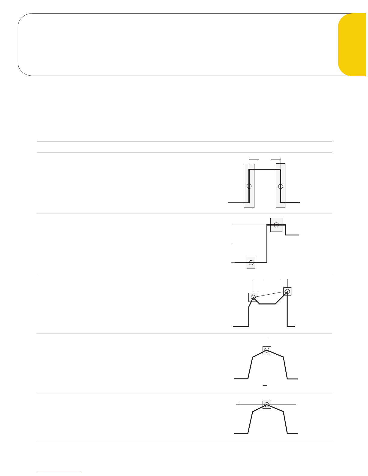
95Gocator 2000 & 2300 Series
This chapter describes the profile measurement tools available in sensors that are equipped with
Measurement Tools.
Most measurement functions detect and compare feature points or lines found within laser profile data.
Measurement values are compared against minimum and maximum thresholds to yield decisions.
Measurement Examples
Width
Measures the difference in the x-axis position of two feature
points.
Refer to Width (page 105).
Width
Height
Measures the difference in the z-axis position of two
features.
Refer to Height (page 106).
Height
Distance
Measures the Euclidean distance between two features.
Refer to Distance (page 107).
Distance
Position X
Finds the x-axis position of a feature.
Refer to Position X (page 108).
Position X
Position Z
Finds the z-axis position of a feature.
Refer to Position Z (page 109).
Position Z
Profile Measurement Tools
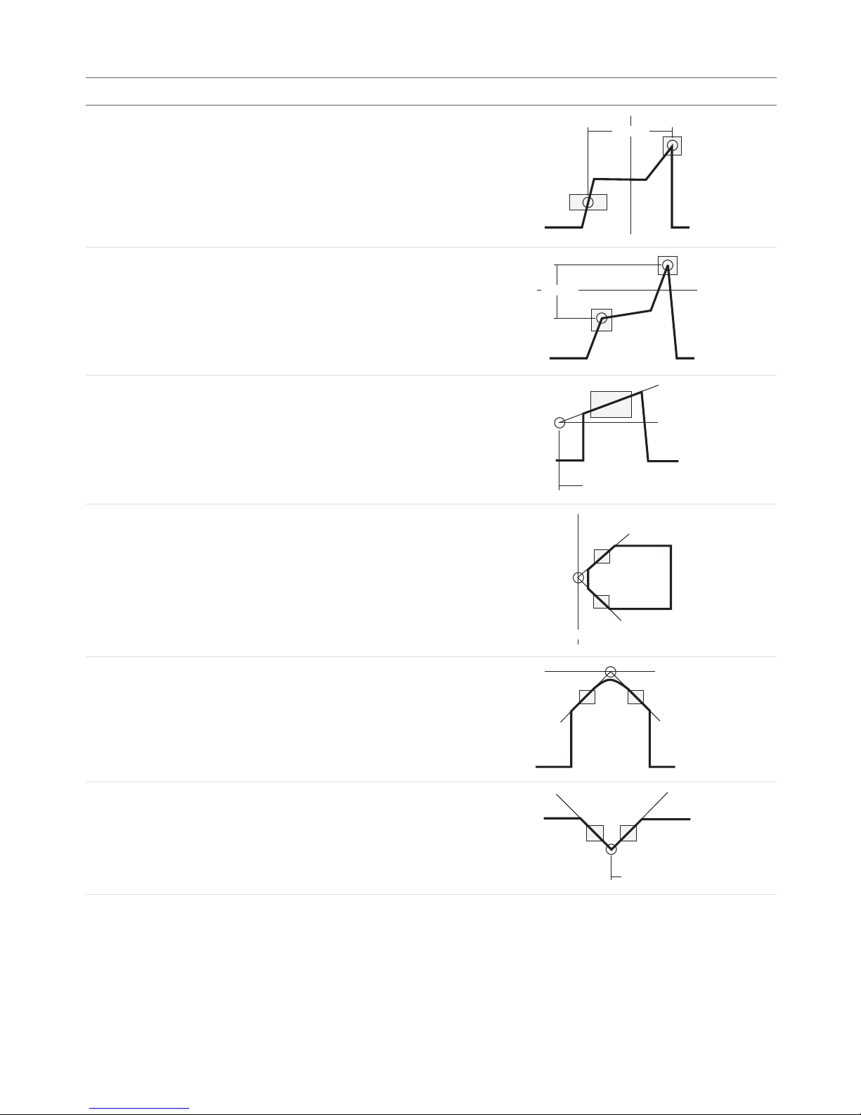
Measurement • 96Gocator 2000 & 2300 Series
Measurement Examples
Center X
Finds the average location of two features and measures the
x-axis position of the average location.
Refer to Center X (page 110).
Center X
Center Z
Finds the average location of two features and measures the
z-axis position of the average location.
Refer to Center Z (page 111).
Center Z
Angle X
Fits a line to profile points within one or two areas and
measures the angle between the fitted line and the x-axis.
Refer to Angle X (page 112).
Angle X
Intersect X
Finds the intersection between two fitted lines and measures
the x-axis position of the intersection point.
Refer to Intersect X (page 113).
Intersect X
Intersect Z
Finds the intersection between two fitted lines and measures
the z-axis position of the intersection point.
Refer to Intersect Z (page 114).
Intersect Z
Intersect Angle
Finds the angle subtended by two fitted lines.
Refer to Intersect Angle (page 115).
Intersect Angle

Measurement • 97Gocator 2000 & 2300 Series
Measurement Examples
Intersect Area
Measures the cross-sectional area within a region that is
above or below a fitted baseline.
Refer to Intersect Area (page 116).
Intersect Area
[Object]
Intersect Area
[Clearance]
Box Area
Measures the cross-sectional area within a region.
Refer to Box Area (page 117).
Box Area
Difference Area
Measures the difference in cross-sectional area between live
profile and the template.
Refer to Difference Area (page 118).
Difference Area
Live Profile
Template
Difference Peak
Measures the maximum difference in height between the live
profile and the template.
Refer to Difference Peak (page 119).
Difference Peak
Circle Radius
Finds the best-fitted circle and measures the circle radius.
Refer to Circle Radius (page 120).
Radius
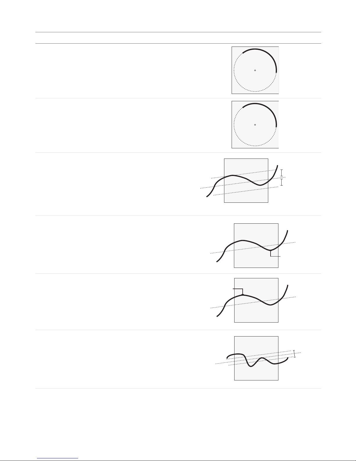
Measurement • 98Gocator 2000 & 2300 Series
Measurement Examples
Circle X
Finds the best-fitted circle and measures the circle center
position in the x-axis.
Refer to Circle X (page 121).
Center
(X, Z)
Circle Z
Finds the best-fitted circle and measures the circle center
position in the z-axis.
Refer to Circle Z (page 122).
Center
(X, Z)
Line Standard Deviation
Finds the best-fitted line and measures the standard
deviation of the laser points from the best-fitted line.
Refer to Line Standard Deviation (page 123).
Standard Deviation
Standard Deviation
Line Error Min
Finds the best-fitted line and measures the minimum error
from the best-fitted line.
Refer to Line Error Min (page 124).
Line Error Min.
Line Error Max
Find the best-fitted line and measures the maximum error
from the best-fitted line.
Refer to Line Error Max (page 125).
Line Error Max.
Line Percentile
Finds the best-fitted line and measures the range (in z) that
covers a percentage of points around the best-fitted line.
Refer to Line Percentile (page 126)
Covers % of Spots
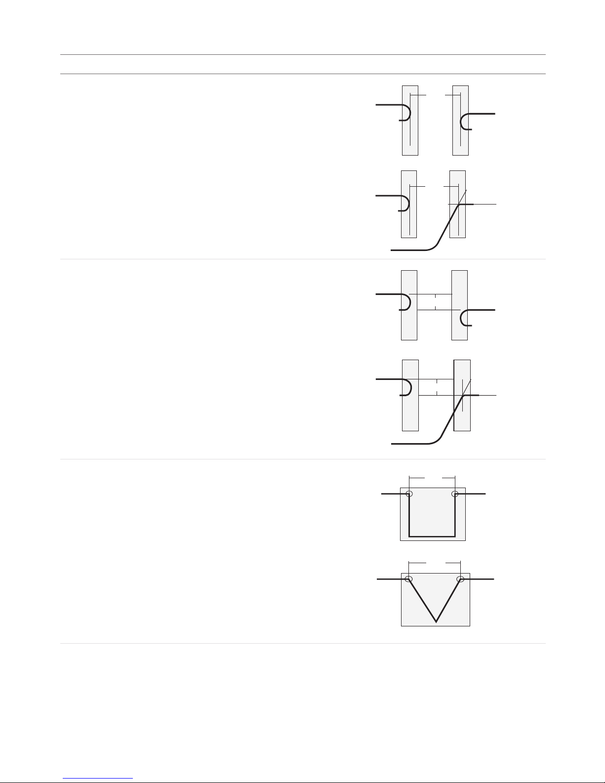
Measurement • 99Gocator 2000 & 2300 Series
Measurement Examples
Gap
Measures the distance between two surfaces. The surface
edges can be curved or sharp.
Refer to Gap (page 127)
Gap
Gap
Flush
Measures the flatness between two surfaces. The surface
edges can be curved or sharp.
Refer to Flush (page 132)
Flush
Flush
Groove Width
Measures the width of a groove.
Refer to Groove Width (page 138)
Width
Width

Measurement • 100Gocator 2000 & 2300 Series
Measurement Examples
Groove X
Measures the x-position of the bottom of a groove.
Refer to Groove X (page 140)
(X, Z)
(X, Z)
Groove Z
Measures the z-position of the bottom of a groove.
Refer to Groove Z (page 142)
(X, Z)
(X, Z)
Strip Width
Measures the width of a strip.
Refer to Strip Width (page 146)
Width
Strip Height
Measures the height of a strip.
Refer to Strip Height (page 149)
Height
Height
Height
Height
Height
Height
Height
 Loading...