

LMI Liquitron DC4500 Series Instruction Manual

InstructionInstruction
sales@novatech-usa.com
www.novatech-usa.com
Tel: (866) 433-6682 Fax: (866) 433-6684
Tel: (281) 359-8538 Fax: (281) 359-0084
Instruction
InstructionInstruction
Liquitron™ DC4500 Series
ManualManual
Manual
ManualManual
For file reference, please record the following data:
Model No:
Serial No:
Installation Date:
Installation Location:
When ordering replacement parts for your LMI Controller or accessory, please include
the complete Model Number and Serial Number of your unit.
Replaces same of Rev. C 7/97
1780.D 7/00

Contents
(866) 433-6682 • (281) 359-8538 • sales@novatech-usa.com • www.novatech-usa.com
1.0 Introduction ........................................................................................................................... 4
2.0 Installation .............................................................................................................................. 6
2.1 Mounting the Controller Enclosure ........................................................................ 6
2.2 Enclosure Mounting Dimensions ........................................................................... 7
2.3 Electrical Wiring Information ................................................................................... 8
2.4 Terminal Strip Layout .............................................................................................. 9
3.0 Operating the Controller ...................................................................................................... 13
3.1 Menu Overview ..................................................................................................... 14
3.2 Conductivity .......................................................................................................... 15
3.3 Set Point ................................................................................................................ 16
3.4 ∆ Differential .......................................................................................................... 17
3.5 Low Alarm ............................................................................................................. 18
3.6 High Alarm ............................................................................................................ 19
3.7 Feed ...................................................................................................................... 20
3.8 Clock ..................................................................................................................... 21
3.9 View Biocide.......................................................................................................... 22
3.10 Add Biocide .......................................................................................................... 23
3.11 Biocide Lockout .................................................................................................... 24
3.12 Biocide Prebleed .................................................................................................. 25
3.13 Manual Outputs .................................................................................................... 26
3.14 Advanced Setup ................................................................................................... 27
3.15 Temperature ......................................................................................................... 28
3.16 H
O Meter ............................................................................................................. 29
2
4.0 Start-Up .............................................................................................................................. 30
4.1 Cooling Tower Installation .................................................................................... 30
4.2 Cooling Tower Start-Up ........................................................................................ 31
4.3 Bleed Sampling Option ........................................................................................ 34
5.0 Calibration ............................................................................................................................ 35
6.0 Maintenance ........................................................................................................................ 36
7.0 Troubleshooting................................................................................................................... 37
8.0 Factory Settings ................................................................................................................... 38
9.0 Product Specifications ......................................................................................................... 39
10.0 Product Exploded View .......................................................................................................40
11.0 Product Parts List ................................................................................................................ 41
3

1.0 Introduction
(866) 433-6682 • (281) 359-8538 • sales@novatech-usa.com • www.novatech-usa.com
The DC4500 is a microprocessor-based conductivity controller. It is designed for use in a variety of water
treatment applications requiring precise control of totally dissolved solids and chemical feed. Among its many
uses, the DC4500 will control conductivity and chemical feed in cooling towers and closed loop systems.
LMI’s DC4500 Series of conductivity controllers allows the greatest programming flexibility for cooling tower
system applications. This is accomplished through the use of an extensive options menu that is easy to use.
BLEED or BLOWDOWN of system water by valve control can be based on several setpoint options:
• Conductivity setpoint
• Hysteresis delay (lower than setpoint) to avoid valve operation chattering
• Rising or Falling conductivity trip points
FEED of chemical (inhibitor) can be based on four (4) different methods and the pump control can be either
On/Off or externally-triggered Variable Speed.
• FEED at the same time system BLEEDS (lockout timer limits maximum FEED time)
• FEED time calculated as a percentage of total BLEED time
• FEED based on a timed cycle (pump is on for a percentage of this timed cycle)
• FEED based on flow meter input
DUAL BIOCIDE chemical addition may be accomplished by the use of two (2) individually programmable
relays or optocoupler outputs. These outputs provide control of two individual chemical addition pumps based
on the following options:
• On/Off or externally-triggered Variable Speed pump control or BOTH for two pump/TIMER operation
• 28-DAY programmable timer (1, 2, 3, or 4 week selectable cycle)
ALARM indicators and relay outputs are energized based on the following conditions:
• HIGH conductivity set point is reached
• LOW conductivity se tpoint is reached
• NO FLOW condition exists (flow switch must be installed)
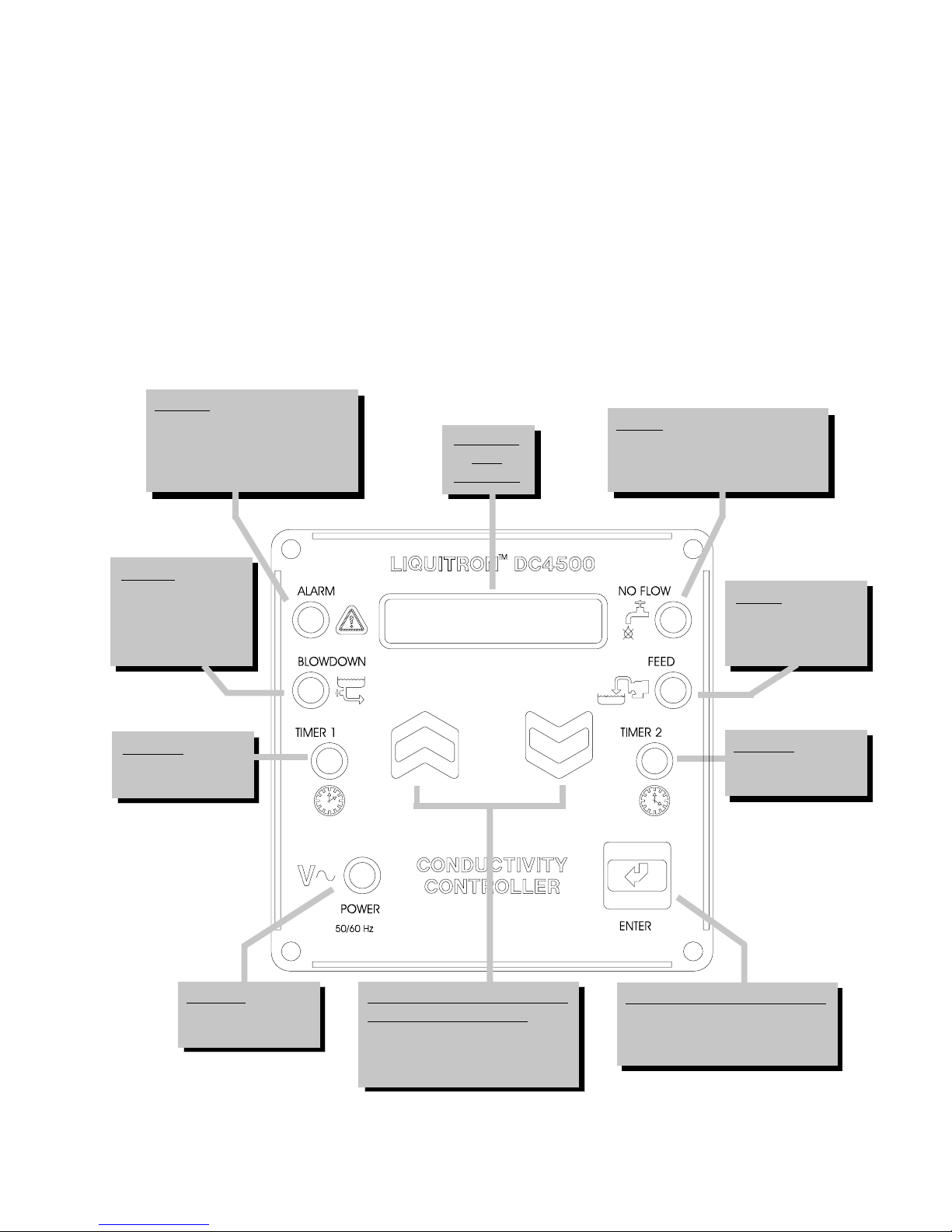
The display is a 16-character backlit LCD (liquid crystal display) which is visible in all light conditions.
A three-key position membrane is used to enter data and settings (see Figure 1).
The conductivity range is 0 - 20,000 µSiemens. The units can be either µSiemens or PPM/TDS (total disolved
solids).
4
All setpoints and parameter settings are retained permanently in a special nonvolatile computer chip memory,
(866) 433-6682 • (281) 359-8538 • sales@novatech-usa.com • www.novatech-usa.com
preventing their loss due to a power outage. This nonvolatile memory chip allows the unit to be programmed
before installation. No battery powered backup is required.
Built in test circuits are provided to test each individual relay output wiring and to allow for quick field
service isolation of faulty probe, circuit cards, pumps, or solenoids for ease of troubleshooting.
A display for temperature is also provided. The range is 32° F to 158° F [0° C to 68° C]. The display can be
either fahrenheit or centigrade. This reading also provides the basis for temperature compensation which is
performed in all modes.
ALARMALARM
ALARM indicator lights when
ALARMALARM
a warning condition occurs:
* high alarm set point
* low alarm set point
* loss of flow
BACKLITBACKLIT
BACKLIT
BACKLITBACKLIT
LCDLCD
LCD
LCDLCD
DISPLAYDISPLAY
DISPLAY
DISPLAYDISPLAY
FLOWFLOW
FLOW indicator lights when
FLOWFLOW
there is a loss of system flow.
Operates only if flow switch is
installed
BLEEDBLEED
BLEED indicator
BLEEDBLEED
lights when the
BLEED OFF or
BLOWNDOWN
output is energized
TIMER 1TIMER 1
TIMER 1 indicator
TIMER 1TIMER 1
lights when timer 1
output is energized
POWERPOWER
POWER indicator
POWERPOWER
lights when power
is supplied to unit
PUSH BUTTON UP ANDPUSH BUTTON UP AND
PUSH BUTTON UP AND
PUSH BUTTON UP ANDPUSH BUTTON UP AND
DOWN ARROW KEYSDOWN ARROW KEYS
DOWN ARROW KEYS allow
DOWN ARROW KEYSDOWN ARROW KEYS
scrolling through menu and
selection or changing of set
point values
FEEDFEED
FEED indicator
FEEDFEED
lights when feed
(inhibitor) output is
energized
TIMER 2TIMER 2
TIMER 2 indicator
TIMER 2TIMER 2
lights when timer 2
output is energized
PUSH BUTTON ENTER KEYPUSH BUTTON ENTER KEY
PUSH BUTTON ENTER KEY
PUSH BUTTON ENTER KEYPUSH BUTTON ENTER KEY
provides for menu selection
and/or acceptance of selected
values
Figure 1Figure 1
Figure 1
Figure 1Figure 1
5

An analog data (or control) output is provided. This is a non-isolated 4 - 20 mA signal. The conductivity
(866) 433-6682 • (281) 359-8538 • sales@novatech-usa.com • www.novatech-usa.com
reading that corresponds to minimum and maximum analog signals is fully adjustable. This signal can be used
to power chart recorders or other pumps and devices.
The controller operates in two (2) distinct modes, ‘SYSTEM RUN’ and ‘SYSTEM START-UP’ or 'PROGRAMMING MODE'. The unit will be in the ‘SYSTEM RUN’ mode when it is first turned on. The various
program screen menus are used to calibrate the unit, set the control and alarm points, set the inhibitor feed
operating parameters, program the biocide [two (2) chemical addition] pumps, and manually test the relays
and wiring connections.
In the ‘SYSTEM RUN’ mode the DC4500 monitors the conductivity and activates the appropriate control or
alarm relay as necessary based on the set points entered in the ‘SYSTEM START-UP’ mode.
The DC4500 is packaged in a NEMA 12X, flame-retardant, molded TPE enclosure. When ordered, 115 VAC
units come fully wired to include input power cord and relay output pigtails to allow for simple installation.
The unit can be hardwired through conduit to the lower junction box portion of the enclosure when required.
Hard wiring makes the unit suitable for NEMA 4X applications.
2.0 Installation
2.1 Mounting the Controller Enclosure
The DC4500 conductivity controller is supplied with integral wall-mounting flanges. It should be mounted
with the display at eye level on a vibration free surface. All accessible mounting holes should be utilized. The
maximum allowable temperature is 122° F [50° C]. This should be considered if installation is in a hightemperature location. Once the DC4500 is wall mounted, the metering pumps may be located at any distance
from the controller. The conductivity probe should be placed as close to the controller as possible, to a
maximum distance of 300 ft [91 m]. Under 25 ft [7.6 m] is recommended. Over 25 ft [7.6 m], the cable may
need to be isolated or shielded from background electrical noise.
6
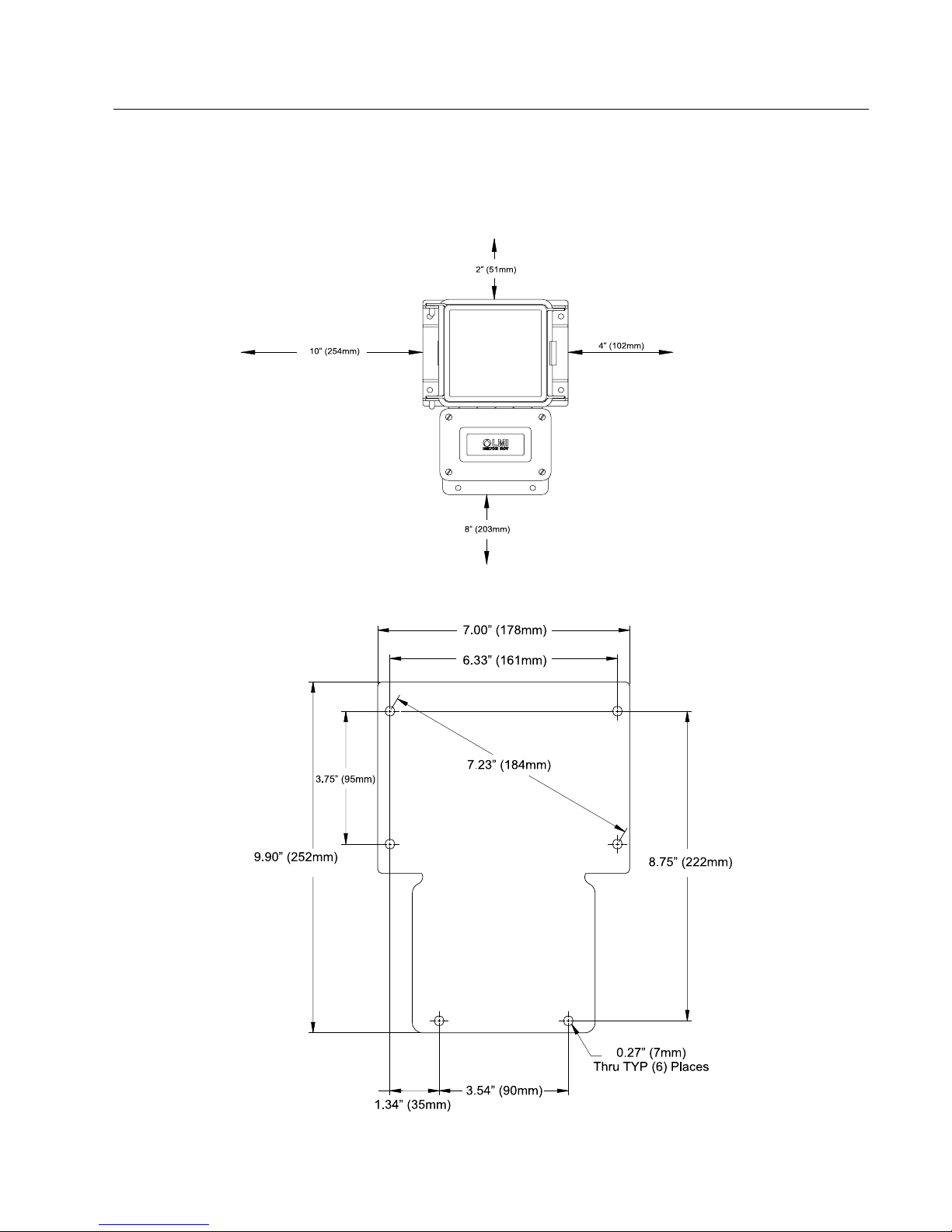
2.2 Enclosure Mounting Dimensions
(866) 433-6682 • (281) 359-8538 • sales@novatech-usa.com • www.novatech-usa.com
When using the prewired unit, the enclosure is configured as NEMA 12X. If the unit is connected through
watertight conduit, the enclosure is configured as NEMA 4X.
The following clearances should be observed for proper mounting (see Figures 2 and 3).
Figure 2Figure 2
Figure 2
Figure 2Figure 2
Figure 3Figure 3
Figure 3
Figure 3Figure 3
7

2.3 Electrical Wiring Information
(866) 433-6682 • (281) 359-8538 • sales@novatech-usa.com • www.novatech-usa.com
To reduce the risk of electrical shock, the controller must be plugged into a grounded outlet with ratings
conforming to the specifications on the data nameplate. It must be connected to a viable ground circuit. DO
NOT USE ADAPTERS (see Figure 4)! All wiring must conform to required electrical codes.
Figure 4Figure 4
Figure 4
Figure 4Figure 4
The DC4500 conductivity controller is available in either 115 or 230 VAC 50/60 Hz. The 115 VAC version
is supplied with one (1) 6-foot grounded AC power cord and four (4) 12-inch output pigtails for plug-in connection of controlled devices.
A four-pin connector is provided for the conductivity probe and temperature compensation probe.
The DC4500 controller is provided with a voltage selector switch to allow the unit to be used with a 115 VAC
or 230 VAC power source. To change the voltage selection, disconnect the unit from the power source and
remove the front keypad panel. The selector switch is located on the circuit board attached to the back panel.
When switching voltages ensure that power cord and pigtails are appropriately changed.
8

2.4 Terminal Strip Layout
(866) 433-6682 • (281) 359-8538 • sales@novatech-usa.com • www.novatech-usa.com
To access the wiring connections inside of the conductivity controller:
1. Disconnect the unit from electrical power.
2. Remove the four (4) screws and the junction box cover on the lower half of the unit.
3. Consult the specific instructions below for the connections required.
AC Power InputAC Power Input
AC Power Input
AC Power InputAC Power Input
Hot: TB2-1
Neutral: TB1-4
Ground: TB4-4
Bleed Blowdown Control Relay OutputBleed Blowdown Control Relay Output
Bleed Blowdown Control Relay Output
Bleed Blowdown Control Relay OutputBleed Blowdown Control Relay Output
Hot (N.O.): TB5-1
Hot (N.C.): TB5-2
Neutral: TB1-3
Feed OutputFeed Output
Feed Output
Feed OutputFeed Output
Alarm OutputAlarm Output
Alarm Output
Alarm OutputAlarm Output
Ground: TB4-3
On/Off
Hot: TB6-1
Neutral: TB1-2
Ground: TB4-2
External Trigger
High: TB9-3
Low: TB9-4
Hot: TB6-2
Neutral: TB1-1
Ground: TB4-1
9

4 - 20 mAmp Output4 - 20 mAmp Output
(866) 433-6682 • (281) 359-8538 • sales@novatech-usa.com • www.novatech-usa.com
4 - 20 mAmp Output
4 - 20 mAmp Output4 - 20 mAmp Output
( + ) TB9-1
( - ) TB9-2
Biocide #1 Pump OutputBiocide #1 Pump Output
Biocide #1 Pump Output
Biocide #1 Pump OutputBiocide #1 Pump Output
On/Off
Hot: TB6-3
Neutral:TB2-4
Ground: TB3-4
External Trigger
High: TB8-1
Low: TB8-2
Biocide #2 Pump OutputBiocide #2 Pump Output
Biocide #2 Pump Output
Biocide #2 Pump OutputBiocide #2 Pump Output
On/Off
Hot: TB6-4
Neutral:TB2-3
Ground: TB3-3
External Trigger
High: TB8-3
Low: TB8-4
Flowmeter InputFlowmeter Input
Flowmeter Input
Flowmeter InputFlowmeter Input
The inputs are reversible when the flowmeter connection is a relay and has no
polarity
TB10-1
TB10-2
Flow Switch InputFlow Switch Input
Flow Switch Input
Flow Switch InputFlow Switch Input
This input can be used to connect a flow switch or other device providing a switch
closure output. If a device such as this is connected to the DC4500, it will serve
to disable the controller outputs when this switch is in the “OPEN” position.
This function can be used as a safety override to prevent controller/pump
operation during loss of flow.
The inputs are reversible since the flow switch connection has no polarity.
TB10-3
TB10-4
10

Thermistor Probe Output (Hardwire Only)Thermistor Probe Output (Hardwire Only)
(866) 433-6682 • (281) 359-8538 • sales@novatech-usa.com • www.novatech-usa.com
Thermistor Probe Output (Hardwire Only)
Thermistor Probe Output (Hardwire Only)Thermistor Probe Output (Hardwire Only)
Run the thermistor probe wiring through the PG9 connector on the right side of
the DC4500 controller junction box keeping the wires away from any
115/230 VAC cables that may cause electrical interference.
Signal Output: TB11-1
Signal Return: TB11-2
Conductivity Probe (Hardwire Only)Conductivity Probe (Hardwire Only)
Conductivity Probe (Hardwire Only)
Conductivity Probe (Hardwire Only)Conductivity Probe (Hardwire Only)
Run the conductivity probe wiring through the PG9 connector on the right side of
the DC4500 controller junction box keeping the wires away from any 115/230 VAC cables that
may cause electrical interference.
Signal Output: TB11-3
Signal Return: TB11-4
11
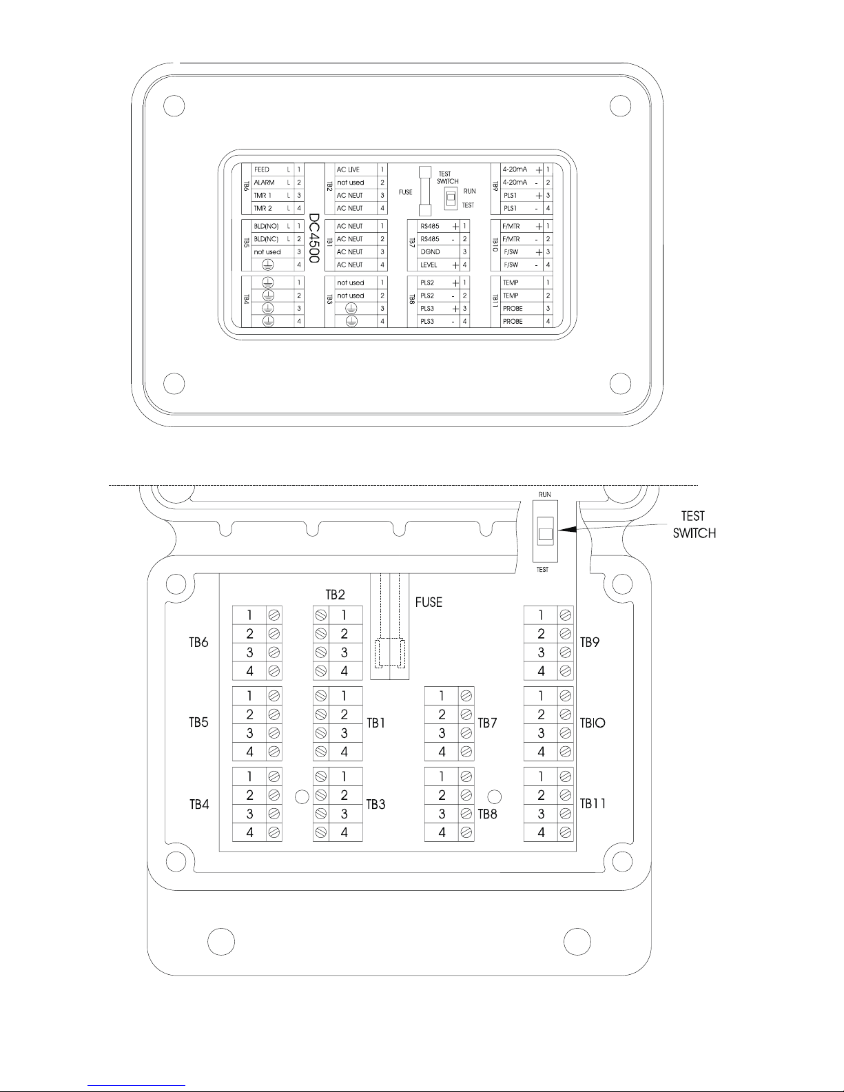
Figure 5: Bottom of controller with cover open.Figure 5: Bottom of controller with cover open.
(866) 433-6682 • (281) 359-8538 • sales@novatech-usa.com • www.novatech-usa.com
Figure 5: Bottom of controller with cover open.
Figure 5: Bottom of controller with cover open.Figure 5: Bottom of controller with cover open.
12

ALARM
(866) 433-6682 • (281) 359-8538 • sales@novatech-usa.com • www.novatech-usa.com
AC POWER
MOTORIZED
VALV E
SOLENOID VALVE
LINE(N.O.)
LINE(N.C.)
NEUTRAL
TB6
TB5
TB4
MAIN
POWER
INPUT
TEST SWITCH
RUN
TEST
1
TB2
2
3
4
1
2
3
4
1
2
3
4
FUSE
1
2
3
4
1
2
3
4
1
2
3
4
TB1
TB3
1
2
3
4
1
2
3
4
TB7
TB8
1
2
TB9
3
4
1
2
TBIO
3
4
RED
1
GREY
2
ORG
VIO
3
TB11
4
CHART RECORDER
4-20
MILLIAMP
OUTPUT
FLOWMETER
FLOW SWITCH
WHITE
GRAY
RED
BLACK
PROBE
FEED
BIO 1
BIO 2
DC4500
RUN
TEST
1
2
3
4
1
2
3
4
TB9
TB10 TB11
4-20mA
4-20mA
PLS1
PLS1
F/MTR
F/MTR
F/SW
F/SW
TEMP
TEMP
PROBE
PROBE
1
+
2
-
3
+
4
-
1
+
2
-
3
+
4
-
1
2
3
4
TB6
ALARM
TMR 1
TMR 2
BLD(NO)
TB5
BLD(NC)
not used
TB4
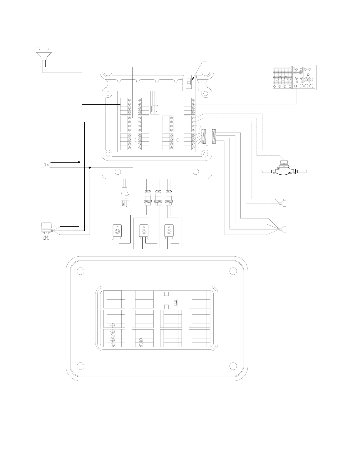
Wiring diagram for ON/OFF output control.Wiring diagram for ON/OFF output control.
Wiring diagram for ON/OFF output control.
Wiring diagram for ON/OFF output control.Wiring diagram for ON/OFF output control.
2
L
3
L
4
L
1
L
2
L
3
4
1
2
3
4
TB2
DC4500
TB1
TB3
1
L
FEED
AC LIVE
not used
AC NEUT
AC NEUT
AC NEUT
AC NEUT
AC NEUT
AC NEUT
not used
not used
1
2
3
4
1
2
3
4
1
2
3
4
FUSE
TEST
SWITCH
RS485
+
TB7 TB8
RS485
-
DGND
LEVEL
+
PLS2
+
PLS2
-
PLS3
+
PLS3
-
13
ALARM
(866) 433-6682 • (281) 359-8538 • sales@novatech-usa.com • www.novatech-usa.com
SOLENOID
VALVE
MOTORIZED
VALV E
AC POWER
AC POWER
LINE(N.O.)
LINE(N.C.)
NEUTRAL
TB6
TB5
TB4
MAIN
POWER
INPUT
FEED
TEST SWITCH
RUN
TEST
TB2
1
2
3
4
1
2
3
4
1
2
3
4
FUSE
1
2
3
4
1
2
3
4
1
2
3
4
TB1
TB3
1
2
3
4
1
2
3
4
TB7
TB8
1
2
TB9
3
4
1
2
TBIO
3
4
RED
1
GREY
2
ORG
VIO
3
TB11
4
CHART RECORDER
4-20
MILLIAMP
OUTPUT
FLOWMETER
FLOW SWITCH
WHITE
GRAY
RED
BIO 1
BLACK
BIO 2
PROBE
14
DC4500
RUN
TEST
1
2
3
4
1
2
3
4
4-20mA
1
+
TB9 TB10 TB11
4-20mA
2
-
3
PLS1
+
4
PLS1
-
1
F/MTR
+
2
F/MTR
-
3
F/SW
+
4
F/SW
-
1
TEMP
2
TEMP
3
PROBE
4
PROBE
TB6
ALARM
TMR 1
TMR 2
BLD(NO)
TB5
BLD(NC)
not used
TB4
Wiring diagram for external pulse output control.Wiring diagram for external pulse output control.
Wiring diagram for external pulse output control.
Wiring diagram for external pulse output control.Wiring diagram for external pulse output control.
2
L
3
L
4
L
1
L
2
L
3
4
1
2
3
4
TB2
DC4500
TB1
TB3
1
L
FEED
AC LIVE
not used
AC NEUT
AC NEUT
AC NEUT
AC NEUT
AC NEUT
AC NEUT
not used
not used
1
2
3
4
1
2
3
4
1
2
3
4
FUSE
TEST
SWITCH
RS485
+
TB7 TB8
RS485
-
DGND
LEVEL
+
PLS2
+
PLS2
-
PLS3
+
PLS3
-
 Loading...