

Page 1
LMI Corporation
DIGITAL INDICATOR
USER MANUAL
www.lmicorporation.com 1
Linear Measurement Instruments
101 N. Alloy Drive
Fenton, MI 48430
810-714-5811
www.lmicorporation.com
Page 2

TABLE OF CONTENTS
SECTION PAGE
1 INTRODUCTON…………………………………….………………………… 3
1.1 WARRANTY……………………………………………………………… 3
1.2 CONTACT INFORMATION…….……………………………………….. 3
1.3 AGENCY APPROVALS AND COMPLIANCE…………………………. 3
1.4 PRECAUTIONS…………………………………………………………… 4
1.5 PACKAGING CONTENTS……………………………………………….. 4
2 OVERVIEW ………………………………………………………………….. 5
2.1 INDICATOR OVERVIEW AND DIMENSIONS………………………… 5-8
2.2 OPERATING KEYS OVERVIEW………………………………………… 6
2.3 LCD DESCRIPT IONS……………………………………………………… 6
3 BATTERIES …………………………………………………………………… 9
3.1 BATTERY ICON…………………………………………………………… 9
3.2 CHANGING BATTERIES………………………………………………… 9
4 CHANGING CONTACT TIPS………………………….……………………. 9
4.1 OPTIONAL CONTACT TIPS…………………………………………… 10
5 INSTALLING LUG .…………………………………………………………. 10
6 MOUNTING THE DIGITAL INDICATOR ………………………………… 10
7 PROTECTIVE BOOT .………………………………………………………. 11
7.1 REMOVING THE PROTECTIVE BOOT ………………………………… 11
7.2 RE-INSTALLING THE RUBBER CONNECTOR PLUGS……………… 11
8 OPERATING PROCEDURES .………………………………………………. 12
8.1 ON/OFF……………………………………………………………………. 12
8.2 CHANGING +/- SIGN AND COUNTING DIRECTION………………… 12
8.3 CHANGING UNITS……………………………………………………… 12
8.4 ZERO/ABS – MEASUREMENT MODES………………………………. 13
8.5 SETTING THE PRESET VALUE………………………………………… 13
8.6 TOLERANCE JUDGEMENT MODE……………………………………… 14
8.7 SETTING/CHANGING THE TOLERANCE……………………………… 15
8.8 SENDING DATA…………………………………………………………. 16
8.9 LOCKING…………………………………………………………………. 16
9 CONNECTIONS/CABLE SPECIFICATIONS………………………………. 16-19
9.1 WIRELESS OPTION…………………………………………………… …. 19
10 WIRELESS INDICATOR ADDENDUM…………………………………….. 2 0
Copyright 2012 LMI Corporation Ver 3.0 6/29/2012
www.lmicorporation.com 2
Page 3

SECTION 1: INTRODUCTION
First of all LMI would like to thank you for purchasing a Diamondback Series digital indicator.
LMI values every customer and we look forward to working with you and serving your
measurement needs. We appreciate your feedback and strive to provide the highest customer
satisfaction with every tool we sell.
The LMI Diamondback Series digital indica tor is a precise measurement tool that was designed to
be used on the shop floor as well as the quality lab. To take full advantage of all the features
packed into the Diamondback indicator please read the manual completely. If any problems or
questions arise while reading the manual or operating the digital indicator, please feel free to
contact LMI Corporation. Keep the manual for future reference and for warranty information.
1.1 WARRANTY
It is the goal of LMI Corporation to meet or exceed its customer’s expectations toward our
products. If the digital indicator displays defective workmanship or material, it will be
covered under the warranty up to one year from date of original purchase. During the
warranty period we will repair or, at our option, replace at no charge the product, if the
product proves to be defective, provided it is returned, shipping prepaid to LMI. The
warranty does not apply to the digital indicator if it has been accidentally damaged or
misused or serviced or modified by anyone o ther than L MI Corporation. For any questions
or concerns regarding the warranty contact LMI Corporation
.
1.2 CONTACT INFORMATION
Hours of Operation: Monday through Friday 8am-5pm EST/DST
Phone: 810-714-5811
Fax: 810-714-5711
Website: www.LMIcorporation.com
EMAIL:
CUSTOMER SERVICES: [email protected]
SALES: sales@LMIcorporation.com
TECHNICAL SUPPORT: [email protected]
1.3 AGENCY APPROVALS AND COMPLIANCE
European Union Directives: The product described in this documentation complies with
the EU directives 73/23/EEC (Low Voltage Directive) and 89/336/EEC (EMC Directive)
and bears the CE Mark accordingly. The product has been tested and complies with the
requirements of EN 61326 (EN55011 1997 Class A) for Emissions and Immunity
.
www.lmicorporation.com 3
Page 4

1.4 PRECAUTIONS
Read the following precautions to prevent the digital indicator from being damaged and to
ensure proper functioning.
IMPORTANT
• Do not drop or apply excessive force to the indicator
• Do not subject the indicator to blows or knocks
• Do not disassemble or modify the indicator; warranty will be forfeited
• Do not use sharp objects to press the keys ; this could damage the keys and voi d your warranty
• Avoid excessively cold or hot climates
-Allow sufficient time for the indicato r to thermally stabilize if the indica tor has moved
between environments with different temperatures; Allow approximately 2 hours at room
temperature to stabilize
-Operating temperature: 10 ~ 40 degree C (50 ~ 104 degree F)
-Storing temperature: -10 ~ 50 degree C (14 ~ 122 degree F)
• Protect data ports with rubber cap when not in us e
• Avoid using aro und high vol tage equipment
• Do not apply excessive force to spindle
• Use alco hol a nd soft cloth to clean spindle
• Do not put oil on spindle
• Dirt or de bris will interfere with the moveme nt of the spindle
Safety and Precautions on LCD and Battery Disposal
• A Liquid Crystal Display (LCD) is used in this product; When disposing, follow the ordinances or
regulations of the respective local government
• The Liquid Crystal Display contains irritating substances; Should the substance accidentally come
into contact with the eye or skin, rinse with clean, running water; If the substance gets i nt o the
mouth, immediately rinse out the mo ut h, and contact a local physician; DO NOT SWALL OW THE
SUBSTANCE.
• Batteries supplied are not rechargeable
• Keep batteries away from heat and fires, which may cause batteries to leak or explode
• Do not mix battery types
• ONLY USE AAA alkaline batteries
• Make sure polarities are correct when installing new batteries
• Remove batteries if indicator will not be used for long periods of time
1.5 PACKAGING CONTENTS
The package should be inspected immediately to verify that all of the parts are accounted for and no
damage exists. If anything is missing or damaged, co ntact LMI Corporation immediately. The
package should consist of the following:
o LMI Diamondback Digital Indicator
o CD-ROM consisting of a user manual and important USB drivers
o Certificate of Calibration
o (2) AAA Alkaline Batteries
www.lmicorporation.com 4
Page 5
SECTION 2: OVERVIEW
Example:
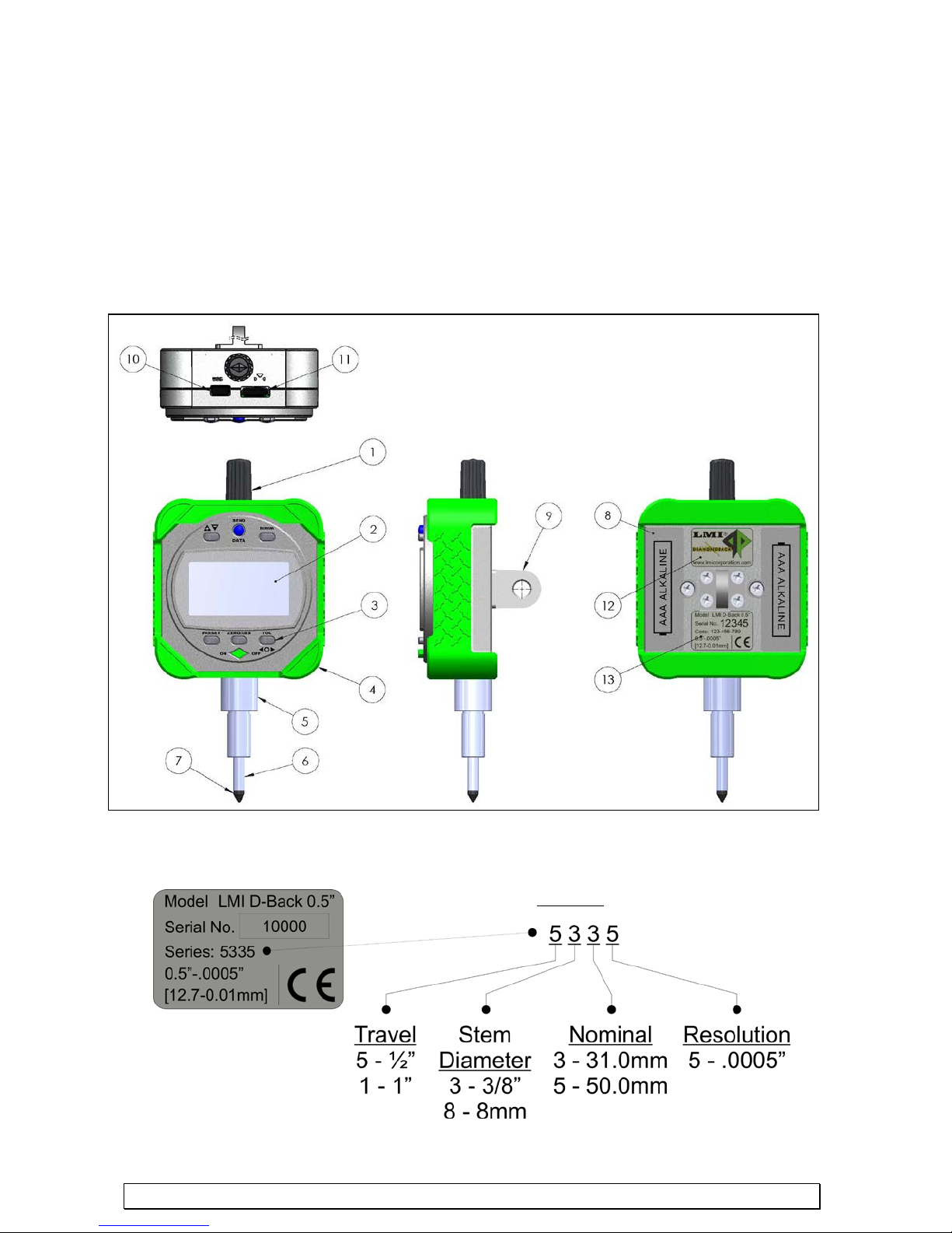
2.1 INDICATOR OVERVIEW AND DIMENSIONS
1. Top Cap 7. Contact Point
2. LCD Screen 8. Battery Cover (2)
3. Function Keys 9. Mounting Lug (optional)
4. Protective Boot 10. USB Port
5. Stem 11. Serial Port and Digimatic Port
6. Spindle 12. Product Label
13. Identification Label
Here is a break down of the identification label:
www.lmicorporation.com 5
Page 6
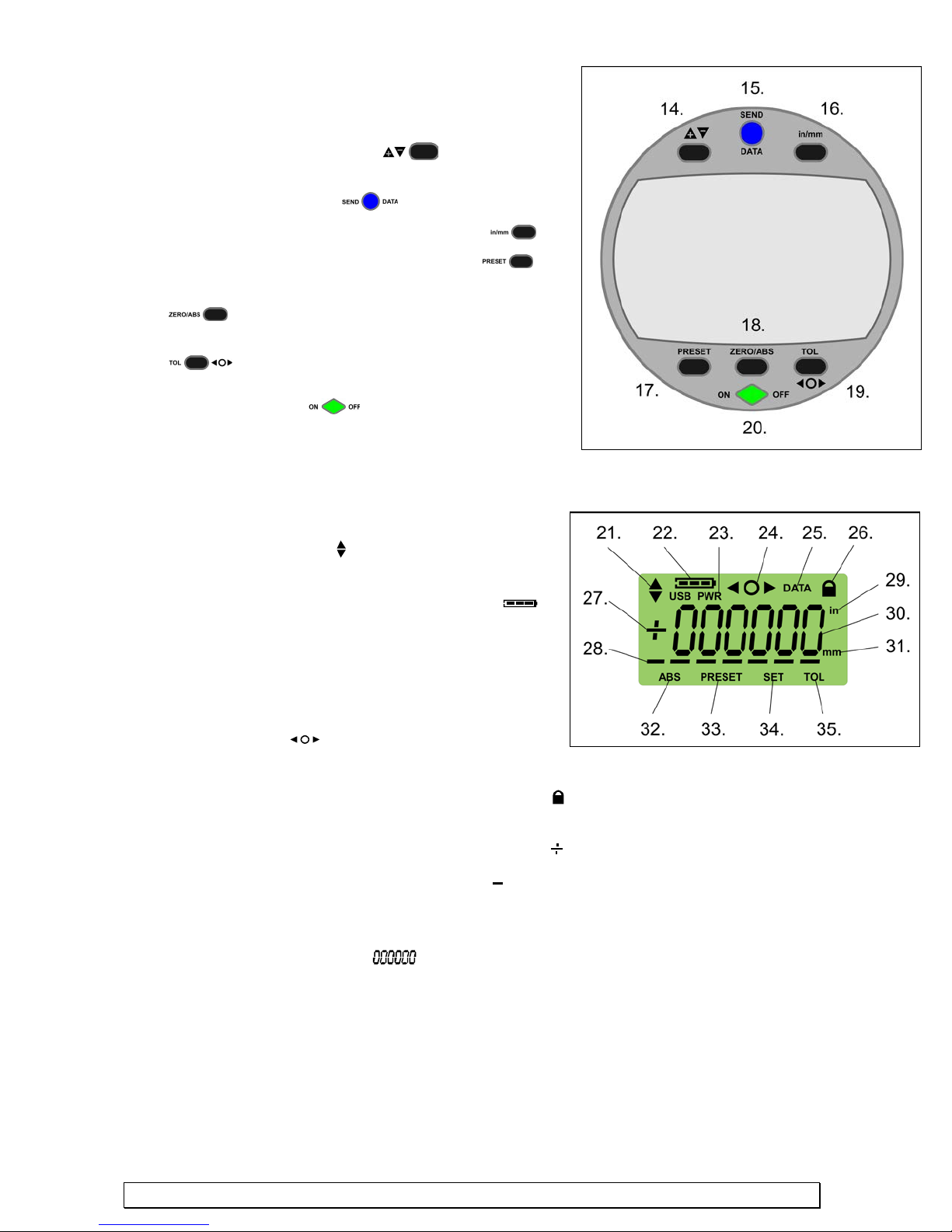
2.2 OPERATING KEYS OVERVIEW:
PWRUSB
DATA
in
mm
ABS
PRESET
SET
TOL
14. +/-: toggles between negative and positive values and
changes the counting direction
15. SEND DATA: sends data through the output ports
Serial/Digimatic or USB
16. in/mm: toggles between inches and millimeters
17. PRESET: recalls and resets a reference value
18. ZERO/ABS: toggles between ABSsolu te and ZERO Mode
19. TOL: toggles tolerance mode and resets tolerance limits
20. ON/OFF: turns the indicator on and off and locks out
button functionality
2.3 LCD DESCRIPTION
21. Directional arrows, display which direction the
indicator is measuring (
contact point moves in direction of arrow)
22. Battery icon, displays power level of batteries (
23. USB PWR indicator, appears when a USB connector is
plugged in and the indicator is powered by USB port
(
)
) (i.e. value increases when
)
24. Tolerance Symbols, (only visible in TOL mode)
displays greater than, less than or equal to the set
tolerance limits (
25. DATA, appears when data is being sent (
26. LOCK, appears when the indicator is in LOCK mode (
are active
+/-, displays whether the value is positive or negative ( )
27.
28. Underscore, appears when a digit is selected (
29. in, displays when measuring in inches (displays four digits after the decimal; last digit can
only display a 0 and 5) (
30. Numerical values location ( )
31. mm, displays when measuring in millimeters (displays two digits after the decimal)
32. ABS, appears when in ABSOLUTE mode
33. PRESET, appears when changing the preset value (
34. SET, appears when resetting a value (
)
)
)
) Only the On/Off and Send buttons
) (Used to set TOL/PRESET Values)
(
(
)
)
) (flashes for a portion of the TOL/PRESET
setup operations)
35. TOL, appears when in TOLERANCE mode (
)
)
www.lmicorporation.com 6
Page 7
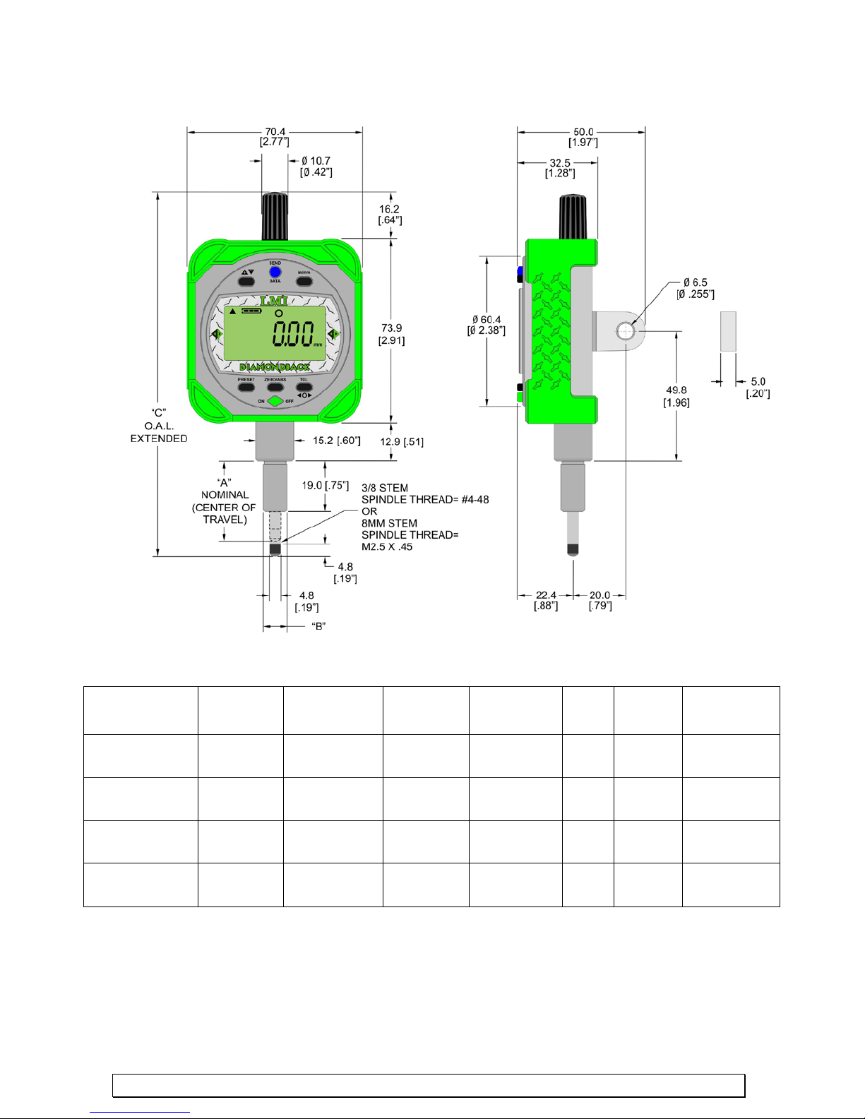
½” Travel Indicator Dimensions
Model Travel Resolution Accuracy
LMI D-Back
5335
LMI D-Back
5355
LMI D-Back
5835
LMI D-Back
5855
½”
12.7mm
½”
12.7mm
½”
12.7mm
½”
12.7mm
.0005”
.01mm
.0005”
.01mm
.0005”
.01mm
.0005”
.01mm
.0004”
.01mm
.0004”
.01mm
.0004”
.01mm
.0004”
.01mm
Measuring
Force
1.0N or
less
1.0N or
less
1.0N or
less
1.0N or
less
A B C
31.0 3/8”
50.0 3/8”
31.0 8.0mm
50.0 8.0mm
146.6mm
165.6mm
146.6mm
165.6mm
5.77”
6.52”
5.77”
6.52”
www.lmicorporation.com 7
Page 8
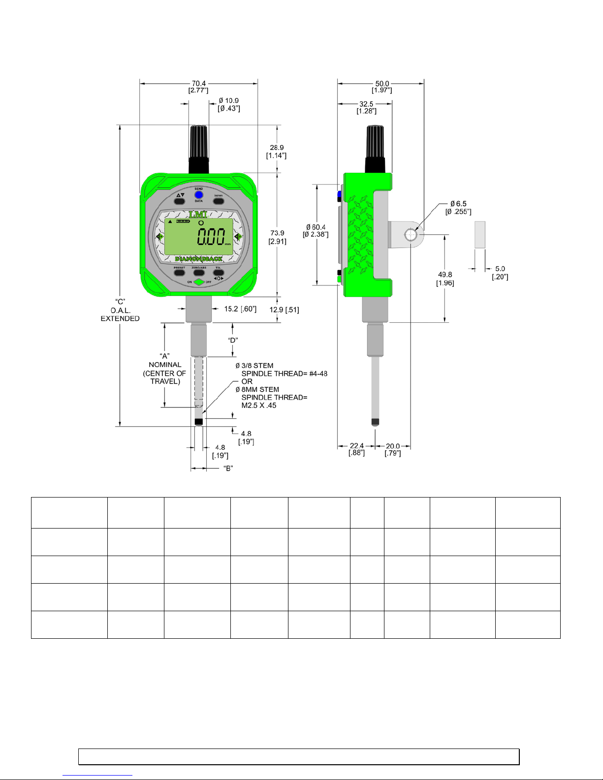
1” Travel Indicator Dimensions
LMI D-Back
1335
1.0”
25.4 mm
.0005”
.01mm
.0008”
.02mm
1.9N or
less
6.27”
159.3mm
.53”
13.3mm
LMI D-Back
1355
1.0”
25.4 mm
.0005”
.01mm
.0008”
.02mm
1.9N or
less
7.02”
178.3mm
.75”
19.0mm
LMI D-Back
1835
1.0”
25.4 mm
.0005”
.01mm
.0008”
.02mm
1.9N or
less
6.27”
159.3mm
.53”
13.3mm
LMI D-Back
1855
1.0”
25.4 mm
.0005”
.01mm
.0008”
.02mm
1.9N or
less
7.02”
178.3mm
.75”
19.0mm
Model Travel Resolution Accuracy
www.lmicorporation.com 8
Measuring
Force
A B C D
31.0 3/8”
50.0 3/8”
31.0 8.0mm
50.0 8.0mm
Page 9
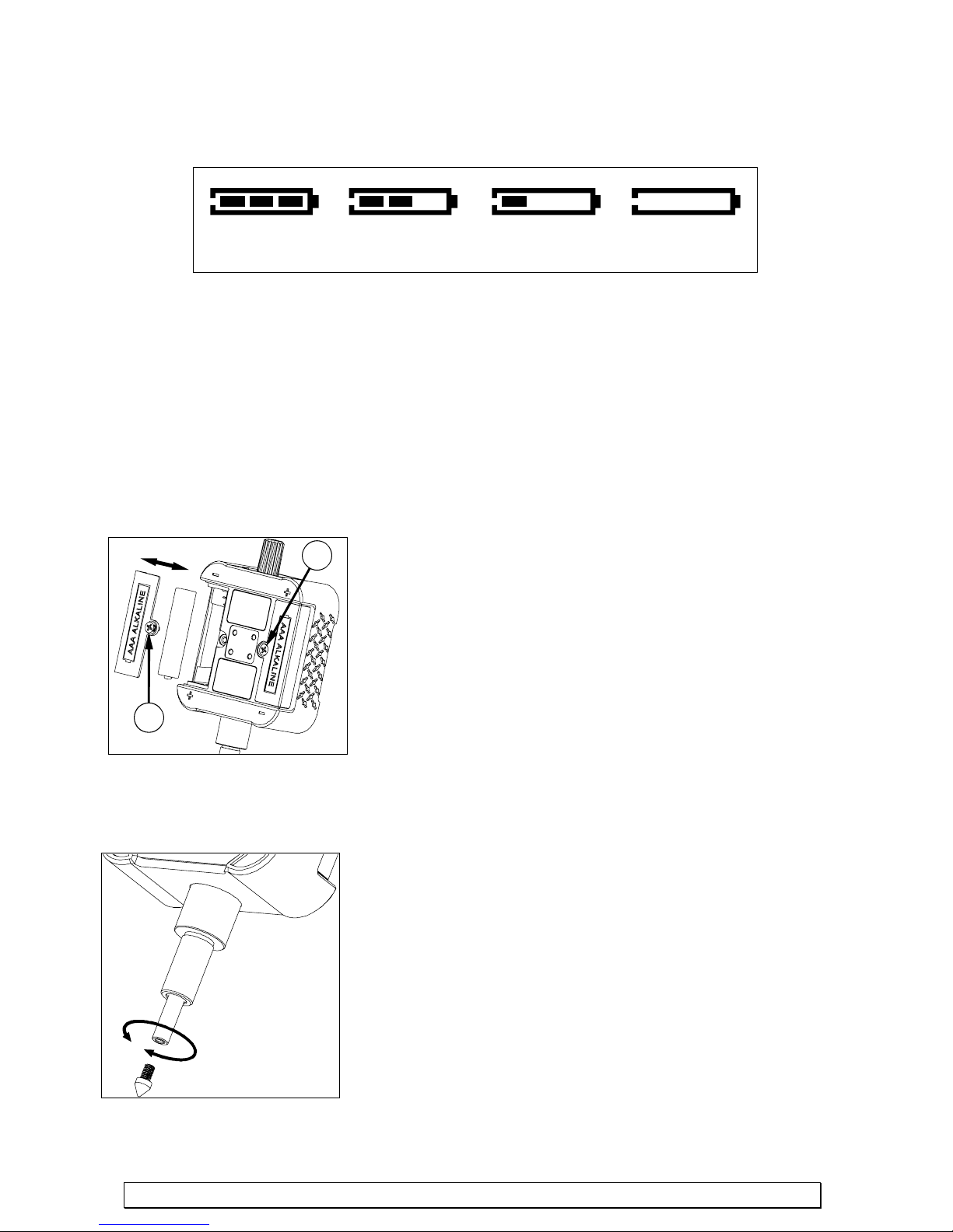
SECTION 3: BATTERIES
FULL 2/3 Capacity 1/3 Capacity DEPLETED
Replace Battery
2
2
3.1 BATTERY ICON
The battery icon indicates the condition of the batteries in the unit. The battery power level is
divided into three segments (se e illustration above). As the batteries are depleted the display will
change as illustrated above. Depleted batteries must be replaced when all indicators have gone from
the display. If the indicator is connected with a USB cable; a USB PWR icon will display below the
battery icon. The unit is now powered via USB. Batteries are not required in this mode. Note: Data
will be lost if USB cable is removed and the batteries are depleted or missing.
3.2 CHANGING BATTERIES
When putting in new batteries, the dig it a l ind ic a tor will store the tolerance limits, preset
values, and the mode the di gital indicator was in before the batteries were replaced.
1. Verify that the unit is turned off.
2. Flip the digital indicator over so the LCD is facing down.
3. Using a philips screwdriver, turn screw counterclockwise to
release cover.
NOTE: Screws will remain attached to cover.
4. Remove battery cover.
5. Pull out the old batterie s and replace them with new AAA
alkaline batteries only.
6. Ensure that the polarities are correct, when installing the
batteries. Polarity +/- is clearly marked on the unit.
SECTION 4: CHANGING CONTACT TIPS
1. Hold the spindle with a pair of pliers and a clean piece of cloth
and with another pair of pliers holding the tip; turn the tip
counter clock wise to remove.
2. Place the tip on the spi nd le a nd turn the tip to the right to tighten.
Then hold the spindle with a pair of pliers and a clean piece of
cloth and with another pair of plier s holding the tip; tighten the
tip to ensure that it is secure. Do not over tighten t ip.
www.lmicorporation.com 9
Page 10
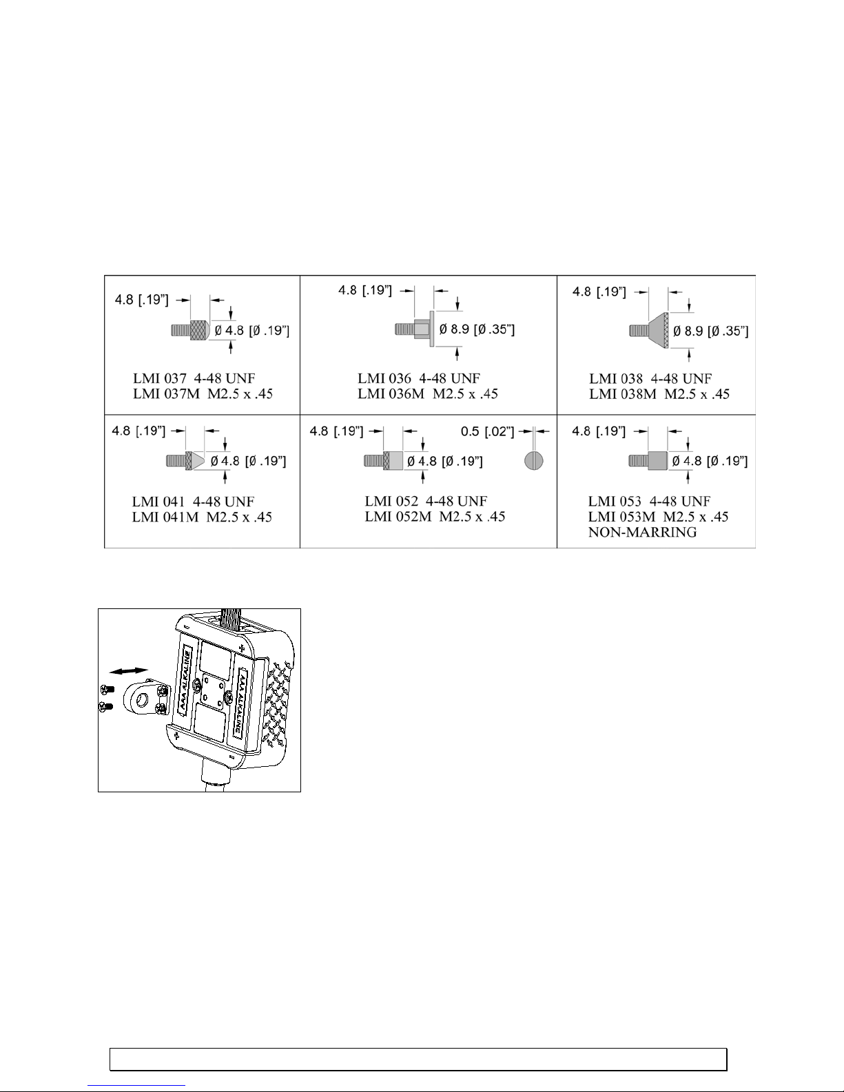
4.1 OPTIONAL CONTACT TIPS
LMI offers a variety of optional tips to fit the Diamondback Series indicators (LMI 037 Tip
shipped standard on all Diamondback models). Each model is designed to be virtually
indestructible by using our unique two piece construction. These durable tips come in #448UNF and M2.5x0.45 threads.
Caution: Other commercially available tips will fit the Diamondback Series indicator but
they are not robust and should be avoided. If the indicator is dropped the tip may shear off
leaving the threaded shank inside the spind le and wil l require the ind ica tor to be sent in for
repair.
SECTION 5: INSTALLING THE LUG
An optional mounting lug (Part no. LMI D-Back Lug) can be purchased
for the indicator. T o install the lug, turn the indicator so that the LCD is
facing down. Align the lug on the recessed area centering the fo ur screw
holes. Install the screws in the holes. For pricing or to order the lug,
please contact LMI Corporation.
SECTION 6: MOUNTING THE DIGITAL IND IC A T OR
Secure the digital indicator by using the back lu g or secure the stem using a split mounting block or c ollet.
Do not over tighten the split mounting block; this could cause serious damage to the spindle. Do not apply
excessive force to the stem; this will damage the stem and possibly the spindle.
Attention: Do not clamp the indicat or using a screw directly onto the stem, this will damage the stem and
possibly prevent smooth operation of the spindle.
www.lmicorporation.com 10
Page 11
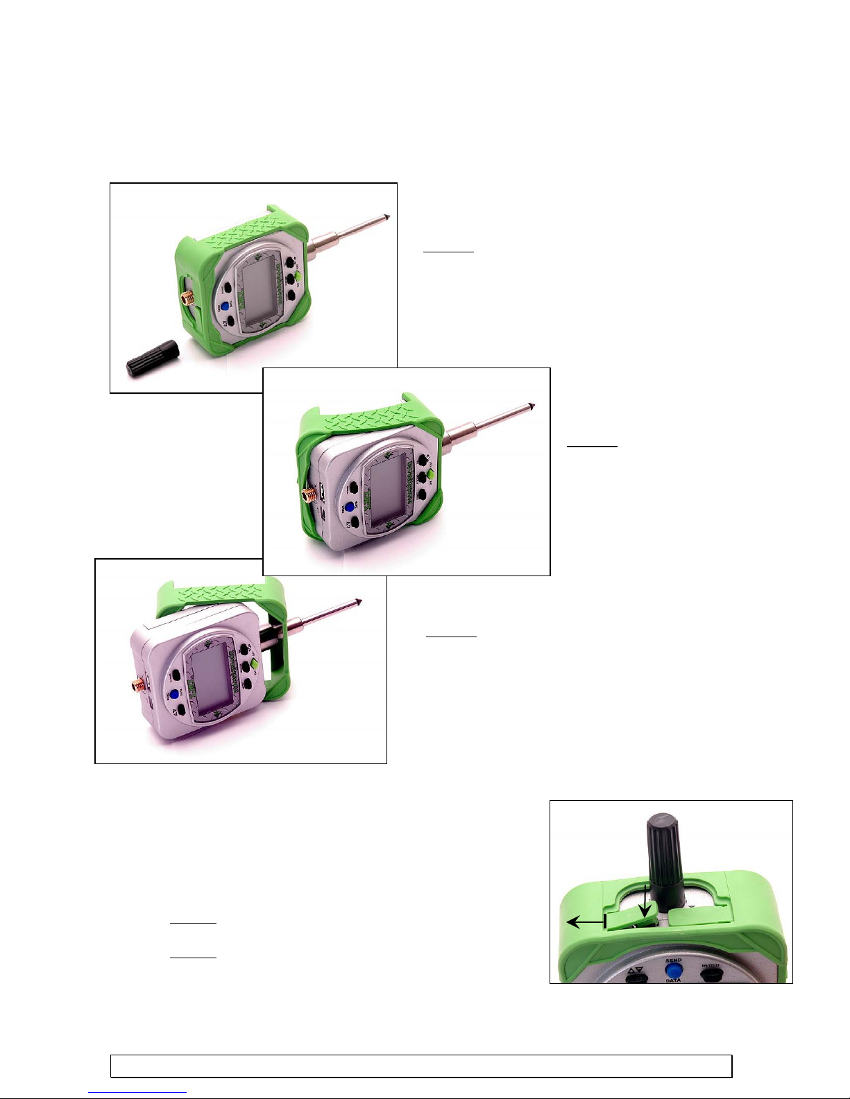
SECTION 7: PROTECTIVE BOOT
Step #2 – Peel back the two top
lift off towards the
Step #1 – Unscrew and remove the
Step #3 – Continue removing the boot from
#1
#2
7.1 REMOVING THE PROTECTIVE BOOT
It may be necessary at some point to remove the protective rubber boot. Follow the steps below to
properly remove the boot. To replace the boot simply reverse the steps.
7.2 RE-INSTALLING THE RUBBER CONNECTOR PLUGS
If a cable is not being used and plugged into the connector ports,
the rubber plugs should be re-installed to keep the connectors
clean. The rubber plugs were designed to be a tight fit to keep
out dirt and grime to give you years of shop floor use. But there
is a simple technique to re-install the p lugs.
Step #1 – Pull the tab back and line up to the edge of the
connector
Step #2 – Push down on top to insert plug, with a wiggle
motion to seat the plug
top cap
corners of the boot and
back of the indicator.
the back while sliding the boot
down the stem and off the spindle
www.lmicorporation.com 11
Page 12
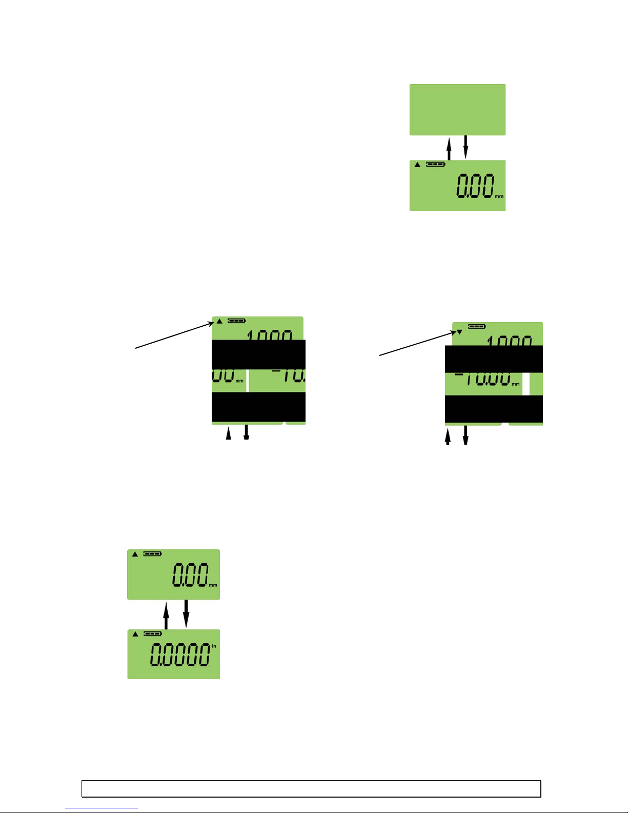
SECTION 8: OPERATING PROCEDURES
This picture illustrates the indicator in
When the arrow is pointing
When the arrow is pointing
OFF
ON
8.1 ON/OFF
To turn on the indicator, press and release the ON/OFF
button. To turn off the indicator, press and release the
ON/OFF button. The digital indicator will turn on in the
same mode it was in before it was turned off and the
selected values for tolerance and preset will be kept. Except
when in a setup mode, such as the mode for setting the
preset value, if the digital indicator is turned off, then the
digital indicator will enter the mode it was in before it
entered the preset value mode.
8.2 CHANGING +/- SIGN AND COUNTING DIRECTION
To change the positive and negative value, pr ess and release the +/- button and the s ign will change
to the left of the value. This will also change the counting direction the indicator measures and the
arrows indicate the direction of increasing values.
up, the values are increasing
as the spindle moves inward.
8.3 CHANGING UNITS (in/mm)
To the right of the numbers is the unit of measurement. To change the unit of measurement,
press and release the in/mm button.
NOTE: mm/in have the maximum of six digits.
down, the values are
increasing as the spindle
moves outward.
www.lmicorporation.com 12
mm Mode
This picture illustrates the indicator in
inches Mode
Page 13
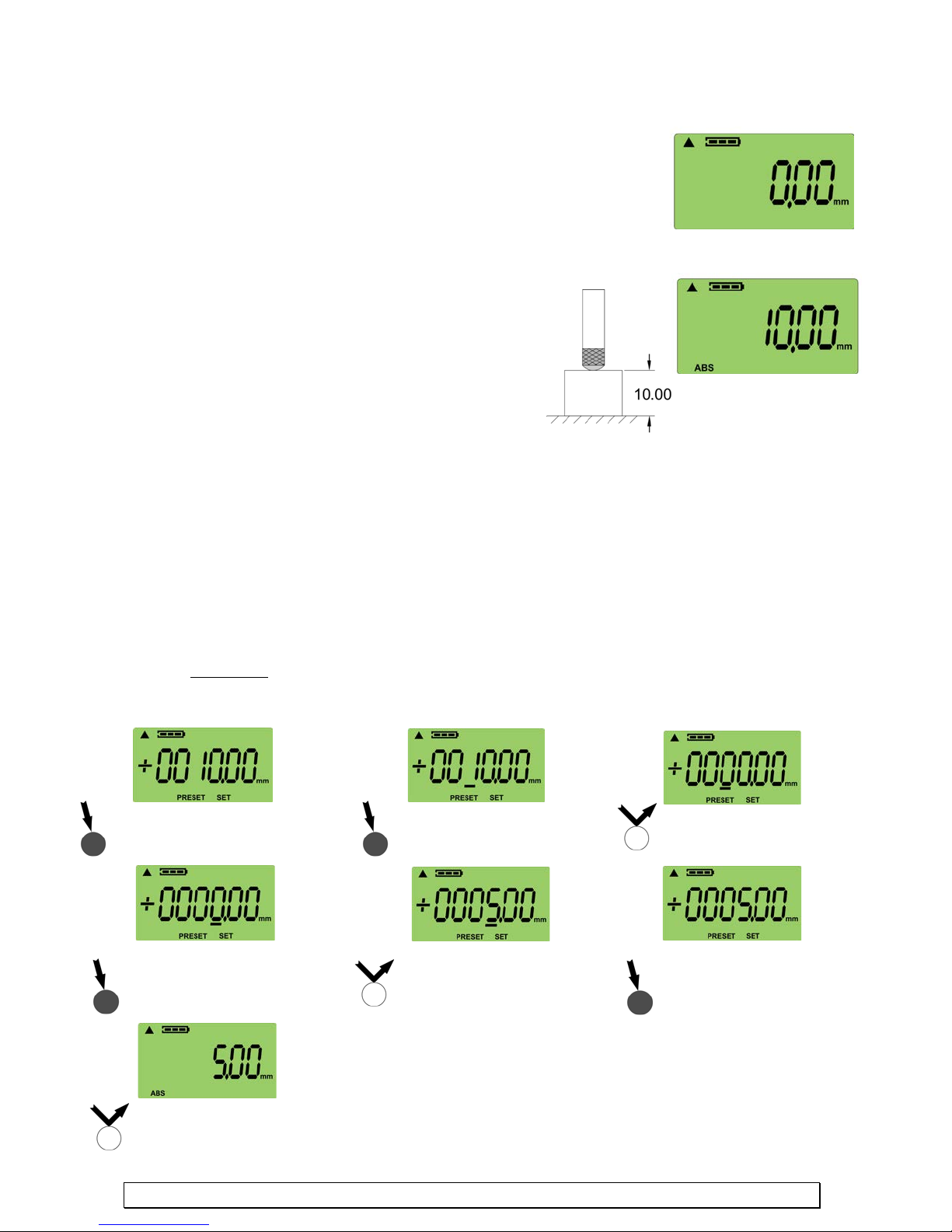
Press and hold PRESET
8.4 ZERO/ABS – MEASUREMENT MODES
Press and hold PRESET for 3
Press and hold PRESET
Press and release PRESET
becomes a five.
Press and hold PRESET
Press and release
Press and release
ZERO Mode
ABS Mode
The digital indicator has two modes to take measurements. ZERO
Mode (also known as INCremental Mode) is used to take
measurements from a value of zero. ABS or Absolute Mode is used to
take measurements from a Preset value.
To enter ZERO Mode, press and release the ZERO/ABS button. The
LCD will display all zeros.
To enter ABS Mode, press and release the PRESET
button. Press and release the P RESE T button will take
the current position of the spindle and assign it your
Preset value. The ABS ico n will appear in the bottom
left corner of the LCD. The default Preset value is
10.0mm. To change the Preset see section 8.5.
If you switch to ZERO Mode and want to re turn to
your last Preset stem position in ABS Mo de press and
hold the ZERO /ABS butto n for 3 seconds.
NOTE: Tolerance Mode can be used with ZERO Mode and ABS Mode
8.5 SETTING THE PRESET VALUE
To change the PRESET value, press and hold the PRESET butt on for 3 seconds. The previous value
will be displayed. Press and hold the PRESET button to select the digit you want to change. Press
and release the PRESET button to change the value. When finished, press and hol d the PRESET
button unti l none of the d igits are underscored and SET is flashing. Press and release the PRESET
button and the value will be set. Note that if yo u set the PRESET value to the max (99 99.99 mm or
99.9995 in) and the measurement exceeds those values, then the LCD will display “Err-OL”,
meaning a character overload.
EXAMPLE:
For this example, we are going to change the default PRESET value of +10.00 to the new value of +5.00mm.
seconds. The previous value
will display. SET will flash
until the underscore is
under the fourth digit.
PRESET. The new
value is now 5.00mm.
www.lmicorporation.com 13
until the underscore is
under the o ne.
until the fourth digit
PRESET until the digit
becomes a zero.
until the underscore is
gone and SET starts to
flash.
Page 14
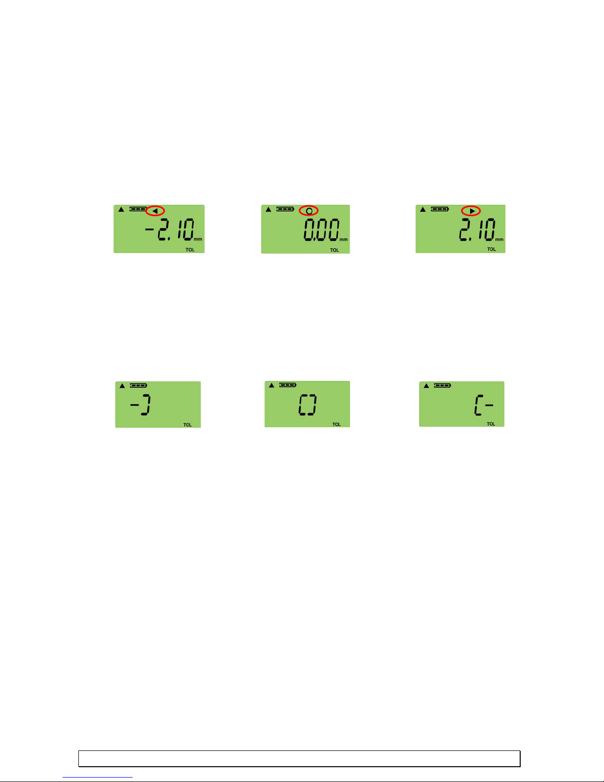
8.6 TOLERANCE JUDGMENT MODE
Measured value
Lower Limit
Measured value is with
Measured value is
Upper Limit
Measured value
Lower Limit
Measured value is with
Measured value is
Upper Limit
Tolerance Judgment Mo de will di s play whether the measur ed value is within the tolerance limits
that have been set by the user. The TOL icon will display in the bottom right hand corner of the
LCD when in Tolerance Judgment Mode. There are two different ways of viewing the Tolerance
Judgment Mode, with and without numerical values. Press and release the TOL button to change
the view or turn Tolerance Judgment Mode off. See 8.7 to set the tolerance limits.
DISPLAYING TOLERANCE JUDGEMENT WITH NUMERICAL VALUES
To display the tolerance judgment with numerical values, press and release the TOL button. The
tolerance symbols will appear in the upper middle section of the LCD.
is less than the
DISPLAYING TOLERANCE JUDGEMENT WITHOUT NUMERICAL VALUES
In order to display the tolerance judgment without numerical values make sure the digital indic a tor
is in TOL mode and is displaying the tolerance with numerical values, then press and release the
TOL button and the tolerance brackets will appear.
is less than the
in tolerance
in tolerance
greater than the
greater than the
www.lmicorporation.com 14
Page 15
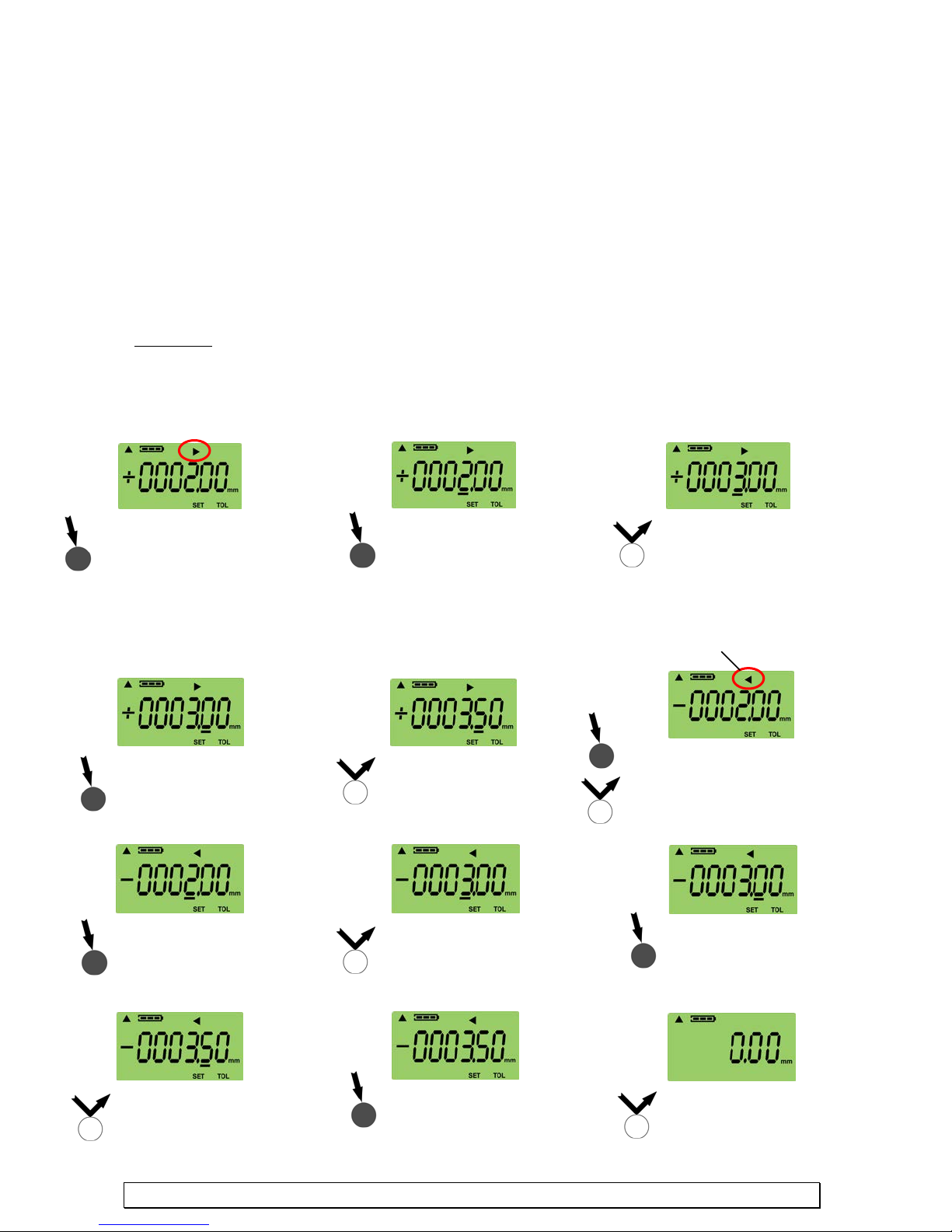
8.7 SETTING/CHANGING TOLERANCES LIMITS
Press and hold TOL for 3
Press and hold TOL
Press and release TOL
three.
Press and hold TOL
Press and release TOL
1. Press and hold TOL until the
Press and hold TOL
Press and release TOL
three.
Press and hold TOL until
Press and release TOL
Press and hold TOL
Press and release TOL
To enter the mode that changes the tolerance value, Press and hold the TOL button for 3 seconds.
The previously set value will display. The default values are +2.00mm and -2.00 mm. Press and
hold the TOL button until the underscore is b e low the digit you wo uld like to c hange. Pre s s and
release the TOL button to change the value of the digit to the desired value. When you a re finishe d,
press and hold the TOL button until none of the digits are underscored and SET is flashing. Press
and release the TOL button and the new values will be set. Be aware that there are two values, the
first value to be displayed is the Upper Limit a nd the second value to be displayed is the Lower
Limit.
NOTE: the Lower Limit cannot be greater than or equal to the Upper Limit. (an error will be
displayed if attempted)
EXAMPLE:
For this example, we are going to change from the default values of +2.00mm and -2.00mm so that the Upper
Limit is +3.50mm and the Lower Limit is -3.50mm.
Note: Arrow pointing to the right indicates setting the Upper Limit
seconds. The previous Upper
Limit will be displayed and
SET will flash.
until the underscore
is under the fourth
until the fourth digit reads
Note: Arrow pointing to the
left indicates setting the
Lower Limit
until the underscore
appears under the fifth
digit.
until the fifth digit reads
five.
underscore is gone. SET will flash.
2. Press and release TOL and the Lower
Limit and arrow icon will display
until the underscore is
under the fourth digit.
until the fifth digit reads
five.
www.lmicorporation.com 15
until the fourth digit reads
until the underscore is
gone. SET will flash.
the underscore is under
the fifth digit.
and the new U pper and
Lower Limits are set
Page 16
8.8 SENDING DATA
“UNLOCKED”
“LOCKED”
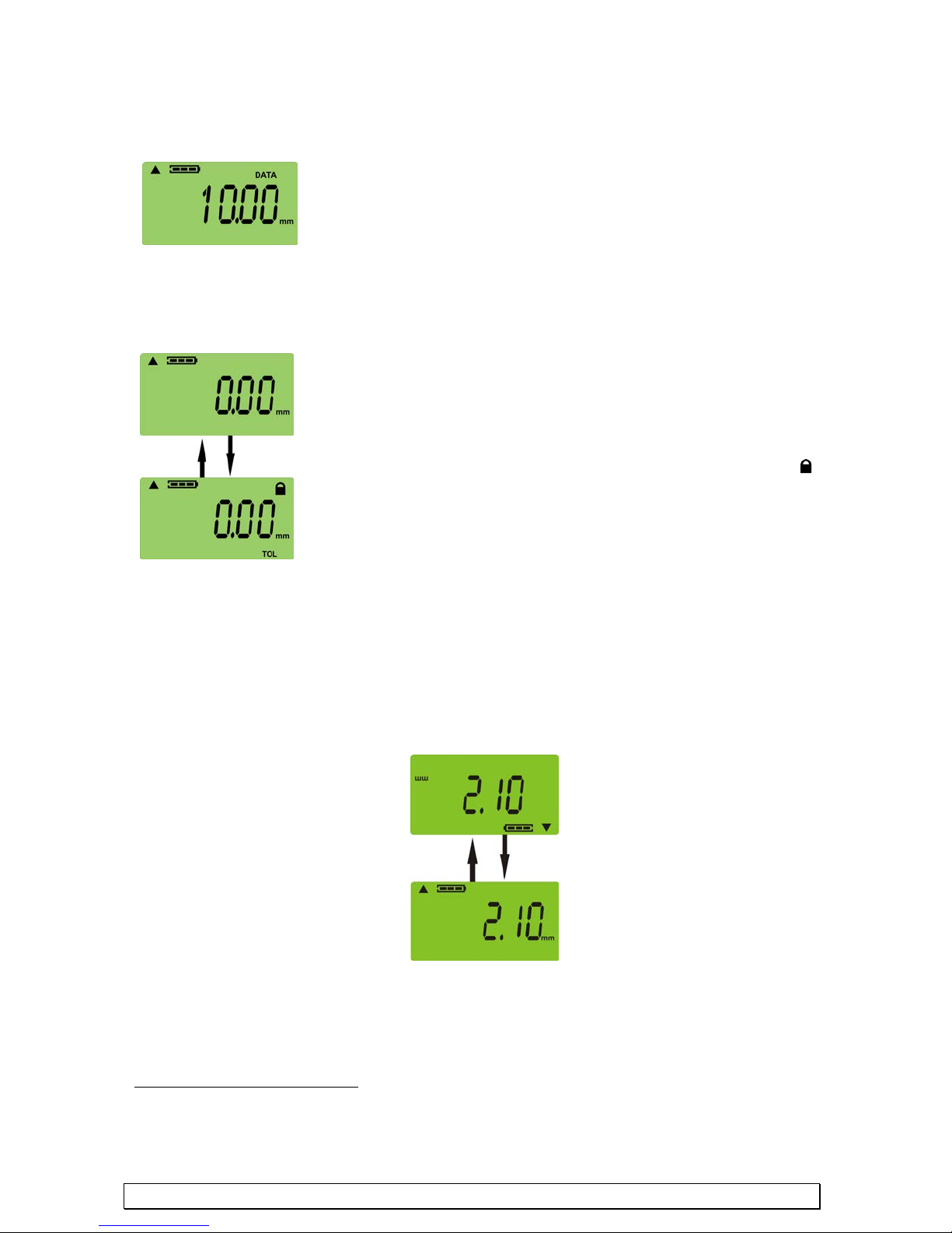
The Lock Mod e is very useful to limit the functions once the
the ON/OFF button and all the functions will return to each
“SCREEN FLIPPED”
“NORMAL SCREEN”
The digital indicator can send data by USB, Digimatic, or RS232. The ports to connect the cables
are located on top of the indicator. Please see SECTION 9 for specific details on connections.
1. Remove the rubber cap off the connector that is to be used.
2. Plug in the corresponding plug to the connector.
3. Turn on the digital indicator.
4. When read y to send data, press the Send button on the digital indicator.
NOTE: When the digital indicator is sending data the DAT A symbol will appear until the data is
completely sent. T he DATA icon will only display when a ca ble is plugged into the indicator.
8.9 LOCKING
indicator is properly set up and to avoid any unintentional
changes. In the Lock Mode the digital indicator can be turned
on/off and send data, but all the other functions will be locked
out. To Lo ck your indicator make sure the unit is power on.
Press and hold the ON/OFF button and the Lock i con
appear in t he upper right hand corner. To Unlock, press and hold
8.10 SCREEN FLIP
The digital indicato r LCD screen can be Flipped so that the s cr een can be read regardless of how the
indicator is entered into a part. To Flip/Invert the LCD hold the +/- button down for 3-5 seconds
until the screen has Flipped. To Flip the screen back again ho ld the +/- button for 3-5 seconds.
When the screen is flipped, o nly the reading will flip. No other icons will flip on the LCD screen.1
will
1
In the nor mal Screen mode when set to inches the resolution of display on the LCD is 4 decimal
places, in the Flip mode the resolution of display is only 3 decimal places.
www.lmicorporation.com 16
Page 17
SECTION 9: CONNECTIONS/CABLE SPECIFICATIONS
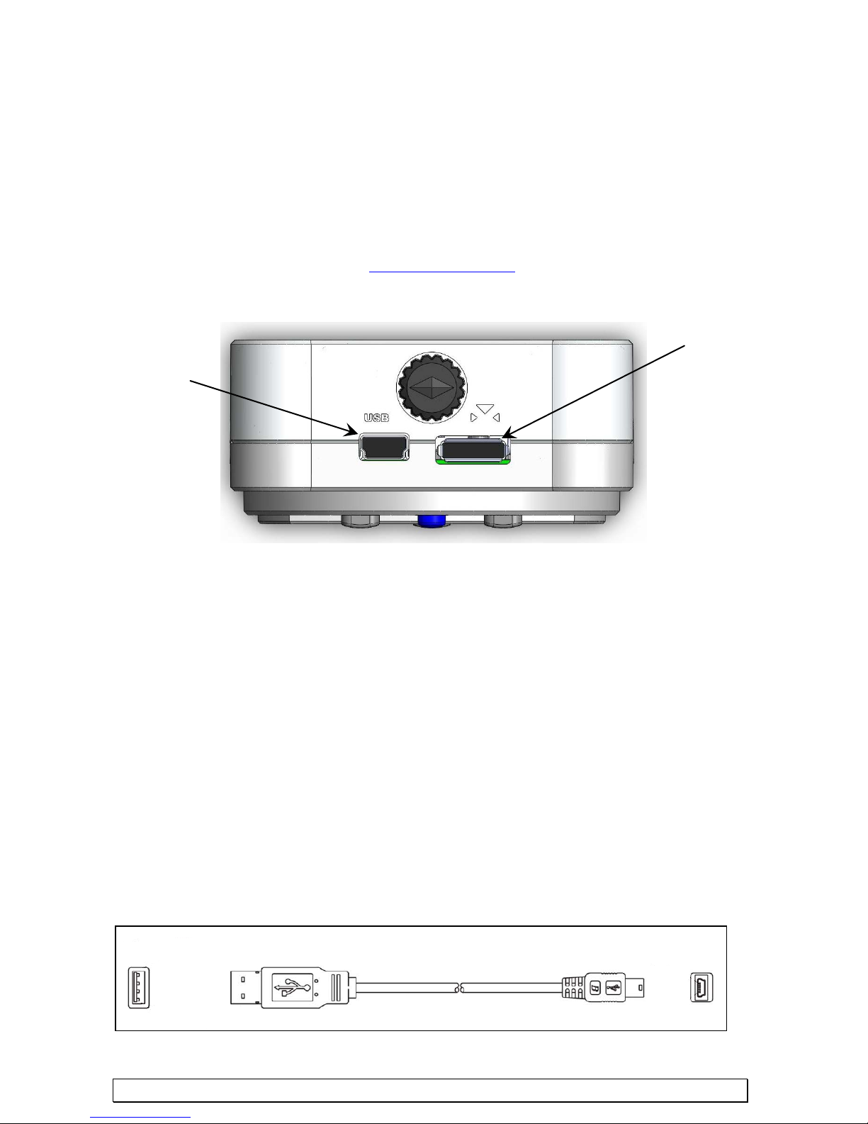
USB Connection
RS232 and
LMI 6026 Cable
USB A to MINI USB B
LMI offers a variety of software and hardware solutions to collect data or even multiplex the Diamondback
Series indicators. Contact LMI to provide you with the most efficient solution.
There are three methods that can be used for transferring data from the unit to a base unit, such as a PC. The
methods for transferring data are USB using the LMI 6026 cable, Digimatic using the LMI 6028 cable and
RS232 using the LMI 6027 cable.
Note that the cables are not included, but may be purchased from LMI Corporation. In order to communicate
using a USB cable the PC requires a driver to be installed. The drivers may be installed from the C D-ROM
that was included or on the LMI’s web site www.lmicorporation.com
CONNECTIONS
Powers unit and
receives data
.
Digimatic Port
USB
USB is a virtual COM-Interface. Drivers will be require d for the digital indicator to communicate to the PC.
To install the drivers, insert the CD-ROM that came with the digital indicato r. Click on the Install Drivers tab
and click on Install Drivers again. Once the drivers are loaded, the digital indicator will be able to
communicate via USB. The drivers will emulate a virtual COM-Port for every indicator that is connected to
the PC. The application software communicates to the instrument in exactly the same manner as a normal
hardware COM-port.
The default baud rate for using a USB connection through a virtual com port is 57600 bits per second. You
can change the baud rate to 9600 bits per second by pressing and holding the SEND button for 5 seconds.
The LCD screen will highlight all the characters indicating that the baud rate has been changed. The baud
rate will remain changed even after the unit is powered off. Press and hold the SEND button again until the
LCD highli ghts to change the baud rate back t o 57600.
Data format: [Reading] followed by Carriage Return i.e. 5.00 {CR}
COM Settings: Baud Rate 57600, parity: none, stop bit: 1, and data bits: 8
Press and Hold (5 seconds) the SEND button to switch the baud rate to 9600 bps
www.lmicorporation.com 17
Page 18
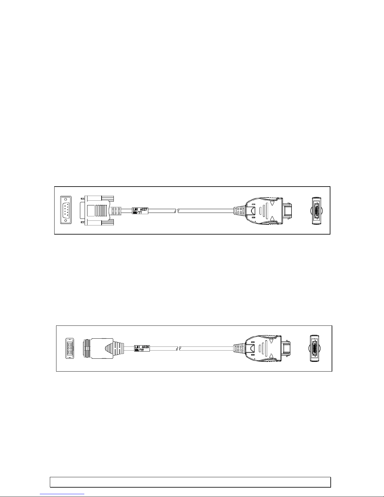
LMI 6028
LMI 6027
RS232
The RS232 port is used to connect the digital indicator directly to a PC COM port. For this type of
connection, an LMI 6027 cable will be required. The cable will plug into the top right hand port. Align the
triangles ic ons marked on the connector and the indicato r. Then plug the D Sub 9 Pin connector into a
standard PC COM port.
The default baud rate for communicating to a com port is 57600 bits per second. You can change the baud
rate to 9600 bits per second by pressing and holding the SEND button for 5 seconds. The LCD screen will
highlight all the characters indicating that the baud rate has been changed. The baud rate will remain
changed even after the unit is powered off. Press and hold the SEND button again until the LCD highlights
to change the baud rate back to 57600.
Data format: [Reading] followed by Carriage Return i.e. 5.00 {CR}
COM Settings: Baud Rate 57600, parity: none, stop bit: 1, and data bits: 8
Press and Hold (5 seconds) the SEND button to switch the baud rate to 9600 bps
DB9 to 10 Pin Indicator Plug
Digimatic
The Digimatic port is used to connect t he d igital indicator to a Mitutoyo co mpatible device. For connecting
via Digimatic, an LMI 6028 cable will be required. The cable will plug into the top right h and port. Align
the triangles icons marked on the connector and the indicator. Then plug the 10 pin (2 x 5) box header into
the Digimatic device. The data conforms to the Mitutoyo Digimatic protocol.
10 Pin (2 x 5) Box Header to 10 Pin Indicator Plug
www.lmicorporation.com 18
Page 19
[REQ]
[REQ]5.53{CR}
[ZERO]
[ZERO]
[STRM]
[STRM]8.04{CR}
8.04{CR}
8.04{CR}
8.04{CR}
8.04{CR}
8.04{CR}
8.04{CR}
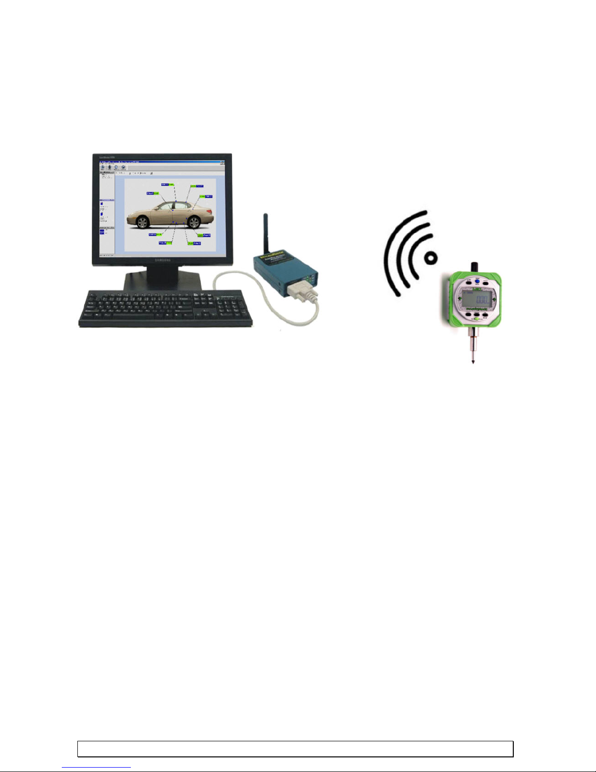
9.1 WIRELESS OPTION (via add-on Mobile Module)
An add-on wireless module is available from LMI to send d a ta wirelessly to a PC. The wireless
module plugs directly into the ser ia l port on the indicator and attaches to the back of the indicator.
The module is battery operated and will last for over 250,000 samples. Contact LMI on how to
eliminate the cable and go wireless.
9.2 SERIAL COMMANDS
The Digital Indicator can receive serial command from a remote PC following the protocol outlined
below. All commands must have [ ] around the command string. All commands are case sensitive.
[REQ] The REQ command will request a reading from the Digital Indicator at its curre nt position.
The response string will be the current readings followed by a Carriage Return.
Example Sent:
Example Response :
[ZERO] The ZERO command will ZERO the Indicator at its current position.
Example Sent:
Example Response :
[STRM] The STRM command will set the indicator to stream live da ta to the local COM Port.
Example Sent:
Example Response :
To shut off the S TRM command send the [STRM] command again.
www.lmicorporation.com 19
Page 20
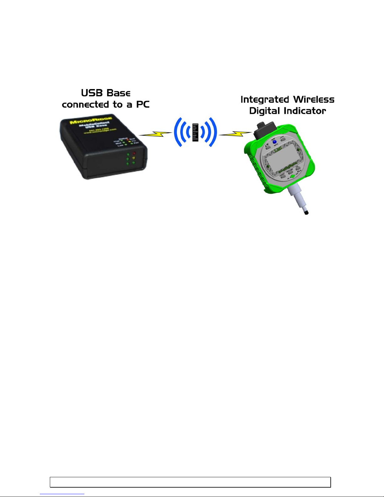
10.0 WIRELESS INDICATOR ADDENDUM
The LMI Wireless Digital Indicator can send readings to a PC via a MicroRidge Mobile Collect
USB Base unit . No add-on modules or cables are needed because the wireless is built directly into
the Diamondback Indicator.
In order to send readings the Wireless Diamondback needs to be associated to a specific Base Unit
connected to a PC.
STEPS TO ASSOCIATE TO A USB BASE:
1. Prior to association the MicroRidge Mobile Collect Setup Utility should be installed on the P C
and the base should be connected to the USB port. Refer to the Utility User Manual that came
with your base.
2. Open the Mobile Collect Setup Utility and select “Find Base” The base settings should
populate the data entry field.
3. In the utility Select the Mobile Module Setup Tab
4. On the indicator Press and Hold the “in/mm” button for 3 seconds to put the Diamondback into
setup mode. You will see “SEt UP” flash on the sc reen and the LEFT/RIGHT tolerance arrows
will continue to flash.
5. Once the Diamondback is in SETUP mode, press and release the “in/mm” button again to send
the indicator parameters to the base. You should see the data fields such as Module ID populate
in the utility.
6. In the wireless utility select the box “associate with Base unit connected to this setup program”
and press the “Send Setup to M obile Module” button in the lower right hand corner.
7. Press and Hold the “in/mm” butt on on the indicator for 3 seconds to exit the setup mode.
5 minutes of inactivity the unit will exit the setup mode automatically.
Unit should now be associated with the base and when the blue “SEND DATA” button is press ed
the reading is transmitted to the base. The LCD “DATA” icon appears in the upper right hand
corner of the LCD during transmission. If the base unit did not receive the reading correctly the
message “rF Err” will appear on the LCD.
The range o f wireless transmission is greatly affected by the environment in which the unit is used.
Average distance for good transmissions is approximately 100 feet.
The AAA Alkaline batteries that come with the unit are good for approximately 500,000 data
transmissions.
After
www.lmicorporation.com 20
 Loading...