

Page 1

Electronic Control “HPH-HPR-HPS”
User Manual
HP
EN
MC00005_04-EN - 01/2016
Firmware 3.1
True life inside
air and water
handling
for a confortable life
Page 2

HP User Manual
firmware 3.1 Rev.04 IT 2/ 51
Page 3

HP User Manual
firmware 3.1 Rev.04 IT 3/ 51
Summary
1 Control Features ................................................................................................................................................. 4
2 Wiring the remote terminal ................................................................................................................................ 5
3 User terminal ...................................................................................................................................................... 6
4 MENU DESCRIPTION ......................................................................................................................................... 10
PGD Menu ............................................................................................................................................................. 10
4.1. A. On/Off Unit ...................................................................................................................................... 11
4.2. B. Setpoint ........................................................................................................................................... 11
4.3. C. Clock/Scheduler ............................................................................................................................... 12
4.4. D. Input/Output ................................................................................................................................... 13
4.5. E. Data logger ...................................................................................................................................... 18
4.6. G. Service ............................................................................................................................................. 19
4.7. G.a. Change Language ................................................................................................................................ 19
4.8. G.b. Information ........................................................................................................................................ 19
4.9. G.c. Summer/Winter .................................................................................................................................. 20
4.10. G.d. Working hours ................................................................................................................................ 20
4.11. G.e. BMS config. ..................................................................................................................................... 21
4.12. G.f. Service setting ................................................................................................................................. 21
4.12.1. G.f.a. Working hours set......................................................................................................................... 21
4.12.2. G.f.b. Probe adjustment ......................................................................................................................... 22
4.12.3. G.f.c. Thermoregulation ......................................................................................................................... 24
4.12.4. G.f.d. User DEV/Change PW1 ................................................................................................................. 28
4.13. G.g.Manual management ....................................................................................................................... 28
4.14. H. Manufacturer .............................................................................................................................. 29
4.15. H.a. Configuration .................................................................................................................................. 29
4.16. H.b.I/O Configuration ............................................................................................................................. 31
4.17. H.c. Factory settings ............................................................................................................................... 33
4.18. H.d. Initialization .................................................................................................................................... 37
4.19. H.e. Input/Output Test ........................................................................................................................... 37
5 BMS USER VARIABLES ....................................................................................................................................... 38
6 ALARMS ............................................................................................................................................................ 47
NOTE ........................................................................................................................................................................ 51
Page 4

HP User Manual
firmware 3.1 Rev.04 IT 4/ 51
1 Control Features
Automatic selection
EC fans management
Management of the cooling circuit with inverter compressor
Management of the cooling circuit with inverter compressor
Reading pressure and temperature of the cooling circuit
Management of cooling unit defrost
Management of summer dehumidification
Manual ON-OFF
Cool/change over valve management
Defrost recovery management
Water coil anti-freeze management
ON-OFF electric heater management
Filter pressure switch management
Management of ventilation with CO2 probe
Management of ventilation with one or two pressure sensors
Free-cooling modulating management
Free-heating modulating management
Management of mixing chamber
Management of motorized dampers
Alarms management
Post ventilation
Weekly programming
Remote ON-OFF
Mode change (hot/cold) from digital input
Display on board machine
Remote display
Fixed point adjustment at flow
Adjustment of temperature and ambient humidity
BMS Modbus RS485 protocol
Page 5

HP User Manual
firmware 3.1 Rev.04 IT 5/ 51
2 Wiring the remote terminal
The remote terminal can be installed at max 50m using a 6 poles phone type cable.
Connect the terminal into the A connector of TCONN6J000
TCONN6J000 board
Wiring diagram for a distance up to 50 meters
pLAN setting with remote controller
When the display is ON press together the indicated buttons
Set “Display address setting” to 31 and press
When the display is ON press together the indicated buttons
Press twice
Set as shown the following screen
Then select “Ok?”, set “Yes” and press .
Now the matster board is configured
Display address
Setting..........: 21
I/O Board address: 01
Terminal config
Press ENTER
to continue
P:01 Adr Priv/Shared
Trm1 32 Sh
Trm2 21 Sh
Trm3 None -- Ok?No
max 50 m
Local terminal
Remote terminal
TCONN6J000
J14 and J15 on 2-3
alimentatore
power supply
20…30Vdc – 150mA
_
+
1 2 5
6
address 21
address 32
MASTER
SLAVE
address 1
address 2
Only size 144-205
Page 6

HP User Manual
firmware 3.1 Rev.04 IT 6/ 51
3 User terminal
Display PGD
The PGD1 is semi-graphic type with 8 rows per 22 columns with a 132x64 pixel resolution.
There are 6 buttons used to set the system:
PDG1
BUTTON
ALARM
See the active alarm list.
BUTTON PRG
Enter in main menu root.
BUTTON ESC
Back.
BUTTON UP
Scroll up or value increase.
On main screen, direct access to set-point menu.
BUTTON
DOWN
Scroll down or value decrease.
BUTTON
ENTER
Enter in the selected submenu or confirm setting.
+
BUTTON ESC
+
BUTTON UP
On main screen turn ON-OFF the unit.
+
BUTTON ESC
+
BUTTON
DOWN
Switch visualisation parameters circuit 1 or 2.
Display contrast setting
Press simultaneously + + and with the arrows set the contrast
Page 7

HP User Manual
firmware 3.1 Rev.04 IT 7/ 51
Home page
In the following image you can see the first page, showing mosto f the necessary information sto see the unit working mode.
On this windows you can see the working mode :
STATE UNIT
Unit off by
Alarm
Unit off by
Supervision
Unit off by
Scheduler
Unit off by
Digital input
Unit off by
keyboard
State mode unit
Manual Cold
Manual Hot
Auto Cold
Auto Hot
Defrost State
Heat recovery Defrost
Heat pump defrost
Clock
State Unit
Date
Page 8

HP User Manual
firmware 3.1 Rev.04 IT 8/ 51
Pressing down button you’ll access the the following page.
Electric Pre Heater State
Electric Post Heater State
Compressor State
Page 9

HP User Manual
firmware 3.1 Rev.04 IT 9/ 51
Pressing up button you’ll access the the following page.
This page is active when regulation probe is the supply air sensor
his page is active when regulation probe is the return air sensor
.
Page 10

HP User Manual
firmware 3.1 Rev.04 IT 10/ 51
To access these parameters, you must enter the
password PW2
4 MENU DESCRIPTION
PGD Menu
A. On/Off Unit
B. Setpoint
C. Clock/Scheduler
D. Input/Output
E. Data logger
G. Service
a. Change Language
b. Information
c. Summer / Winter
d. Working hours
e. BMS config.
f. Service settings
a. Working hour set
b. Probe adjustment
c. Thermoregulation
d. User DEV/Change PW1
g. Manual management
H. Manufacturer
a. Configuration
Compressor/Inverter
a. Configuration
b. Regolation
c. Custom
Driver EVD EVO o EVO
OnBoard
a. Configuration
b. Regolation
c. Custom
b. I/O Configuration
c. Factory settings
d. Initialization
e. Input/Output Test
To access these
parameters, you must
enter the password
PW1= 0010
Page 11

HP User Manual
firmware 3.1 Rev.04 IT 11/ 51
4.1. A. On/Off Unit
On the main menu (A.) you can set the unit state.
Or pressing the buttons Esc+UP from every first level menu.
+
TASTO ESC
+
TASTO SU
Premere contemporaneamente i tasti Esc+UP per accendere/spegnere l’unità.
4.2. B. Setpoint
The following figures shows the set-point screens .
Page active with regulation on return air sensor, automatic mode
Page active with regulation on return air sensor, manual mode
Page active with dehumidification active
Page active with air quality sensor active active
Page 12

HP User Manual
firmware 3.1 Rev.04 IT 12/ 51
4.3. C. Clock/Scheduler
Working mode:
The controller has an internal clock with a battery that preserve the clock operation.
Time and date setting and scheduler setting can be done on C.Clock/Scheduler menu. The related screen are:
Time and date setting;
Summer time enabling and setting;
Scheduler enabling;
Profile 1;
Profile 2;
Profile 3;
Profile enabling.
See the following screens:
Time and date setting
Summer time enabling and setting
Scheduler must be enable on the following screen:
Scheduler enabling
You can set on this screen 3 different set-points called profiles
Each profile includes the automatic and manual unit set-points and enabling of night fan speed reducing.
Once profiles have been defined you can set every half hour the required profile.
Page 13

HP User Manual
firmware 3.1 Rev.04 IT 13/ 51
On the screen you can:
select the day of the week
move on the timer ange and set the profile
copy the day schedule on an other day
None rectangle:
Status = OFF
Low rectangle:
Profile 1
Medium rectangle:
Profile 2
High rectagle:
Profile 3
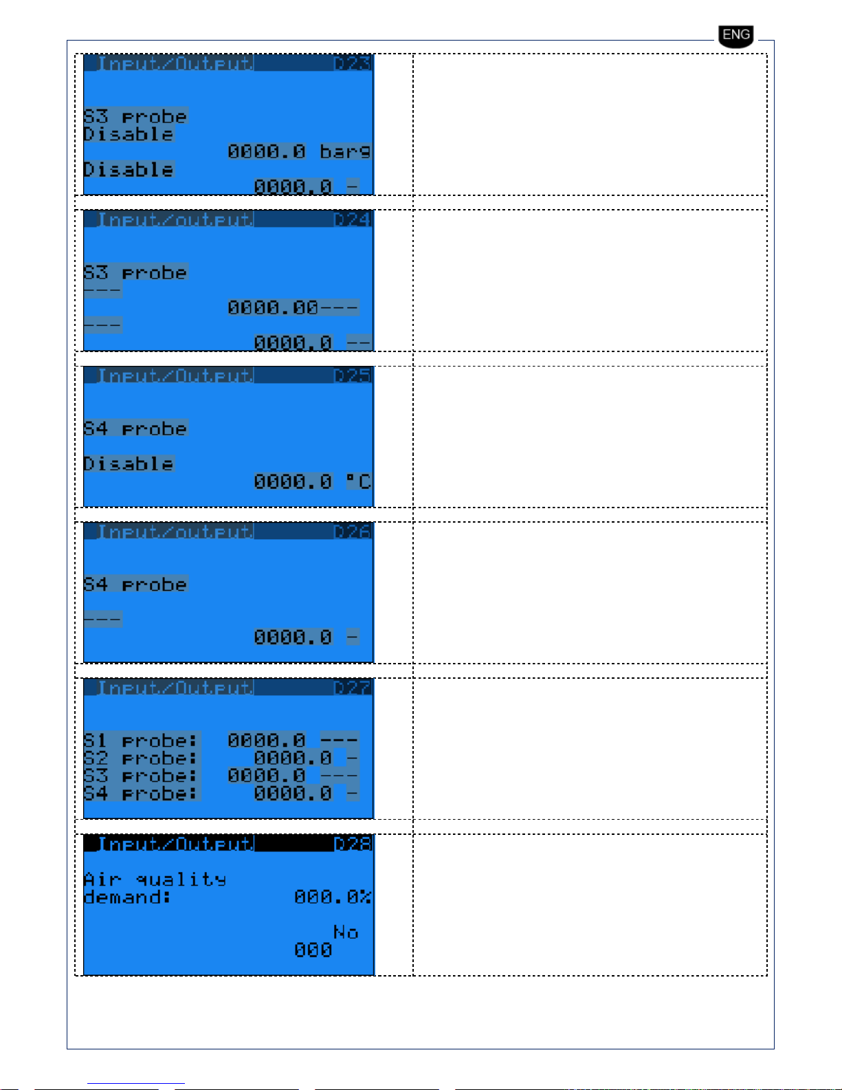
4.4. D. Input/Output
On this menu you can see the analog and digital input and output status. In case of not used I/O you’ll see “---“.
ID00 = Number of
digital input and
description
B00 = Number of
analog input and
description
Page 14

HP User Manual
firmware 3.1 Rev.04 IT 14/ 51
Compressor data screen
Heat pump data screen
Heat pump data screen
NO00 = Number of
digital output and
description
Page 15

HP User Manual
firmware 3.1 Rev.04 IT 15/ 51
Compressor data screen
EEV data screen
Compressor data screen
Compressor data screen
Compressor data screen
Compressor data screen
Page 16

HP User Manual
firmware 3.1 Rev.04 IT 16/ 51
Compressor data screen
Compressor data screen
Page 17
HP User Manual
firmware 3.1 Rev.04 IT 17/ 51
Page 18

HP User Manual
firmware 3.1 Rev.04 IT 18/ 51
4.5. E. Data logger
On this menu you can see the alarm history; to reset them you need to enter on service menu (password is needed).
Pressing the alarm button you can mute the buzzer, and see the active alarms and reset them (of course the alarm log will not be reset) and
then directly enter in the alarm history menu.
alarm date
alarm clock
alarm sequence number
Page 19

HP User Manual
firmware 3.1 Rev.04 IT 19/ 51
4.6. G. Service
This menu is divided inn sub-menu, the first four (a,b,c,d) are not password protected and allos you to set the following:
4.7. G.a. Change Language
Language set-up:
To exit press button
4.8. G.b. Information
you can find information about software code and version, and
installed electronic board .
Page 20

HP User Manual
firmware 3.1 Rev.04 IT 20/ 51
4.9. G.c. Summer/Winter
Automatic or manual season changeover.
4.10. G.d. Working hours
You can see the working hours of the main components installed on the
unit.
Page 21

HP User Manual
firmware 3.1 Rev.04 IT 21/ 51
Note: to access to the following sub-menu you need to enter the service password (PW1 ).
4.11. G.e. BMS config.
BMS setting: all the parameters necessary to set a BMS
communication.
4.12. G.f. Service setting
4.12.1. G.f.a. Working hours set
Working hour setting: it allows to set the maximum working hour of
unit main components that need a periodic maintenance.
On the same screen you can reset the worked hours of each
component.
Page 22

HP User Manual
firmware 3.1 Rev.04 IT 22/ 51
4.12.2. G.f.b. Probe adjustment
Sensors calibration: you can set an offset to add or remove on each
sensor reading. Once confirmed the sensor value is automatically
updated (reported on side).
Page 23

HP User Manual
firmware 3.1 Rev.04 IT 23/ 51
Page 24

HP User Manual
firmware 3.1 Rev.04 IT 24/ 51
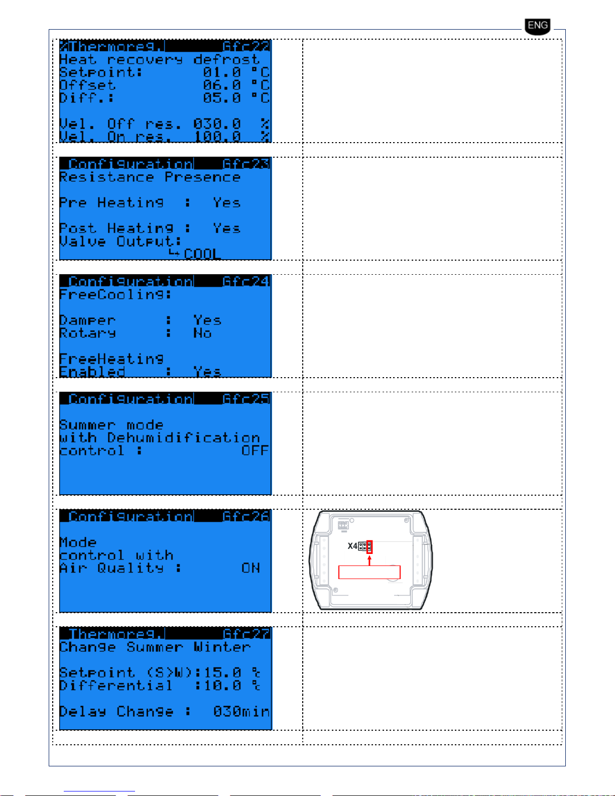
4.12.3. G.f.c. Thermoregulation
Setting of thermoregulation.
Screen active with free-cooling active
Page 25

HP User Manual
firmware 3.1 Rev.04 IT 25/ 51
Screen active with free-cooling active
Screen active with free-heating active
Screen active with free-heating active
Page 26
HP User Manual
firmware 3.1 Rev.04 IT 26/ 51
R1
R2
R3
QPM2100
QPM2100
remove jumper
QPM2100
remove jumper R3
R3 jumper open= 0-5V
R3 jumper close= 0-10V
Page 27

HP User Manual
firmware 3.1 Rev.04 IT 27/ 51
Set (%)costant flow pressur sensor:
Taglia
014
020
026 k
60
95
121
Taglia
050
092
144
205 k
121
197
308
394
Page 28

HP User Manual
firmware 3.1 Rev.04 IT 28/ 51
4.12.4. G.f.d. User DEV/Change PW1
User DEV/Change PW1: you can reset the alarm history and change the
password PW1.
4.13. G.g.Manual management
Page 29

HP User Manual
firmware 3.1 Rev.04 IT 29/ 51
4.14. H. Manufacturer
To access to this menu you need the manufacturer password (PW2 ):
4.15. H.a. Configuration
Configuration: you can select the main features of the unit and the operation of each component.
On the following screens you can see the features of the installed components and the hardware seting.
You can also see the EEV driver setting (a.Configuration, b.Regolation, c.Custom ) and of the compressor / driver (a.Configuration,
b.Regolation, c.Custom).
These parameters are related to the serial port of the compressor
driver.
Page 30

HP User Manual
firmware 3.1 Rev.04 IT 30/ 51
These parameters are related to the serial port of the compressor
driver.
Page 31

HP User Manual
firmware 3.1 Rev.04 IT 31/ 51
4.16. H.b.I/O Configuration
I/O Configuration
On this menu you can activate and set each I/O.
Page 32

HP User Manual
firmware 3.1 Rev.04 IT 32/ 51
Page 33

HP User Manual
firmware 3.1 Rev.04 IT 33/ 51
4.17. H.c. Factory settings
Factory setting: the following screens allows the set all the manufacturer reserved parameter.
Page 34

HP User Manual
firmware 3.1 Rev.04 IT 34/ 51
Page 35

HP User Manual
firmware 3.1 Rev.04 IT 35/ 51
Page 36

HP User Manual
firmware 3.1 Rev.04 IT 36/ 51
Page 37

HP User Manual
firmware 3.1 Rev.04 IT 37/ 51
4.18. H.d. Initialization
Default installation: complete reset of the default value.
On this screen you can change the manufacture value.
4.19. H.e. Input/Output Test
Page 38
HP User Manual
firmware 3.1 Rev.04 IT 38/ 51
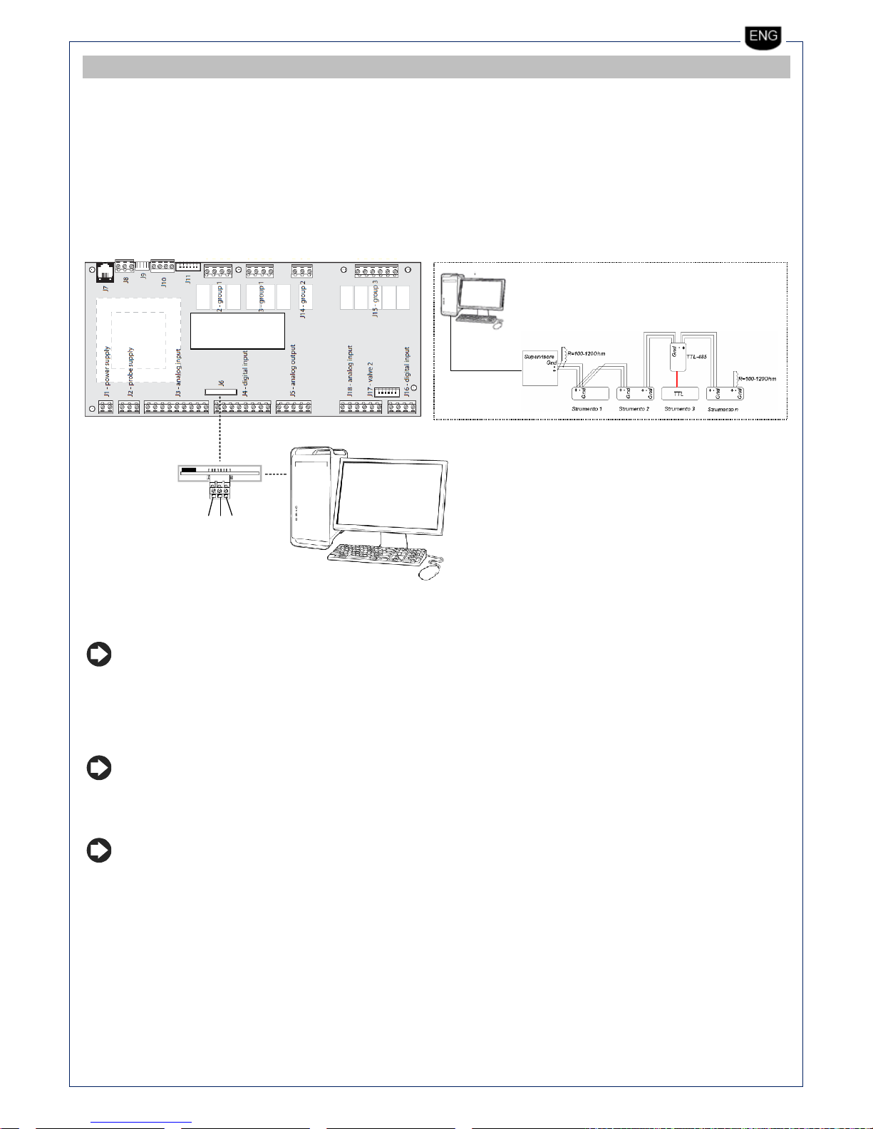
5 BMS USER VARIABLES
The unit can be connected the several supervision system, in particular the following BMS protocols can be used:
Carel and Modbus.
The connection is made by a BMS serial port.
The connetion protocol is managed by the following optional board:
Modbus RS485: cod. PCOS004850 (see Fig. 8.a)
On the following figure you can see the connection diagram between BMS and uPC.
120ohm
MASTER
GND
RX/TX +
RX/TX -
Fig. 8.a
Note:
Suggested cable for data line with 100-120ohm impedance type BELDEN 3105A EIA Industrial RS-485 PLTC/CM
The following table shows the variables shared with supervisor.
Nota: On the first column shows the Carel address, the second one the ModBus address (packet), in case of
“register” communication mode, the address of the ModBus column must be increased of 1, both for digital variable
(coil) and for analog variable (register).
Nota: (*) “nome” indica il nome della variabile utilizzato internamente per il programma di commissionino
Page 39

HP User Manual
firmware 3.1 Rev.04 IT 39/ 51
CAREL
MODBUS
COIL (1)-Digital/MODBUS
TAG NAME
TAG DESCRIPTION
1
2
DIGITAL INPUT 1
din1_msk
Status of digital input (0=Closed;
1=Open) 2 3
DIGITAL INPUT 2
din2_msk
Status of digital input (0=Closed;
1=Open) 3 4
DIGITAL INPUT 3
din3_msk
Status of digital input (0=Closed;
1=Open) 4 5
DIGITAL INPUT 4
din4_msk
Status of digital input (0=Closed;
1=Open) 5 6
DIGITAL INPUT 5
din5_msk
Status of digital input (0=Closed;
1=Open)
6
7
DIGITAL INPUT 6
din6_msk
Status of digital input (0=Closed;
1=Open)
7
8
DIGITAL INPUT 7
din7_msk
Status of digital input (0=Closed;
1=Open)
8
9
DIGITAL INPUT 8
Din8_msk
Status of digital input (0=Closed;
1=Open)
9
10
DIGITAL INPUT 9
Din9_msk
Status of digital input (0=Closed;
1=Open)
10
11
DIGITAL INPUT 10
Din10_msk
Status of digital input (0=Closed;
1=Open)
11
12
12
13
13
14
14
15
15
16
16
17
17
18
18
19
19
20
20
21
DIGITAL OUTPUT 1
Dout1_Value
(0-Open;1-Close)
21
22
DIGITAL OUTPUT 2
Dout2_Value
(0-Open;1-Close)
22
23
DIGITAL OUTPUT 3
Dout3_Value
(0-Open;1-Close)
23
24
DIGITAL OUTPUT 4
Dout4_Value
(0-Open;1-Close)
24
25
DIGITAL OUTPUT 5
Dout5_Value
(0-Open;1-Close)
25
26
DIGITAL OUTPUT 6
Dout6_Value
(0-Open;1-Close)
26
27
DIGITAL OUTPUT 7
Dout7_Value
(0-Open;1-Close)
27
28
DIGITAL OUTPUT 8
Dout8_Value
(0-Open;1-Close)
28
29
DIGITAL OUTPUT 9
Dout9_Value
(0-Open;1-Close)
29
30
DIGITAL OUTPUT 10
Dout10_Value
(0-Open;1-Close)
30
31
DIGITAL OUTPUT 11
Dout11_Value
(0-Open;1-Close)
31
32
DIGITAL OUTPUT 12
Dout12_Value
(0-Open;1-Close)
32
33
33
34
34
35
35
36
36
37
37
38
38
39
39
40
40
41
Summer-winter working mode
Summer -Winter
Status (0: Summer; 1: Winter)
41
42
BMS On/Off
Off-On
Status (0: Off; 1: On)
100
101
101
102
A001 Clock board error
Page 40

HP User Manual
firmware 3.1 Rev.04 IT 40/ 51
102
103
A002 Extend memory error
103
104
A003 Compressor start-up failed
104
105
A004 Envelope zone alarm:
105
106
A005 High compressor discharging temperature
106
107
A006 Low pressure difference
107
108
A007 Inverter type not compatible
108
109
A008 Power+ Device Offline
109
110
A009 Power+ see “Inverter erros list”
110
111
A010 S1 sensor failure
Low pressure
111
112
A011 S2 sensor failure
Compressor Suction Temp.
112
113
A012 S3 sensor failure
High pressure
113
114
A013 S4 sensor failure
Compressor discharge Temp.
114
115
A014 (LowSH) Low overhetaing
115
116
A015 (LowSH) Low overheting
116
117
A016 (LOP) Low evaporation temperature
117
118
A017 (LOP) Low evaporation temperature
118
119
A018 (MOP) High evaporation temperature
119
120
A019 (MOP) High evaporation temperature
120
121
A020 High condensing temperature
121
122
A021 Low condensing temperature
122
123
A022 Low suction temperature
123
124
A023 Autotune Valve A-
124
125
A024 Autotune Valve B-
125
126
NOT USED
NOT USED
126
127
NOT USED
NOT USED
127
128
A027 High Pressure Alarm Compressor 1
128
129
A028 Low Pressure Allarm Compressor 1
129
130
A029 Disabled Compressor Start DP
130
131
A030 Air Flow Switch (ID)
131
132
A031 Fan Alarm (ID)
132
133
A032 Filter Pressure Switch Supply/Return (ID)
133
134
A033 High Pressure Alarm Compressor 1 (ID)
134
135
A034 Mix room alarm
135
136
A035 B1 sensor failure
Exhaust temp.
136
137
A036 B2 sensor failure
Fresh air temp.
137
138
A037 B12 sensor failure
Air quality sensor
138
139
A038 NOT USED
NOT USED
139
140
A039 NOT USED
NOT USED 140
141
A040 Door Micro switch Alarm
141
142
A041 High Pressure Prevention Function
142
143
A042 B8 sensor failure
Saturation Temp.
143
144
A043 B9 sensor failure
Return Temp.
144
145
A044 B10 sensor failure
Return humidity
145
146
A045 Circuit 2 Offline
146
147
A046 Circuit 1 Offline
147
148
A047 Circuit 1 Alarm
148
149
A048 Circuit 2 Alarm
149
150
A049 B3 sensor failure
Supply temp.
Page 41

HP User Manual
firmware 3.1 Rev.04 IT 41/ 51
150
151
A050 Electric Heating Thermal protection
199
200
200
201
201
202
Comp_On_1
Compressor power on
202
203
Comp_Request_Env
Request to switch on/off compressor
from envelope
203
204
204
205
205
206
206
207
207
208
208
209
209
210
210
211
211
212
212
213
En_Inverter
EnablePower + Inverter
213
214
214
215
215
216
216
217
217
218
218
219
219
220
CAREL
MODBUS
INPUT (2)- Analog/MODBUS
TAG NAME
TAG DESCRIPTION
1
2
ANALOG INPUT VALUE 1
Ain1_Std_UM
Exhaust temp. 2 3
ANALOG INPUT VALUE 2
Ain2_Std_UM
Fresh air temp. 3 4
ANALOG INPUT VALUE 3
Ain3_Std_UM
Supply air temp. 4 5
ANALOG INPUT VALUE 4
Ain4_Std_UM
Compressor 1 suction temp.
5
6
ANALOG INPUT VALUE 5
Ain5_Std_UM
Compressor 1 discharge temp.
6
7
ANALOG INPUT VALUE 6
Ain6_Std_UM
C1 high pressure transducer
7
8
ANALOG INPUT VALUE 7
Ain7_Std_UM
C1 low pressure transducer
8
9
ANALOG INPUT VALUE 8
Ain8_Std_UM
Saturation temp.
9
10
ANALOG INPUT VALUE 9
Ain9_Std_UM
Return air temp.
10
11
ANALOG INPUT VALUE 10
Ain10_Std_UM
Return air humidity
11
12
ANALOG INPUT VALUE 11
Ain11_Std_UM
12
13
ANALOG INPUT VALUE 12
Ain12_Std_UM
Air quality sensor
13
14
ANALOG OUTPUT Y1
Supply fan
14
15
ANALOG OUTPUT Y2
Return fan
15
16
ANALOG OUTPUT Y3
Water valve
16
17
ANALOG OUTPUT Y4
By-pass modulating damper
17
18
18
19
19
20
20
21
RoomSet_Heat
Room PI regulheatig setpoint
21
22
RoomSet_Cool
Room PI regul cooling setpoint
22
23
RoomSetP_Operative
23
24
Calculated Set point
DelivAirSetP_Temp
Delivery air setpoint (calculated)
Page 42

HP User Manual
firmware 3.1 Rev.04 IT 42/ 51
24
25
25
26
ANALOG INPUT VALUE 4 SLAVE
Compressor 2 suction temp.
26
27
ANALOG INPUT VALUE 5 SLAVE
Compressor 2 discharge temp.
27
28
ANALOG INPUT VALUE 6 SLAVE
C2 high pressure transducer
28
29
ANALOG INPUT VALUE 7 SLAVE
C2 low pressure transducer
29
30
30
31
31
32
32
33
33
34
34
35
35
36
36
37
37
38
38
39
39
40
40
41
Return air Set-point (automatic mode)
RoomSetP
Room setpoint
41
42
Return air Set-point (summer)
RoomSetP_Summer
42
43
Return air set-point (winter)
RoomSetP_Winter
43
44
Neutral zone
RoomDeadBand
200
201
201
202
Rotor_Speed_Hz
202
203
Rotor_Speed_rps_1
Compressor rotor speed rps [1/10rps]
203
204
Maximum_output_freq
uency_Rps
Maximum power+ output frequency set
(Rps)
204
205
Minimum_output_freq
uency_Rps
Minimum drive output frequency (rps)
205
206
Motor_Current
Motor current [1/10 A]
206
207
Inverter_Req_0_1000
Speed request to inverter (filtered by
envelop) 0-1000 [1/10%]
207
208
A100_DISCHARGE_SH_
SET_1
SetPoint of Discharge SH (EE Valve
subregulation) [1/10°C]
208
209
A101_DISCHARGE_TEM
P_SET_1
SetPoint of Discharge Temp (EE Valve
subregulation) [1/10°C]
209
210
MOP_Inhibition_Thr_1
to EVD Pin of MOP inhibition threshold
210
211
A107_MOP_THRESHOL
D_FAST_CHANGE_1
211
212
A106_S4_NTC_THERM
AL_TIME_K_1
212
213
Evap_Reg_Setpt_T_1
Evaporating temp. limit Setpoint (Fan
regul. in Pdc) [1/10°C]
213
214
Evap_Reg_Setpt_P_1
Evaporating press.limit Setpoint (Fan
regul. in Pdc) (1/10bar]
214
215
Cond_Reg_Setpt_P_1
Condensing press. limit Setpoint (Fan
regul. in chiller) [1/10bar]
215
216
Cond_Reg_Setpt_T_1
Condensing temp. limit Setpoint (Fan
regul. in chiller) [1/10°C]
216
217
217
218
218
219
219
220
220
221
300
301
301
302
Suction_Temp_A1
Suction temperature - EE valve [1/10°C]
Page 43

HP User Manual
firmware 3.1 Rev.04 IT 43/ 51
302
303
Evaporation_Temp_A1
Evaporation temperature - EE valve
[1/10°C]
303
304
Evaporation_Press_A1
Evaporation pressure valve A
304
305
Superheat_A1
Superheat - EE valve [1/10°C]
305
306
Condensing_Press1
Condensing pressure
306
307
Condensing_Temp1
Condensing temperature - EE Valve
[1/10°C]
307
308
A104_DISCHARGE_SH1
308
309
Tdischarge_Gas_EVO
Discharge gas temperature with EVD
[1/10°C]
309
310
310
311
311
312
A10_SH_SH
Superheat valve A
312
313
A5_SH_SUCT_TEMP
Suction temperature valve A
313
314
314
315
A17_EEV_POSITION_PE
RCENT_SHOW
315
316
316
317
A7_SH_EVAP_PRES
Evaporation pressure valve A
317
318
A6_SH_EVAP_TEMP
Evaporation temperature valve A
318
319
319
320
320
321
321
322
322
323
323
324
324
325
325
326
326
327
327
328
328
329
CAREL
MODBUS
INTEGER (3)-
INTEGER/MODBUS
TAG NAME
TAG DESCRIPTION
1
5003
Unit_Status
{;Unit'ON;OFFbyALR;OFFbyNET;OFFbyBMS;OFFbyFSC;OF
FbyDIN;OFFbyKEY;;OFF_CST1;OFF_CST2;OFF_CST3;OFF_
CST4;}
2
5004
3
5005
4
5006
5
5007
6
5008
7
5009
8
5010
9
5011
10
5012
SetSpeedExhaustFan
Set Speed of exhaust fan (FAN1)
11
5013
SetSpeedSupplyFan
Set speed of supply fan (FAN2)
12
5014
AOut3 ( Valvola Acqua )
Analogic Output Y3 value
13
5015
14
5016
15
5017
16
5018
17
5019
Page 44

HP User Manual
firmware 3.1 Rev.04 IT 44/ 51
18
5020
19
5021
20
5022
100
5102
101
5103
102
5104
103
5105
104
5106
Envelope_Zone_1
Envelopeworking zone:
0=Null;1=OK;2=Max.comp.R.;3=Max.disch.P.;4=HCurr.;5
=Max.suct.P.;6=Min.comp.R.;7=LowDP;8=Min.disch.P.;9=
Min.suct.P.
105
5107
106
5108
107
5109
108
5110
Inv_PowerPlus_Device_Number
Progressive device nr. in the system
109
5111
Current_error_code_1
Inverter error code: 0: No fault;1: Overcurrent;2: Motor
overload;3: Overvoltage;4: Undervoltage;5: Drive
overT.;6: Drive underT;7: Overcurrent HW;8: Motor
overtemp.;9: Reserved;10: Cpu error;11: Param.
default;12: DC bus ripple;13: Data comms fault;14: Drive
thermistor;15: Autotune fault;16: Drive disabled;17:
Motor phase;18: Fan fault;19: Speed fault
110
5112
111
5113
112
5114
113
5115
114
5116
115
5117
116
5118
117
5119
118
5120
119
5121
120
5122
121
5123
122
5124
123
5125
124
5126
125
5127
Alarm_Code_EBM1
126
5128
Alarm_Code_EBM2
127
5129
128
5130
129
5131
130
5132
131
5133
132
5134
133
5135
134
5136
135
5137
136
5138
137
5139
138
5140
Page 45

HP User Manual
firmware 3.1 Rev.04 IT 45/ 51
139
5141
140
5142
200
5202
201
5203
Rotor_Speed_0_1000
Compressorrotorspeed 0-1000
202
5204
Rotor_Speed_rpm
Compressorrotorspeed [rpm]
203
5205
Drive_Status
Show the inverter status: 0 = Stopped 1= run 2 = alarm
204
5206
Motor_Voltage
Motor Voltage [V- Integer]
205
5207
Drive_Temp
Inverter Temperature [°C]
206
5208
DC_Bus_Voltage
DC Bus Voltage [V]
207
5209
Current_error_code_1
Inverter error code: 0: No fault;1: Overcurrent;2: Motor
overload;3: Overvoltage;4: Undervoltage;5: Drive
overT.;6: Drive underT;7: Overcurrent HW;8: Motor
overtemp.;9: Reserved;10: Cpu error;11: Param.
default;12: DC bus ripple;13: Data comms fault;14: Drive
thermistor;15: Autotune fault;16: Drive disabled;17:
Motor phase;18: Fan fault;19: Speed fault
208
5210
Refrigerant_1
Gas type - Valve A
209
5211
Circuit_Cooling_Capacity_Env_A
Actual circuit cooling capacity for EVD valve from
envelope
210
5212
I89_REGULATION_SUB_TYPE_1
regulationsubtipe
211
5213
Env_Countdown_1
Countdown of out of envelop alarm [s]
212
5214
Envelope_Zone_1
Envelopeworking zone: 0=Null; 1=OK; 2=Max.comp.R.;
3=Max.disch.P.; 4=HCurr.; 5=Max.suct.P.;
6=Min.comp.R.; 7=LowDP; 8=Min.disch.P.; 9=Min.suct.P.
213
5215
Disch_Temp_Zone_1
Discharge temperature zone: 0 = null; 1= OK; 2 =
Controlled; 3 = Limited
214
5216
215
5217
216
5218
217
5219
218
5220
219
5221
220
5222
221
5223
Motor_Type
0=Custom; 1=Siam ANB33F-400V; 2=Siam ANB42F400V;3=Siam ANB52F-400V;4=Samsung UG5T520F-400V
222
5224
223
5225
224
5226
225
5227
226
5228
227
5229
228
5230
229
5231
230
5232
300
5302
301
5303
LP_cents_EVO_high_precision
Low pressure: cents of Bar
302
5304
HP_cents_EVO_high_precision
High pressure cents of Bar
303
5305
I4_EEV_POSITION_STEPS
Position valve A
304
5306
I8_REG_STATUS
EVD Evolution OnBoard regulation status valve A
305
5307
306
5308
307
5309
Page 46

HP User Manual
firmware 3.1 Rev.04 IT 46/ 51
308
5310
309
5311
310
5312
Page 47

HP User Manual
firmware 3.1 Rev.04 IT 47/ 51
6 ALARMS
When Alarm button is blinking an alarm is active. Pressing the button you directly acces to the active alarm list.
Note: Two alarm need to be manually reset (inverter and doors micro switch), to reset them keep pressed the Alarm button, once done
the system automatically switches to the home page.
N° ALARM end DESCRIPTION
CHECK TO BE DONE
A001 Clock board error
Replace the button battery (CR2430 3V type)
A002 Extend memory error
Replace main PCB
A003 Compressor start-up failed (Check motor connection)(tent.: /
max.: )
Check compressor motor wiring (follow the electric wiring diagram
supplied with the unit)
A004 Envelope alarm Zone:1,2,3,4,5,6,7,8,9 see “Envelope Alarm
list”
Contact service dept
A005 High compressor discharging temperature
Contact service dept
A006 Low pressure difference (poor lubrication.)
Contact service dept
A007 Inverter type not compatible (only type Power+)
Contact service dept
A008 Power+ n° Device Offline
Check compressor driver power supply and wiring
A009 Power+ n° see “Inverter error list”
Contact service dept
A010 S1 sensor failure (Low pressure)
Check wiring and sensor type (SPKT0043R0 0-17,3bar)
A011 S2 sensor failure (Compressor Suction Temp.)
Check wiring and sensor type (NTC030WF00)
A012 S3 sensor failure (High pressure)
Check wiring and sensor type (SPKT00B6R0 0-44,8bar)
A013 S4 sensor failure (Compressor discharge Temp.)
Check wiring and sensor type (NTC030HTF00)
A014 (LowSH) Low overheating valve A-
Contact service dept
A015 (LowSH) Low overheating valve B-
NOT USED
A016 (LOP) Low evaporation temperature valve A-
Contact service dept
A017 (LOP) Low evaporation temperature valve B-
NOT USED
A018 (MOP) High evaporation temperature valve A-
Contact service dept
A019(MOP) High evaporation temperature valve B-
NOT USED
A020 High condensing temperature (HiTCond)
Contact service dept
A021 Low suction temperature valve A-
Contact service dept
A022 Low suction temperature valve B-
NOT USED
A023 Autotune Valve A-
Contact service dept
A024 Autotune Valve B-
NOT USED
A025 NOT USED
NOT USED
A026 NOT USED
NOT USED
A027 High Pressure Alarm Compressor 1
1) Summer mode: exhaust airflow too low
a. exhaust fan speed too low
b. dirty filters or clogged ductwork
c. air conditions over limit
2) Winter mode: supply airflow rate too low
a. supply fan speed too low
b. dirty filters or clogged ductwork
3) Freon filling too high
A028 Low Pressure Alarm Compressor 1
1) Summer mode: supply airflow too low
a. supply fan speed too low
b. dirty filters or clogged ductwork
Page 48

HP User Manual
firmware 3.1 Rev.04 IT 48/ 51
c. outside air conditions over limit
2) Winter mode: exhaust airflow too low
a. exhaust fan speed too low
b. dirty filters or clogged ductwork
c. air conditions over limit
3) Freon filling insufficient
A029 Disabled Compressor Start DP
Contact service dept
A030 Air Flow Switch (DI)
Check digital input DI4
A031 Fan Alarm (DI)
Check fan fuses or replace fans
A032 Filter Pressure Switch Supply/Return (DI)
Clean or replace air filter
A033 High Pressure Alarm Compressor 1 (DI)
Check digital input DI6
A034 Mix box alarm
Additional PCB SMD4500 failure (managing mixing box and modulating
electric pre-heater)
A035 B1 sensor failure (Exhaust temp.)
Check sensor wiring or replace it (NTC10k 25°C)
A036 B2 sensor failure (Fresh air temp.)
Check sensor wiring or replace it (NTC10k 25°C)
A037 B12 sensor failure (Air quality sensor)
Check sensor wiring or replace it (2000ppm 0-5V)
A038 NOT USED
NOT USED
A039 NOT USED
NOT USED
A040 Door Micro switch Alarm
Check digital input DI5
A041 High Pressure Prevention Function
Reduced operation mode warning.
1) Summer mode: bassa exhaust airflow too low
a. exhaust airflow too low
b. dirty filters or clogged ductwork
c. air conditions over limit
2) Winter mode: supply airflow too low
a. supply fan speed too low
b. dirty filters or clogged ductwork
c. air conditions over limit
4) Freon filling too high
A042 B8 sensor failure (Saturation Temp.)
Check sensor wiring or replace it (NTC10k 25°C)
A043 B9 sensor failure (Return Temp.)
Check sensor wiring or replace it (NTC10k 25°C)
A044 B10 sensor failure (Return humidity)
Check sensor wiring or replace it (0-100% 4-20mA)
A045 Circuit 2 Offline
Check compressor driver & main PCB Modbus connection
A046 Circuit 1 Offline
Check compressor driver & main PCB Modbus connection
A047 Circuit 1 Alarm
Alarm conditions on circuit 1 while visualizing circuit 2.
.
Select circuit 1 by keys +
A048 Circuit 2 Alarm
Alarm conditions on circuit 2 while visualizing circuit 1.
Select circuit 2 by keys +
A049 B3 sensor failure (Supply temp.)
Check sensor wiring or replace it (NTC10k 25°C)
A050 Electric Heating Thermal protection
Insufficient airflow rate
Page 49

HP User Manual
firmware 3.1 Rev.04 IT 49/ 51
“ENVELOPE ERROR”
1: Inside envelope
2: High compression ratio
3: High condensing pressure
4: High current
5: High evaporation pressure
6: Low compression ratio
7: Low pressure difference
8: Low condensing pressure
9: Low evaporating pressure
“ENVELOPE ERROR”
1: Over current
2: Motor over current
3: High voltage
4: Low voltage
5: High temperature
6: Low temperature
7: HW overcurrent
8: Motor High temperature
9: Drive fault
10: Cpu error
11: Default parameters
12: DC bus ondulation
13: timeout com.ser.
14: Thermistor error
15: Autotuning error
16: Drive disabled
17: Motor missing phase
18: Fan fault
19: Motor stalemate
20: PFC module fault
21: Alarm code 21
22: PFC low voltage
23: STO reading error
24: STO reading error
25: Alarm code 25
26: Alarm code 26
27: Alarm code 27
28: Alarm code 28
29: Alarm code 29
30: Alarm code 30
…. 99: Unexpected inverter stop
Page 50

HP User Manual
firmware 3.1 Rev.04 IT 50/ 51
HPR-H-S
14
20
26
50
92
144
205
k x Fan
N° Fan 1 1 1 1 1 2 2
RH25C
60
60
RH31C 95 95
GR35C
121
121 121
GR40C 308 154
GR45C
197 394
197
Air flow m³/h (V) MAX HPR-H
1200
2100
2900
5700
9500
13500
19000
HPR-H
Air flow m³/h (V) MAX HPS
1200
2100
2600
4800
7700
11400
13200
HPS
Air flow m³/h (V) Min HPR-H
360
630
870
1710
2850
4050
5700
HPR-H
Air flow m³/h (V) Min HPS
360
630
780
1440
2310
3420
3960
HPS
Set DP (Pa) MAX HPR-H
400
489
574
2219
2325
1921
2325
DP (Pa)= (V/k)²
Set DP (Pa) MAX HPS
400
489
462
1574
1528
1370
1122
Set DP (Pa) Min HPR-H
36
44
52
200
209
173
209
DP (Pa)= (V/k)²
Set DP (Pa) Min HPS
36
44
42
142
137
123
101
FSS Pressure sensor range (Pa)
1000
1000
1000
5000
5000
5000
5000
Signal % 0-10V MAX HPR-H
40
49
57
44
47
38
47
%= (Set/FSS)*100
Signal % 0-10V MAX HPS
40
49
46
31
31
27
22
Signal % 0-10V Min HPR-H
10.0
10.0
10.0
10.0
10.0
10.0
10.0
All
Signal % 0-10V Min HPS
10.0
10.0
10.0
10.0
10.0
10.0
10.0
Set= 10% (1.0V)
Signal % 0 10 =
()
× 100
Page 51

HP User Manual
firmware 3.1 Rev.04 IT 51/ 51
NOTE
__________________________________________________________
__________________________________________________________
__________________________________________________________
__________________________________________________________
__________________________________________________________
__________________________________________________________
__________________________________________________________
__________________________________________________________
__________________________________________________________
__________________________________________________________
__________________________________________________________
__________________________________________________________
__________________________________________________________
__________________________________________________________
__________________________________________________________
__________________________________________________________
__________________________________________________________
__________________________________________________________
__________________________________________________________
__________________________________________________________
__________________________________________________________
__________________________________________________________
__________________________________________________________
__________________________________________________________
__________________________________________________________
__________________________________________________________
__________________________________________________________
__________________________________________________________
__________________________________________________________
__________________________________________________________
 Loading...