

Page 1
Gujarat Madhya Pradesh: 1800-2582-583 | Punjab,Haryana,Himachal Pradesh, J&K:1800-1377-781|
Maharashtra,Chattisgarh,Goa:1800-1024-212 | South India: 1800-1200-666 | Rest of India : 1800-1020-666
Page 2

Congratulations on being the proud owner of Lloyd Air
Conditioner. Your Air Conditioner comes with Lloyd
Guarantee of Quality.
Lloyd takes great pride in
Dear Customer
Page 3
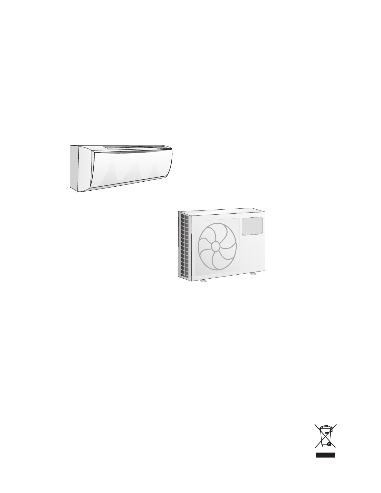
Thank you for choosing our Air Conditioner. Please read this INSTALLATION
HANDBOOK carefully prior to installing and keep it for further reference.
Incorrect behaviour may cause fire, electric shock and the unit falling may result in
injury or water leakage. Contact our designated air conditioner service centre and
specialists. The manufacturer shall not assume responsibility for accidents or injury
caused by incorrect behaviour.
SPLIT WALL MOUNTED TYPE
INSTALLATION HANDBOOK
AIR CONDITIONERS
This product must not be disposed together with the domestic waste.
This product has to be disposed at an authorized place for recycling
of electrical and electronic appliances.
Do not attempt to install, maintain the Air Conditioner by yourself.
Page 4
1
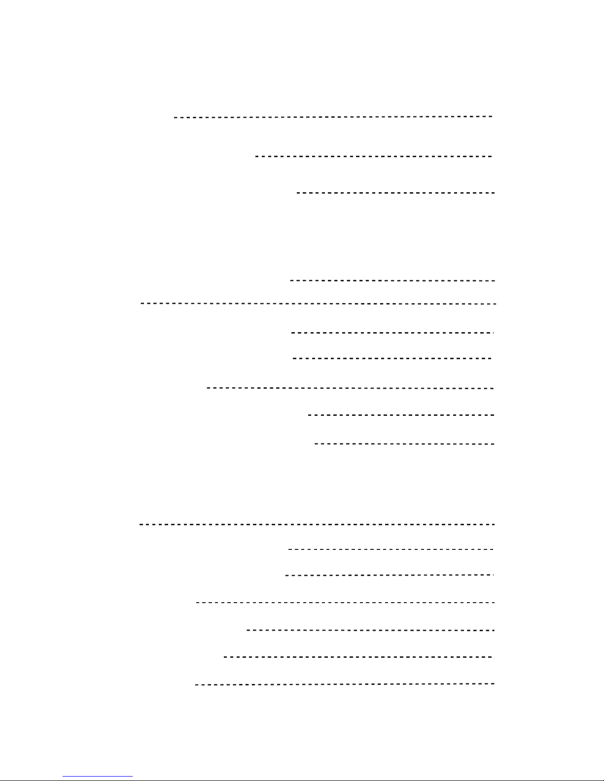
CONTENTS
2
3
3
4
1
Contents
Installation of the indoor unit
Securing the mounting plate
Wiring
Installation sketch
Installation instructions
4
5
Installation of the drain hose
Installation of the indoor unit
5
5
Pipe connection
Arrangement of the drain hose
5
Wall sealing and Pipe fastening
6
9
Installation of the outdoor unit
Wiring
Installation of the drain joint
9
9
Joint of the connecting pipe
Air exhausting
9
10
Process of flared tube
Adding refrigerant
10
Operation test
Page 5
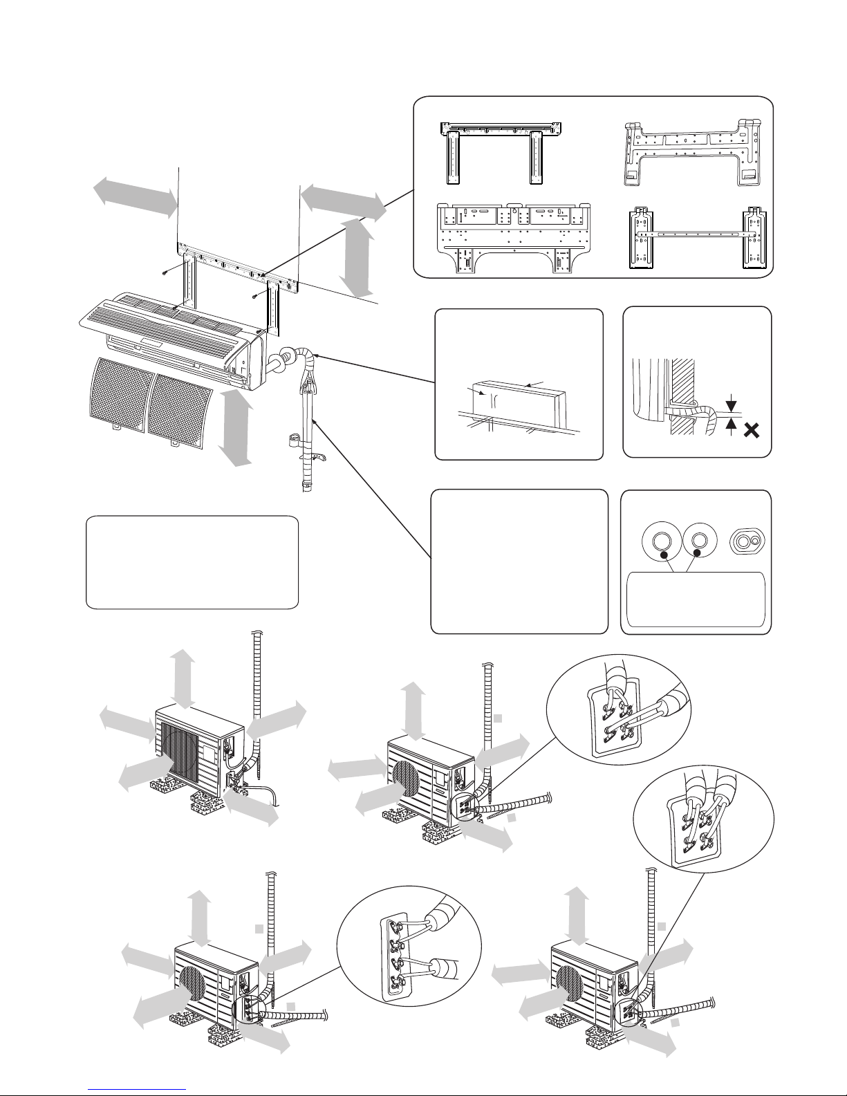
front
right
back
underside
left-back
back
Notice: do not raise the
drain hose.
The connecting pipe can be led
from back, right, underside,
or left-back side.
Cover connecting pipe with
adiabatic material.
Sponge plastic adiabatic
material with the
thickness of 8mm.
While installing the pipeline on the
thin armor plate or on the wall of
metal mesh, you should use the
wooden board to clamp between
the wall and the pipeline, or wrap
up the pipeline with 7-8 layers of
insulating plastic tape.
left
INSTALLATION SKETCH
2
Confirm the installation position by the mark of the indoor mounting plate.
or
or or
above 155mm
above 250mm
Above 20mm
above 105mm
100mm以上
above 300mm
above 500mm
above 300mm
above 500mm
above 500mm
Single Split Model
OR
A
B
T
O INDOOR UNIT
above 500mm
above 300mm
above 300mm
Above 500mm
above 500mm
T
O INDOOR UNIT
Dual Split Model
B
TO INDOOR UNIT
A
above 300mm
above 500mm
above 300mm
above 500mm
above 500mm
A
B
A
B
A
B
T
O INDOOR UNIT
above 500mm
above 300mm
above 300mm
above 500mm
Above 500mm
T
O INDOOR UNIT
Dual inverter Model
A
B
TO INDOOR UNIT
Attention:
The allowable length of the connecting
pipe is 10m.
The allowable distance between indoor
unit and outdoor unit is 5m.
Page 6
INSTALLATION INSTRUCTIONS
3
1
2
Location of indoor unit
Good ventilation, less dust, far from direct rain and sunshine.
Avoid places close to inflammable gas leakage.
Keep the air inlet and outlet at a far distance from the blockage.
Keep the height distance between the indoor and outdoor unit at most 5m.
Mount on the wall solid enough to bear the weight of the unit and not cause any shake.
Avoid direct sunshine.
A place easy for condensate drain and easy for connecting with the outdoor unit.
Keep a far distance away from the fluorescent lamp, it may influence the operation of remote controller.
Location of outdoor unit
Keep at least 1m away from the TV radio and other home appliances.
A place where the air discharged out of the outdoor unit or the operation noise will not annoy your
neighbours.
No blockage near the outdoor unit.
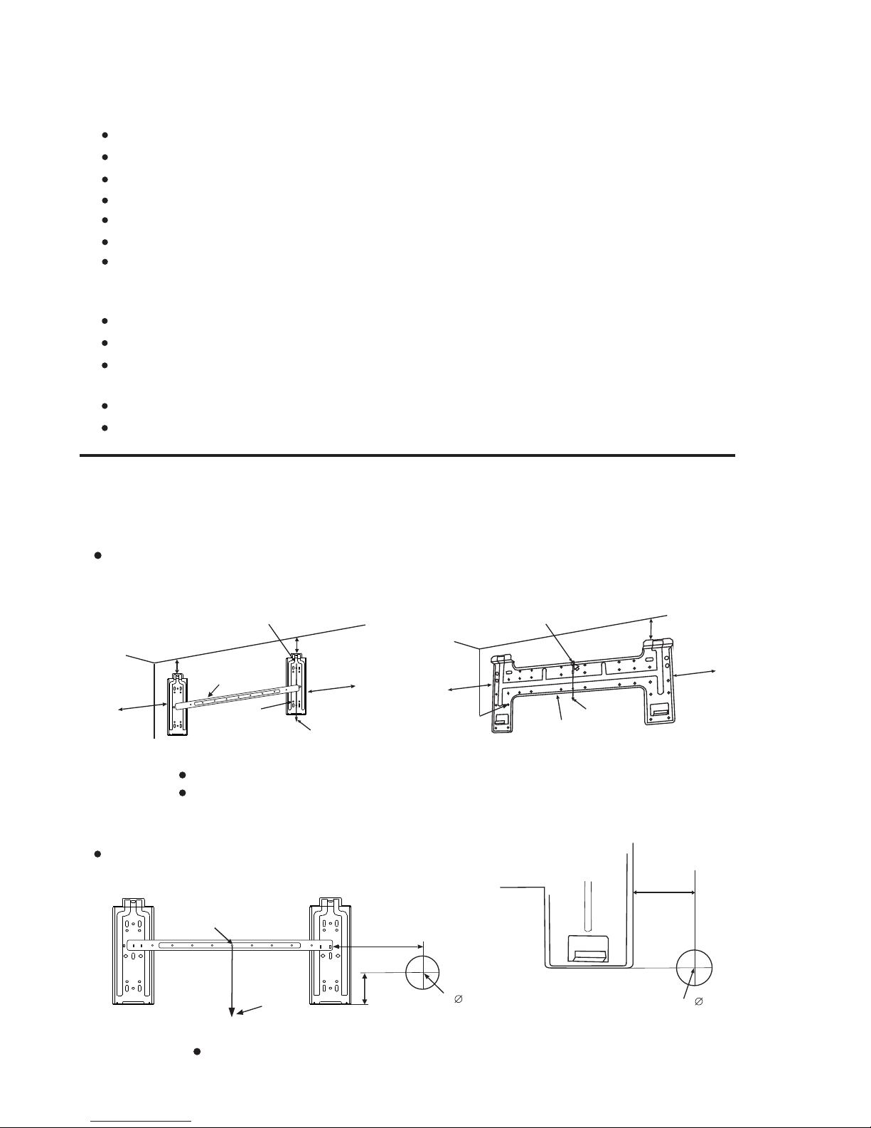
INSTALLATION OF THE INDOOR UNIT
Securing the mounting plate and drill on the wall
1
Secure the mounting plate
The mounting plate should be attached to the structural part of wall (post etc).
fasten string at the central hole
105mm or more
from sidewall
155mm or more
at least 250mm
from sidewall
Tapping screw
ST4×25(5)
mounting plate
NOTICE:
The holes at solid arrow position must be secured to avoid the shake of mounting plate.
When the expansion bolts are used, two holes ( 11×20 or 11×26 ) that the distance
between them is 450mm should be adopted.
Drill on the wall
Center of hole( 65mm)
Confirm the position of holes, and drill holes on the wall.
NOTICE:
Avoid places close to inflammable gas leakage.
Fasten string at the central hole
105mm or more
from sidewall
455mm or more
at least 250mm
from sidewall
Tapping screw
ST4×25(5)
mounting plate
plumb
40mm
plumb
fasten string at the central hole
105mm
45mm
Center of hole( 65mm)
plumb
A place for firm location of the unit, solid enough to bear the weight of the unit and not cause any shake.
at least 250mm
Page 7
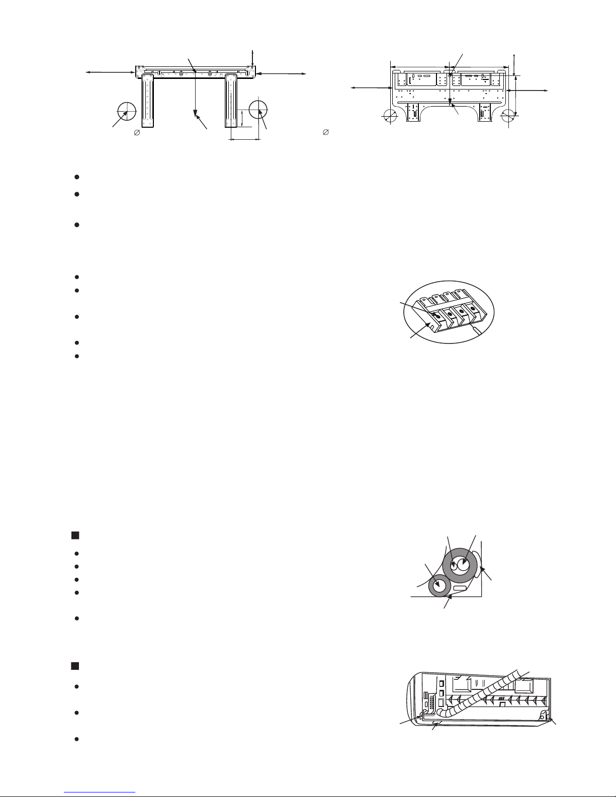
The drain hose must be arranged beneath the connecting pipe.
The drain hose must not be hunched or twisted.
While wrapping up the drain hose, do not pull it.
The drain hose through the room must be wrapped up by the
thermal insulation materials.
The connecting pipe and the drain hose must be wrapped up by felt
strip. Adiabatic pad should be used at where the pipe contacts
the wall.
NOTE:
1
2
3
ROUTE OF PIPE
If pipe comes out of the right side of the indoor unit, cut part
1 of the unit;
If pipe comes out of the lower-right side of the indoor unit, cut
part 2 of the unit;
If pipe comes out of the left side of the indoor unit, cut part 3
of the unit.
Installation of the drain hose
Wiring
2
Open the front grille;
Remove the screw from electrical box cover, pull the
electrical box cover away from the unit and set aside.
Remove the screw from fastener, pull the fastener
away from the unit and set aside.
Connect the cable.
Replace the fastener and electrical box cover.
Indoor unit terminal
Screw
Connecting cable
Diagram
3
4
Drain hose
gas pipe
Liquid pipe
felt
Adiabatic
underlay
NOTE:
NOTICE:
The holes at solid arrow position must be secured to avoid the shake of mounting plate.
When the expansion bolts are used, two holes ( 11×20 or 11×26 ) that the distance
between them is 450mm should be adopted.
Confirm the position of holes, and drill holes on the wall.
40mm
Pipe hole
plumb
fasten string at the central hole
at least 250mm
at least 180mm
at least 140mm
120mm
Center of hole( 65mm)
Center of hole( 65mm)
440mm
fasten string at the central hole
at least 80mm
230mm
440mm
at least 120mm
at least 120mm
¦
90mm
plumb
¦
90mm
Pipe hole
The appliance shall be installed in accordance with national wiring regulations.
The appliance must not be installed in the laundry.
The appliance must be installed 2.5m above the floor.
The appliance must be positioned so that the plug is accessible.
For some models whose cooling capacity are above 4600W (17000BTU/h),
an all-pole disconnection device which has at least 3mm separation distance in
all pole and a residual current device(RCD)with the rating of above 10mA shall
be incorporated in the fixed wiring according to the national rule.
Page 8
5
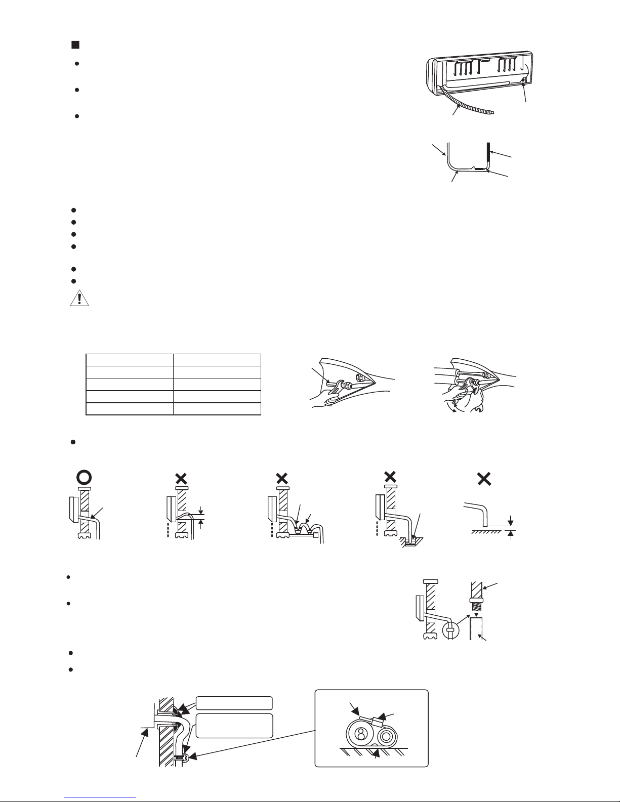
Arrangement of the drain hose
To drain the condensate water easily, the drain hose should be declined downwards.
The following 5 arrangement methods are incorrect.
Decline
downward
(Fig. 1)
(Fig. 2)
(Fig. 3)
(Fig. 4)
Water
leak
Standing water
air
Dip hose
into water
(Fig. 5)
50mm or less
above floor
6
Decline
downward
Water
leak
Water
leak
If you find the drain hose not long enough to connect with the indoor
unit, you can extend it with the hoses in the accessory box.
The drain hose through the room must be wrapped up with the special
adiabatic material.
Drain hose
Hose(ID 15cm)
PVC hard
Wall sealing and Pipe fastening
Use putty to seal the wall hole.
Use clamp (pipe fastener) to secure the pipe at specified position.
indoor unit
clamp
screw
get rid of unwanted part
seal with putty
secure the connecting
pipe with clamp
7
Installation of the indoor unit
Let pipe go through the wall hole and attach the indoor
unit to the mounting plate.(Press the rib of indoor unit
inside the hook of the mounting plate.)
the rib of indoor unit
the mounting plate
Bottom
Indoor unit
4
drain hose
If pipe comes out of the left side of the indoor unit, the drain hose
must be refitted, otherwise water leakage may occur.
Readjustment methods: Interchange the position of drain hose
and drain rubber plug.
Clearance is not allowed after refit, it would lead to water leakage.
Drain rubber
plug
READJUSTMENT OF DRAIN HOSE
5
Pipe Connection
Align the centre of joint in line with that of flare and tighten the nut of connecting pipe with wrench.(Fig. 2)
Put some seal oil to cover the joint and the flare.
The number of bent position of the pipe in the indoor unit should not exceed 10.
The number of bent position of the pipe in the indoor unit and the outdoor unit should not exceed 15.
The radius of bent position should be more than 10cm.
Please break the evaporator craft tube with pincers before connecting. After exhausting the inside air,
use the wrench to twist down the nut of connecting tube of the evaporator.(Fig. 1)
(Fig. 2)
(Fig. 1)
Evaporator
craft tube
Do not exhaust the inside air just by loosing the nut since there is the air of certain pressure
inside the tube of indoor unit.
Attention:
Please do not make extra effort for fear of damaging the expansion orifice.
DIAMETER OF PIPE
TORQUE(N·m)
12.0---15.0
33.0---36.0
40.0---45.0
73.0---78.0
φ6/φ6.35mm(1/4")
φ9/φ9.52mm(3/8")
φ12/φ12.7mm(1/2")
φ15/φ15.88mm(1/2")
Page 9
INSTALLATION OF THE OUTDOOR UNIT
1
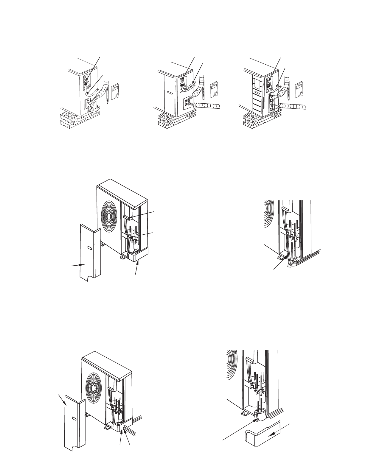
Wiring
1 Remove the self-tapping screws (2 pcs)
onthe maintenance board and take out the
maintenance board.
Maintenance
board
Terminal board
Fix the cable wire
with anchor cable
Piping cover
Please utilize outdoor pipe support when
the cable wire is led from the backside.
Outdoor pipe support
(Outdoor pipe support is not required
when leading the cable wire from other places).
The cable wire can be led from the back hole
of the piping hole or ejecting hole.
Maintenance
board
Piping cover
Ejecting hole
Right wiring
Back wiring
Sponge
Piping cover
2 Loosen the self-tapping screws (2 pcs) on
the fixing clip to loosen the fixing clip.
5 Install the maintenance board. After the pipes
and cable wire are installed, please seal the
sponge block as per drawing indication.
3 Loosen the fixing screw of the wire terminal
board, pass the power wire and signal wire
through the fixing clip. Then firmly fix the
power wire and signal wire on the terminal
board with the fixing screw. (Earth wire
must be connected firmly.)
4 Tighten the self-tapping screw on the fixing clip.
Wiring For Above 6000W Model (Above 21000BTU/h Model)
6
Single Split Model
Dual Split Model
Connecting
cable
Outdoor unit terminal
Connecting
cable
Outdoor unit terminal
Connecting
cable
Outdoor unit terminal
OR
Page 10
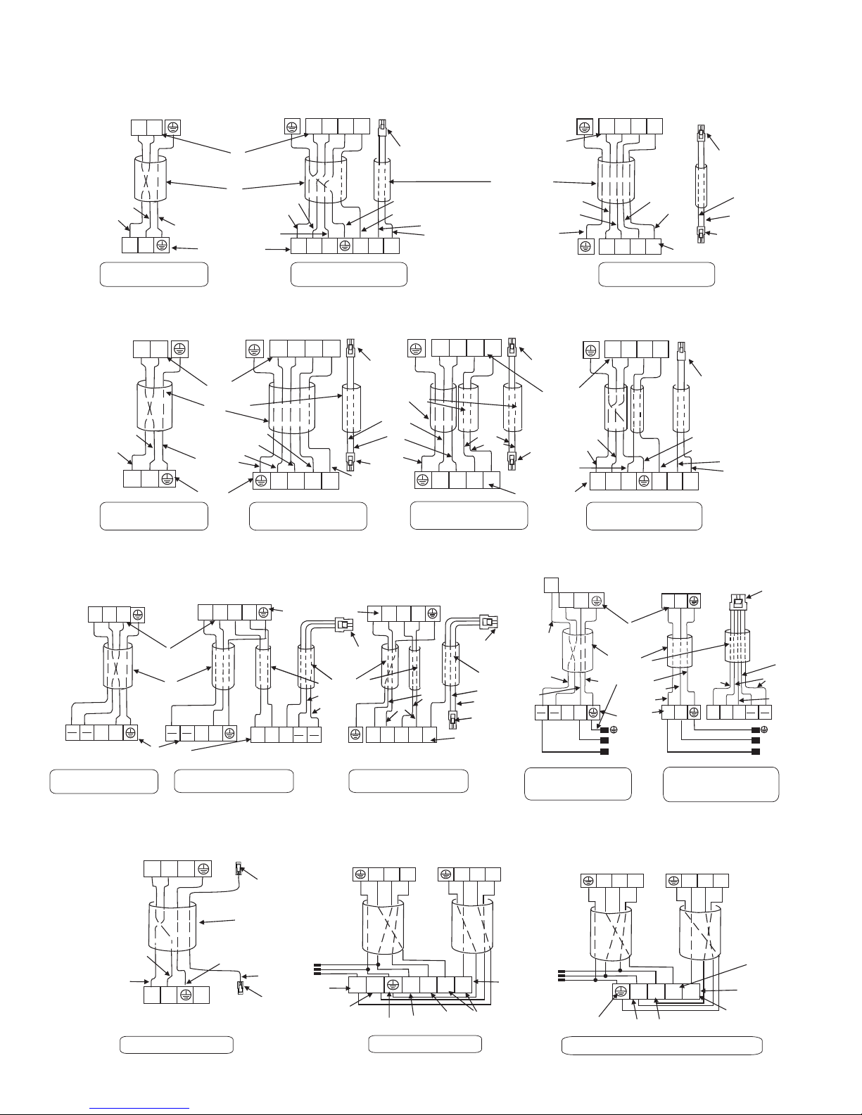
7
1500 -4600W Model (5000-12000BTU/h Model)
5000-5100W Model (17000-18000BTU/h Model)
Connect diagram
6000-10000W Model (21000-36000BTU/h Model)
2
L
N
N
L
Black
Indoor unit terminal
Blue
Connecting
cable
Brown
Yellow/Green
Blue
Brown
Black
Blue
Brown
Gray
N
L3
L22L1
L
N
L
3
2
4
5
R1
6
R2
Outdoor unit
terminal
安装说明
Yellow/Green
POWER
SOURCE
N
Blue
N
Blue
POWER
SOURCE
L
Brown
L
Brown
Cool only type
Heat pump type
(T3)(T3)
Indoor unit terminal
Outdoor unit
terminal
Black
Yellow/Green
2
N
2
N
Connecting
cable
Indoor unit terminal
Gray
Blue
Yellow/Green
3
2
N
3
2N
4
R1
R2
4
Brown
Blue
Brown
Brown
Cool only type
Heat pump type
Plug housing 1
Plug housing 1
Blue
Cool only type
OR
Connecting
cable
Outdoor unit terminal
Brown
Yellow/Green
Blue
3
2
N
3
2N
4
4
Brown
Black
Gray
Heat pump type
L
2
N
L
2A
2B
N
Connecting
cable
Indoor unit A terminal
L2N
Yellow/Green
Blue
Brown
Black
Black
Indoor unit B terminal
Outdoor
unit terminal
Connecting
cable
Indoor unit terminal
Outdoor unit terminal
Blue
Brown
Black
2
L
N
NL
2
Yellow/Green
Dual Split Model
Power
source
L
2
N
2A
2B
N
Connecting
cable
L2N
Yellow/Green
Blue
Brown
Black
Outdoor
unit terminal
Power
source
L
N
L
Blue
Brown
Inverter Type
Dual Split Inverter Type
Indoor unit A terminal
Indoor unit B terminal
Cool only and heat pump type
Heat pump type
Heat pump type
Plug housing 1
Blue
Plug housing 2
Plug housing 1
Plug housing 2
Blue
2
N
2
N
Yellow/Green
Indoor unit terminal
Brown
Connecting cable
Cool only type
Indoor unit terminal
Blue
Yellow/Green
3
2
N
3
2N
4
R1
R2
4
Brown
Blue
Brown
Plug housing 1
Blue
Brown
Heat pump type
Outdoor unit terminal
OR
Outdoor unit terminal
Blue
Black
Gray
Brown
Blue
3
2
N
3
2N
4
4
Brown
Heat pump type
Plug
housing 1
Plug
housing 2
Brown
Blue
3
2
N
3
2N
4
4
Heat pump type
Plug
housing 1
Plug
housing 2
Connecting cable
Yellow/Green
OR
Plug
housing 1
Plug
housing 1
Plug
housing 2
Connecting cable
Indoor unit terminal
2
N
L
NN2
L2
L1
L
Brown
Black
Blue
Blue
Yellow/Green
Brown
3
Brown
Black
Brown
Blue
Gray
Yellow/Green
N
L3
L3
2
L
3
2
4
L22L1
L
5
R1
6
R2
Outdoor unit terminal
2
NL
Blue
Yellow/Green
3
Brown
Black
Brown
N
L 2 3 4
Indoor unit terminal
Connecting cable
Gray
Connecting cable
Outdoor unit terminal
Heat pump type Heat pump type
OR
Page 11
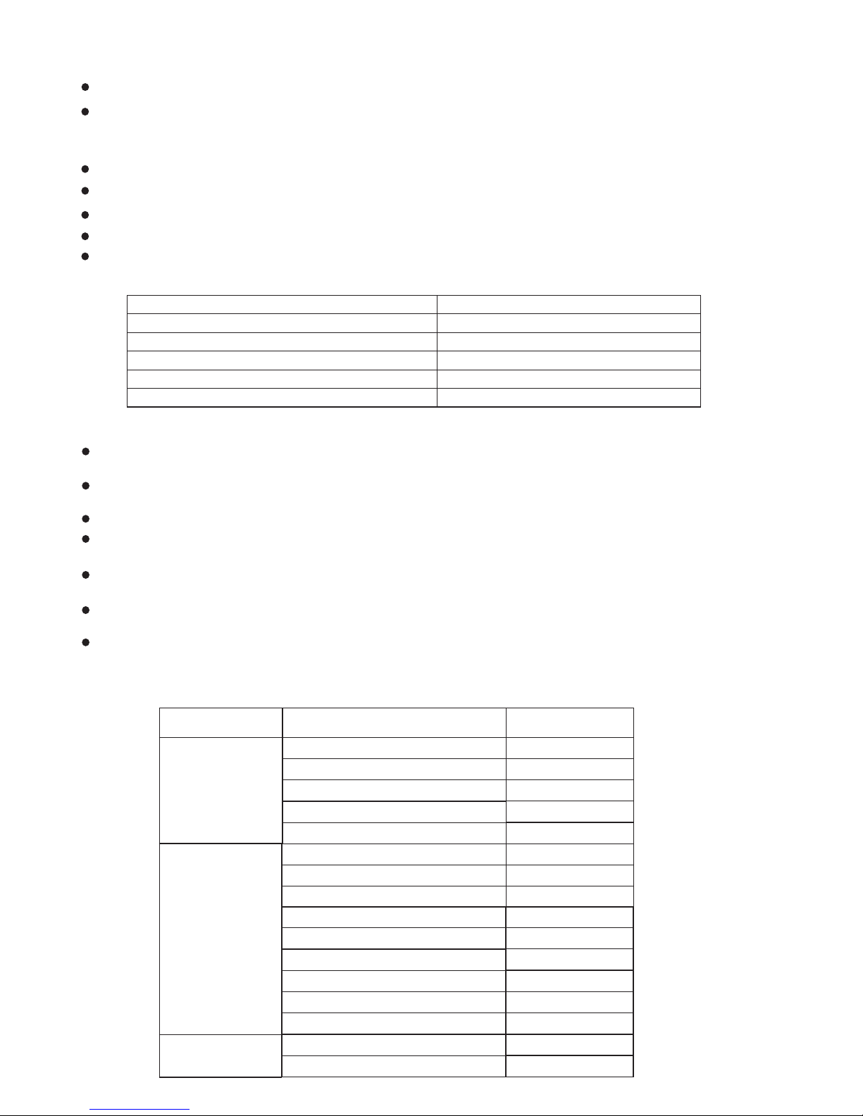
8
WARNING:
Special cable must be used to connect indoor unit and outdoor unit. It should be ensured
that the terminals are not influenced by external force. Poor connection may cause fire.
The electric box cover must be mounted and secured in position, otherwise fire or electrical
shock may occur because of dust or moisture.
The connecting cables must be clipped together.
Please take the electric circuit diagram attached to the indoor/outdoor units as major
reference while installing.
The power wire and signal wire between the indoor/outdoor units must be connected
one by one as per corresponding number on the wiring terminal board.
All the models shall be connected with the mains which has system impedance limitations.
While installing the unit, please see the following table for impedance information or consult
with the supply authority.(The following information and specifications are subject to change
without prior notice due to continuing research.)
The temperature of refrigerant circuit will be high, please keep the interconnection cable away
from the connecting tube.
SERIES MODEL
IMPEDANCE
≤0.204Ω
≤0.162Ω
≤0.148Ω
≤0.323Ω
6500W (22000BTU/h)
5100W (18000BTU/h)
2500W (9000BTU/h)
3500W (12000BTU/h)
R407C
series
6800W (24000BTU/h)
5100W (18000BTU/h)
3200W (11000BTU/h)
3500W (12000BTU/h)
R22
series
≤0.116Ω
≤0.160Ω
≤0.312Ω
≤0.312Ω
2500W (9000BTU/h)
≤0.467Ω
≤0.187Ω
≤0.124Ω
≤0.138Ω
≤0.268Ω
Dual Split Model(25+25)
Dual Split Model(25+35)
≤0.302Ω
2000W (7000BTU/h)
≤0.121Ω
3200W (11000BTU/h)
≤0.121Ω
3300W (11500BTU/h)
R410A
series
6800W (24000BTU/h)
5100W (18000BTU/h)
Notice:
If the interconnection cord for power supply has to be replaced, please see the
following table for reference.
If you find the color of connecting cable not comply with the top diagram, please take
real objects as major reference. But the terminal of the same sign must be joint with
the connecting cable of the same color.
If the signal wire has to be bought separately, choose electric wire above 0.75mm.
2
The plug housing 2 is connected to the matched receptacle housing of the outdoor unit.
The plug housing 1 is connected to the matched receptacle housing of the indoor unit.
If not include the connect diagram you need, please see the wiring diagram.
MODEL
SPECS (Interconnection cord)
2700W(10000BTU/h)
1.0mm
3200W(11000BTU/h)
-4000W(15000BTU/h)
4500W(16000BTU/h)
-8000W(28000BTU/h)
1.5mm
2
2
2.5mm
2
8500W(29000BTU/h)
-9500W(32000BTU/h)
4.0mm
2
6.0mm
2
10000W(34000BTU/h)
-11000W(38000BTU/h)
If not include the connect diagram you need, please see the wiring diagram.
Page 12
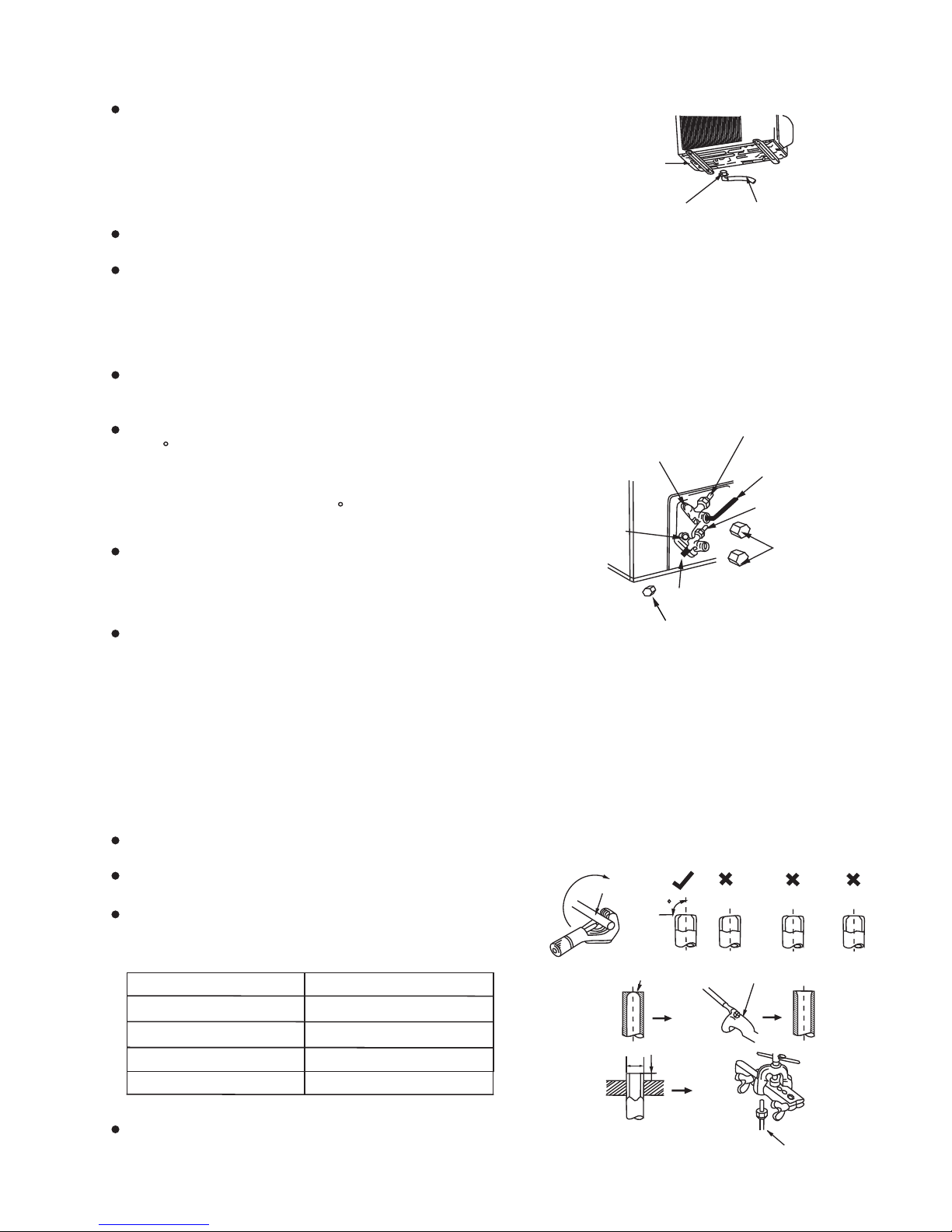
Process of flared tube
5
Use the pipe cutter to cut off the broken part of flare.
Remove burrs at the cut of the flare.
Insert a nut into the connecting pipe and do flaring
with specified flaring tools, reamers for example.
Check the quality of flaring technique.
Air exhausting
4
Installation of the drain joint (only for heat pump type)
Bottom
Double-channel
drain joint
Drain hose
Joint of the connecting pipe
Put some seal oil to cover the joint and the flare.
Align the centre of joint in line with that of flare and tighten the nut of connecting pipe
with wrench. ( Adjust the torque by the same method of connecting pipe for indoor unit.)
Insert the outdoor double-channel drain joint in one of the
bottom holes of the suitable size then connect drain hose
and joint together.
2
3
gas shut-off
valve
liquid shut-off valve
service port
gas connecting
pipe
liquid connecting pipe
valve nuts
service port cap
allen wrench
Screw down the cap of both gas shut-off valve and
liquid shut-off valve as well as the nut of service port.
Use Allen wrench to turn the valve cork of liquid side
at 90 counter-clockwise, and close it after 10 seconds.
Use soapy water to check the gas leakage especially
at all joint. If there is no gas leakage, please turn the
valve cork of liquid side at 90 counter-clockwise again.
Press the cork of service port at gas shut-off valve, 10
seconds later, when you see foggy gas discharged, that
means inner air is exhausted out.
Use Allen wrench to turn the valve cork of both liquid
shut-off valve and gas shut-off valve counter-clockwise
until they are completely open and then replace the
valve caps and tighten them.
9
Burr
Oblique
Connecting pipe
90
Roughness
Reamer
Burr
A
D
Connecting pipe
Do not vent refrigerant into atmosphere: refrigerant is a fluorinated greenhouse gas, covered by
Kyoto protocol, with a Global Warming Potential (GWP) =1900(R410A)/1600(R407C)/1700(R22).
Notice:
Outer diameter
A(mm)
2.0--2.5
3.0--3.5
3.5--4.0
4.0--4.5
φ6/φ6.35mm(1/4")
φ9/φ9.52mm(3/8")
φ12/φ12.7mm(1/2")
φ15/φ15.88mm(1/2")
Page 13
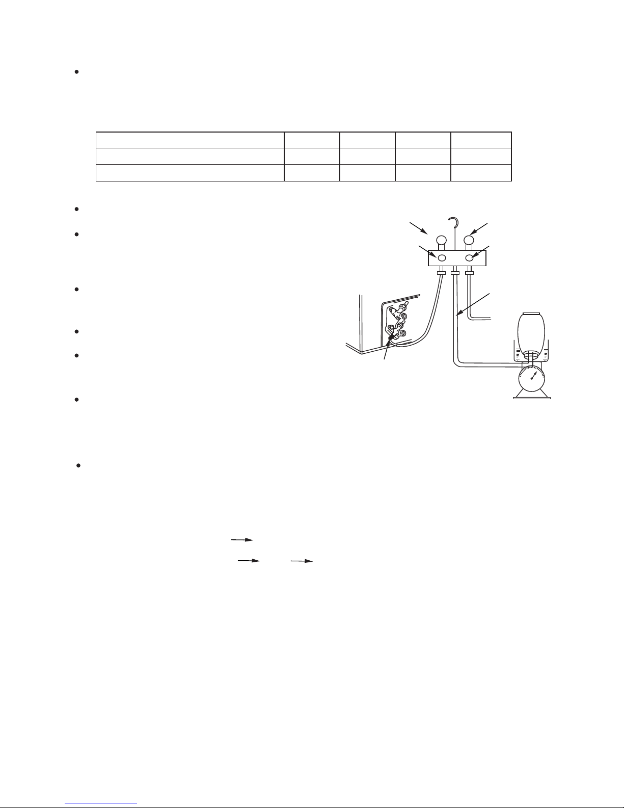
Operation test
Before test operation, wiring safety inspection must be carried out carefully again.
1. Emergency switch operation: Every press of emergency switch, the
air conditioner runs as in the following order:
Cool only type: Cool
Shut off
Heat pump type: Cool
Heat
Shut off
2. Remote controller operation: If the indoor unit sounds like Di, Di when pressing I/O button,
that indicates the air conditioner is under the operation of remote controller. After that, press
every button to test their functions.
7
Screw the gas shut-off valve to close, connect
charging hose(low pressure) to the service valve
and then open gas shut-off valve again.
Connect the refrigerant bottle to the charging hose
and then convert it.
Fill in liquid refrigerant as the above table.
Disconnect the manifold gauge after turning off the
shut-off valve, and then open gas shut-off valve again.
Exhaust the air as the above-mentioned method.
Tighten nuts and caps of each valve.
Service port
Manifold gauge
Low pressure
valve
High pressure
valve
Pressure meter
Charging line
Adding refrigerant
If the connecting pipe is longer than 7 metres, add refrigerant as needed. (Cool only type) added
amount A=(Lm-7m) 15g/m ; (Heat pump type)added amount A= (Lm-7m) 50g/m. ( A: amount
of added refrigerant, L: the length of connecting pipe)
6
10
7
0
0
8
15
50
9
30
100
10
45
150
The length of connecting pipe (m)
(Cool only type)added amount (g)
(Heat pump type)added amount (g)
3. operation: Open the front grille and press the check button. Switch on the powerCheck switch
source and then the operation test is activated. If the indicator lamps light up at first and then
go out in succession or the LED window of the indoor unit illuminates at first and then goes out,
the system is under normal operation. If one of the indicator lamps is flashing at all times, or
failure codes are displayed on the LED window of the indoor unit, the system has something
wrong and please check malfunction immediately.
Page 14

Page 15

Page 16
 Loading...