

Page 1
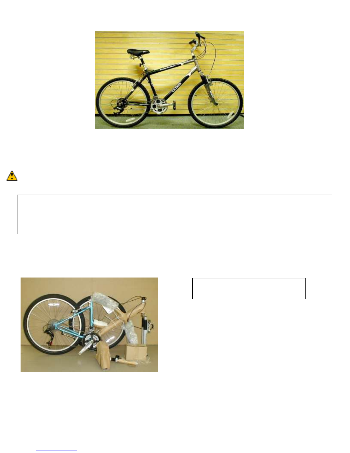
Final Assembly Instructions – Bikes with Threaded Headsets
FYI - Your bicycle may appear different
from those in photos.
Thank you for buying your new bicycle from L.L.Bean. Read these instructions carefully before beginning the final
assembly. Prior to shipping, our expert cycling technicians completely assembled and tuned your bicycle to ensure that
all components are functioning properly. However, for shipping purposes we have to partially disassemble your bicycle.
Although this bicycle has been factory pre-assembled, some loosening may have occurred during shipping and handling.
WARNING: BEFORE ATTEMPTING TO RIDE THIS BICYCLE, read the enclosed Owner’s Manual thoroughly. The
Owner’s Manual includes important information on customizing your bike for an optimal fit.
Tools required for final assembly:
Cutting-type pliers – for removal of packaging materials, including “zip-ties”
5mm & 6mm Allen wrenches – for tightening stem bolt
15mm wrench or adjustable wrench – for tightening pedals
Phillips head screwdriver – for tightening the front reflector
BEFORE GETTING STARTED:
PLEASE REMOVE BICYCLE FROM BOX AND REMOVE PACKAGING MATERIAL. Recommended tool –
diagonal cutting pliers, wire cutter, heavy duty shears, or multi-tool wire cutter.
QUESTIONS: Should you have any questions during the final assembly of your new bicycle, please call our product 3/1/13
specialists at 800-226-7552 any day between 8:00 a.m. and 10:00 p.m. Eastern. pg.1
Page 2
Quickrelease
in correct
closed
position
Head tube
Correct brake
position
Silver insert
Cable stop
Silver insert
connected to
cable stop
Disconnected
brake cable
Properly
connected
brake cable
Assembly Instructions
1. FRONT WHEEL AND FORK
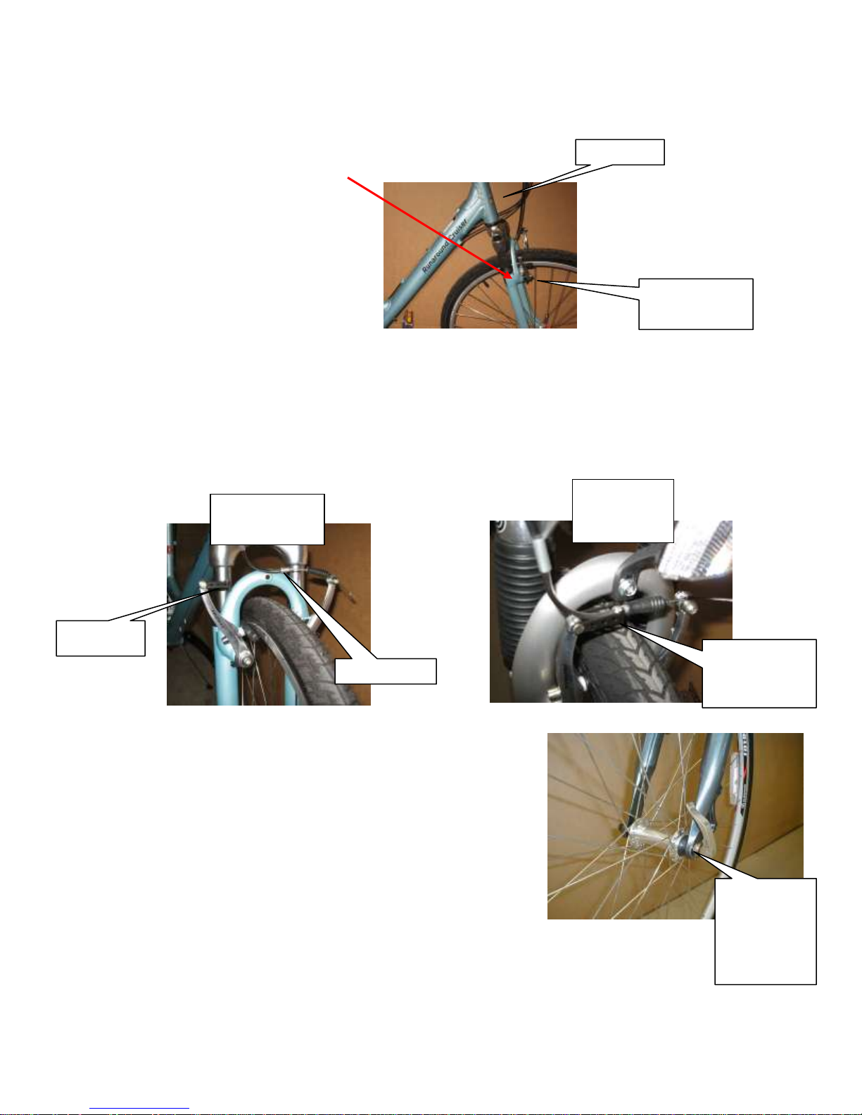
To fit your bike into the shipping box, the front fork may have been reversed
and the front wheel has been removed.
Brakes must be in front of the fork as seen here.
If you find the brakes behind the fork, spin the fork 180 degrees. Spin so the brake cable does not wrap around the head
tube. In proper position, the fork ends will face forward and brakes will be in front of the fork.
The brake cable may have been connected for shipping. It will need to be disconnected to install the wheel. To
disconnect, hold the brake arms together and remove the silver insert from the cable stop. To reconnect after wheel is
on, hold the brake arms together and insert the silver insert into the cable stop as show in the photo or as seen on the
rear brake of your bike.
To install the quick-release front wheel:
Remove the quick-release front skewer from the parts box. Check for the tread
direction on the tire sidewall (if the tread is directional there will be an arrow
on the sidewall).
With the tire in the correct direction, insert the wheel between the fork blades
so that the axle seats firmly at the top of the slots, which are at the tips of the
fork blades (the fork dropouts). Remove adjusting nut from skewer and slide
skewer through the fork and axle.
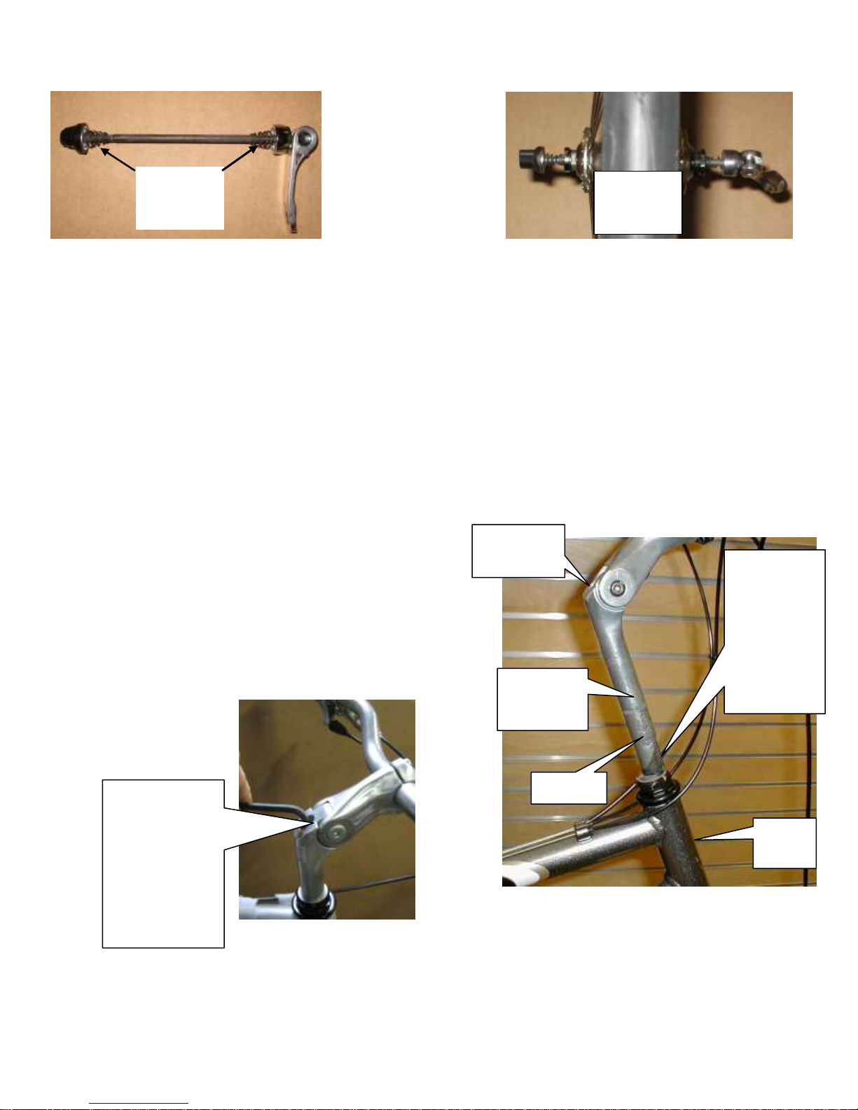
There should be a spring on each end of the skewer. Both should be facing with
the small end into the fork (refer to pictures below). While holding the wheel
firmly to the top of the slots in the fork dropout and at the same time centering
the wheel rim in the fork, tension and secure the quick release lever. After reconnecting
the brake cable, spin the wheel to make sure the it is centered in the frame and clears the brake pads.
QUESTIONS: Should you have any questions during the final assembly of your new bicycle, please call our product 3/1/13
specialists at 800-226-7552 any day between 8:00 a.m. and 10:00 p.m. Eastern. pg.2
Page 3
The stem
bolt works
by drawing
this wedged
piece up
until it locks
the stem in
place.
Minimum
insertion
line
Head
tube
Stem bolt
head
Tighten and
loosen the stem
bolt with a
6mm Allen
wrench. Turn
clockwise to
tighten, counter
clockwise to
loosen.
Stem
Correctly
installed
skewer
Note
direction
of springs
Correct quick-release tensioning:
1. Turn the lever to the open position so that the curved part faces away from the bicycle.
2. While holding the lever in one hand, tighten the adjusting nut until it stops.
3. Pivot the lever towards the closed position. When the lever is halfway closed, there must be firm resistance to turn it
beyond that point. If resistance is not firm, open the lever and tighten the adjusting nut in a clockwise direction.
4. Continue to pivot the lever all the way to the closed position so that the curved part faces the bicycle.
Note: If you can fully close the quick release without wrapping your fingers around the fork for leverage, and the lever
does not leave a clear imprint in the palm of your hand, the tension is insufficient. Open the lever, turn the adjustment
nut and try again. Continue until quick release lever closes properly. Reconnect the brake cable as explained above.
Please also refer to the Owner’s Manual for additional information.
2. INSTALL HANDLEBAR AND STEM.
Required tool – 6mm Allen wrench.
If there is a protective plastic cap on the end of the stem, remove and
discard it before inserting into the head tube. Insert handlebar stem
into head tube. You may need to loosen the stem bolt slightly.
Make sure to insert stem past the “minimum insertion line,” and then
adjust to desired height. Before tightening, align stem and handlebar
with the front wheel.
QUESTIONS: Should you have any questions during the final assembly of your new bicycle, please call our product 3/1/13
specialists at 800-226-7552 any day between 8:00 a.m. and 10:00 p.m. Eastern. pg.3
Page 4
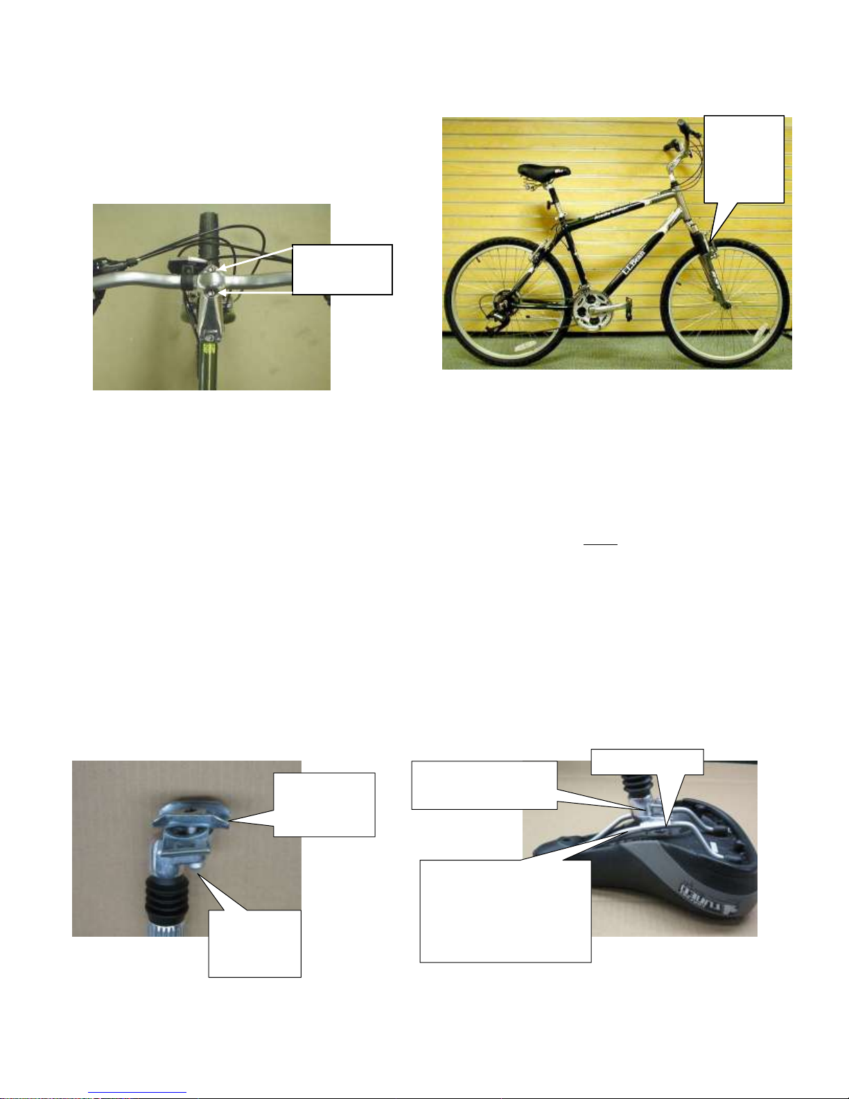
NOTE: After completing Step 2, Install Handlebar and
Stem, your bike should look like this – handlebar and
stem facing forward – with front brakes located in front
of fork.
Brakes
are to the
front of
the fork.
Handlebar
clamp bolts
Loosen
seat post
clamp bolt
Position saddle rails
between the seat post
clamping mechanism
and snug the seat post
clamp bolt
Saddle rails
Seat post clamping
mechanism
Top plate
turned for
mounting
Tighten stem bolt firmly. To check tightness, brace front wheel between your knees, then try to turn the handlebar left and right.
The stem should not move.
The handlebar should be aligned square to the tire, if not,
slightly loosen the stem bolt, adjust square and retighten.
Cables should be in brackets and routed in smooth rounded
paths (not pinched or bent).
The handlebars may have been rotated for shipping.
To adjust loosen the handlebar clamp bolts on the stem.
Rotate to desired angle and tighten the bolts. The bolts
should be tightened enough that there is no movement
when firmly pushing against the handlebar.
REMEMBER, the handlebar stem may be raised or lowered for comfort, but it should never be raised above the
“Minimum insertion line” marked on the stem.
3. ATTACHMENT OF SADDLE TO SEAT POST (If already attached skip this step)
Required tool- 6mm hex wrench
To fit your bike into the shipping box the saddle may not be attached to the seat post. Please follow the instructions
below to correctly attach your saddle.
To attach the saddle to the seat post, unpack the seat post and saddle. Loosen the seat post clamp bolt with a 6mm hex
wrench. Position the seat post clamp mechanism along the saddle rails. Make sure the clamping mechanism is clamping
on the straight part of the saddle rails and is not touching the curved part of the rails. Snug the seat post clamp bolt.
QUESTIONS: Should you have any questions during the final assembly of your new bicycle, please call our product 3/1/13
specialists at 800-226-7552 any day between 8:00 a.m. and 10:00 p.m. Eastern. pg.4
Page 5
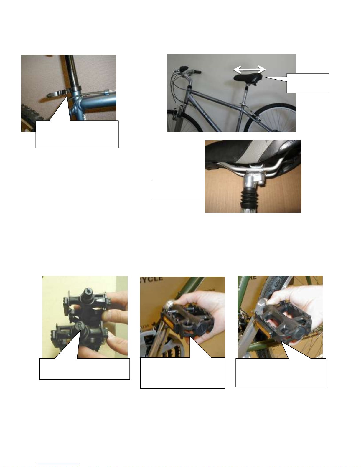
Pedals are marked “L” and
“R” on their spindles.
Place right pedal into right
crankarm and turn
clockwise.
Insert left pedal into left
crankarm and turn counterclockwise.
Open the quick-release
lever of the seat tube clamp
and slide in the seat post
Saddle set
horizontal
Seat mounted
correctly
Insert the seat post into the bike’s seat tube. The saddle is adjustable forward and back along the saddle rails and can be
angled up or down. The best starting position is with the saddle horizontal and in the middle of the seat rails. With the
bike on the ground find this position and tighten the seat post clamp bolt.
4. INSTALL PEDALS.
Required tool – 15mm open-end wrench, or adjustable wrench.
CAUTION: The right pedal has right-hand threads and must be installed in the right crankarm, tightening in
a clockwise direction. The left pedal has left-hand threads and must be installed in the left crankarm, tightening
in a counter-clockwise direction. To avoid cross-threading, carefully start and tighten pedals by hand. Then
tighten securely with a 15mm wrench.
QUESTIONS: Should you have any questions during the final assembly of your new bicycle, please call our product 3/1/13
specialists at 800-226-7552 any day between 8:00 a.m. and 10:00 p.m. Eastern. pg.5
Page 6
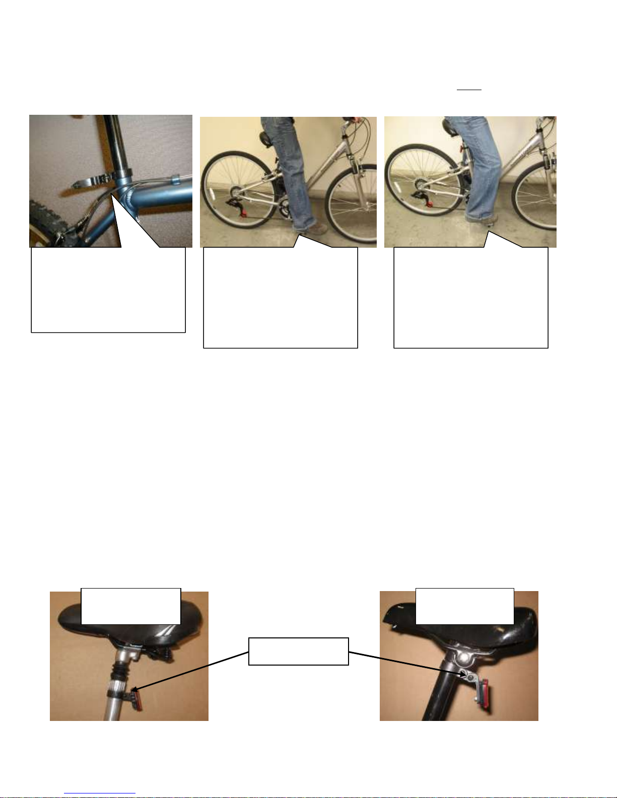
To raise or lower seatpost,
open the quick-release lever as
shown and close when
adjusted. If not equipped with
quick-release, loosen and
tighten hex head bolt.
To determine proper saddle
height, position right pedal at
the bottom of its revolution,
aligned with the seat tube.
While sitting on saddle, place
your heel on right pedal. Your
leg should be fully extended.
Adjust saddle height if
necessary and repeat. Now
place the ball of your foot
directly over the center of the
pedal (normal riding position).
This should result in the
correct bend at the knee.
Reflector with
adjustment screw
Reflector without
adjustment screw
Mounting screw
5. INSTALL SADDLE AND ADJUST SADDLE HEIGHT.
If the seat and seat post are not already installed, insert the seat post into the seat post tube.
WARNING: The seatpost may be raised or lowered for comfort, but it should never be raised above the
“minimum insertion line” marked on the seatpost.
Generally, you do not want to raise your saddle higher than determined by this method. If you have to rock your
hips to reach the bottom of the pedal stroke, then your saddle is too high. However, if while riding your bicycle,
this position doesn’t feel comfortable to you, adjust as necessary.
6. ATTACH REFLECTORS
Required tool – Phillips head screwdriver
The front and rear reflectors may have been adjusted or not installed to prevent shipping damage. Be sure to mount the
red reflector facing the rear of the bike and the white reflector facing forward. Both reflectors should be set
perpendicular to the ground and secured before riding.
Reflector styles may vary slightly. These instructions are a guide for the most common types.
To install a seatpost-mounted rear reflector (red), remove the reflector mounting screw and gently open the bracket
enough to slide over the stem. Position the reflector and secure with the screw. Use care not to over-tighten as the
bracket may crack. If the reflector has an adjustment screw, loosen the adjustment screw to set the reflector
perpendicular to the ground and tighten to secure.
QUESTIONS: Should you have any questions during the final assembly of your new bicycle, please call our product 3/1/13
specialists at 800-226-7552 any day between 8:00 a.m. and 10:00 p.m. Eastern. pg.6
Page 7
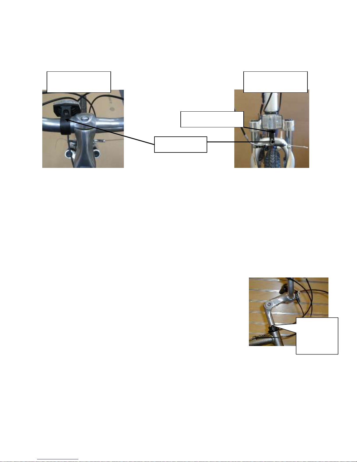
The stem
can be
moved up
and down.
Properly positioned
handlebar reflector
Properly positioned
fork reflector
Mounting screw
Adjustment screw
To install a handlebar-mounted front reflector (white), remove the reflector mounting screw and gently open the bracket
enough to slide over the handlebar on the left side of the stem. Position the reflector perpendicular to the ground and
secure with the screw. Use care not to over-tighten as the bracket may crack.
Fork mounted reflectors will be mounted but need to be adjusted to the proper position. Rotate the reflector upright.
Loosen the adjustment screw located below the reflector, set perpendicular to the ground and tighten to secure.
NOTE: For additional maintenance and safety tips, be sure to read your Owner’s Manual thoroughly.
Custom Fitting your Handlebar (adjustable stems only)
Your stem angle comes pre-adjusted for the average rider and may be perfectly satisfactory where it is. However, some
bikes have an adjustable “riser” stem. You may be able to raise or lower it, as well as move it farther away from you. If
you’d like to be sitting more upright, you can move it up and back towards you. If you feel that your riding position is too
upright, you can move it lower and out away from you.
Moving the stem straight up and down is the simplest way to make minor height
adjustments. This was covered in the assembly instructions. (Remember not to
raise the stem over the “minimum insertion line.”)
QUESTIONS: Should you have any questions during the final assembly of your new bicycle, please call our product 3/1/13
specialists at 800-226-7552 any day between 8:00 a.m. and 10:00 p.m. Eastern. pg.7
Page 8
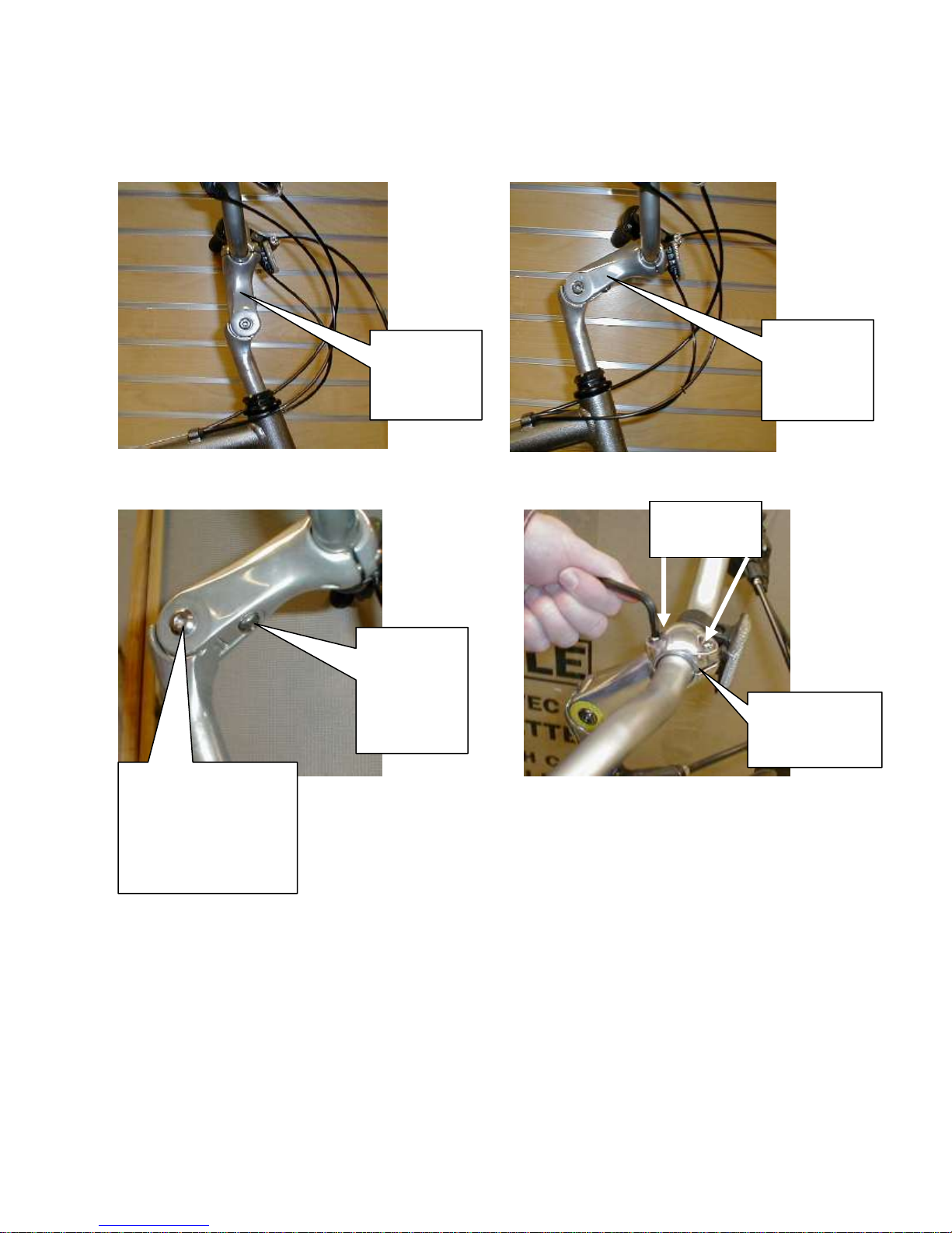
This space
should be equal
on both sides.
Riser
adjusted
fully upright
and back.
Riser
“clamp” bolt
needs to be
loosened to
disengage
Riser “through” bolt
may need to be
loosened first. It may
take an Allen wrench
on each side to keep it
from spinning.
After adjusting the riser angle you may need to rotate the handlebar back to a
more level upright position by loosening the two handlebar clamp bolts, rotating
the bar to the position you want, and retightening them. (Retighten them equally
by turning each one turn at a time, so the space between them and the clamp
base is equal on both sides.)
Riser
adjusted
fully down
and forward.
Handlebar
clamp bolts
Rotating the adjustable riser bar gives you more adjustment. To do this you may need to loosen the riser “through” bolt
(see below) a few turns using Allen wrenches (you might need two, one for each side). Loosen the riser “clamp” bolt at
the front of the riser (see below), holding the clamp away with your finger to disengage the teeth. Rotate the bar to the
desired position and retighten, tightening the riser “clamp” bolt first, and then the riser “through” bolt.
QUESTIONS: Should you have any questions during the final assembly of your new bicycle, please call our product 3/1/13
specialists at 800-226-7552 any day between 8:00 a.m. and 10:00 p.m. Eastern. pg.8
 Loading...