

Page 1
1 (4)
Functional description
Normal mode for the room thermostat when in
operation is displaying current room temperature.
The temperature setting of the room thermostat
can be changed using the “arrow up” or “arrow down” touch buttons. When the buttons are
touched, the temperature display shows more
brightly. The thermostat is then displaying the
set/desired room temperature. Once changes
have been made with the “arrow up” or “arrow
down” buttons, the thermostat returns to a reduced brightness level, once again displaying the
current room temperature.
The thermostat comes with a function LED which
shows whether the set temperature has been
reached or not. If the LED is off, the set temperature has been reached.
Installation
When tting, bear the following in mind:
• Fitting height, approx. 1.5 m above oor level.
• Best installed on an inner wall.
• Make sure there is circulation of air.
• Avoid secondary heat from other heat sources,
such as sunlight, lighting, etc.
Electrical connection
1. Remove the back cover of the thermostat.
2. Fit the back cover to the wall. If the back
cover is to be tted to an electrical box, the
pattress which comes supplied with the
thermostat should be used.
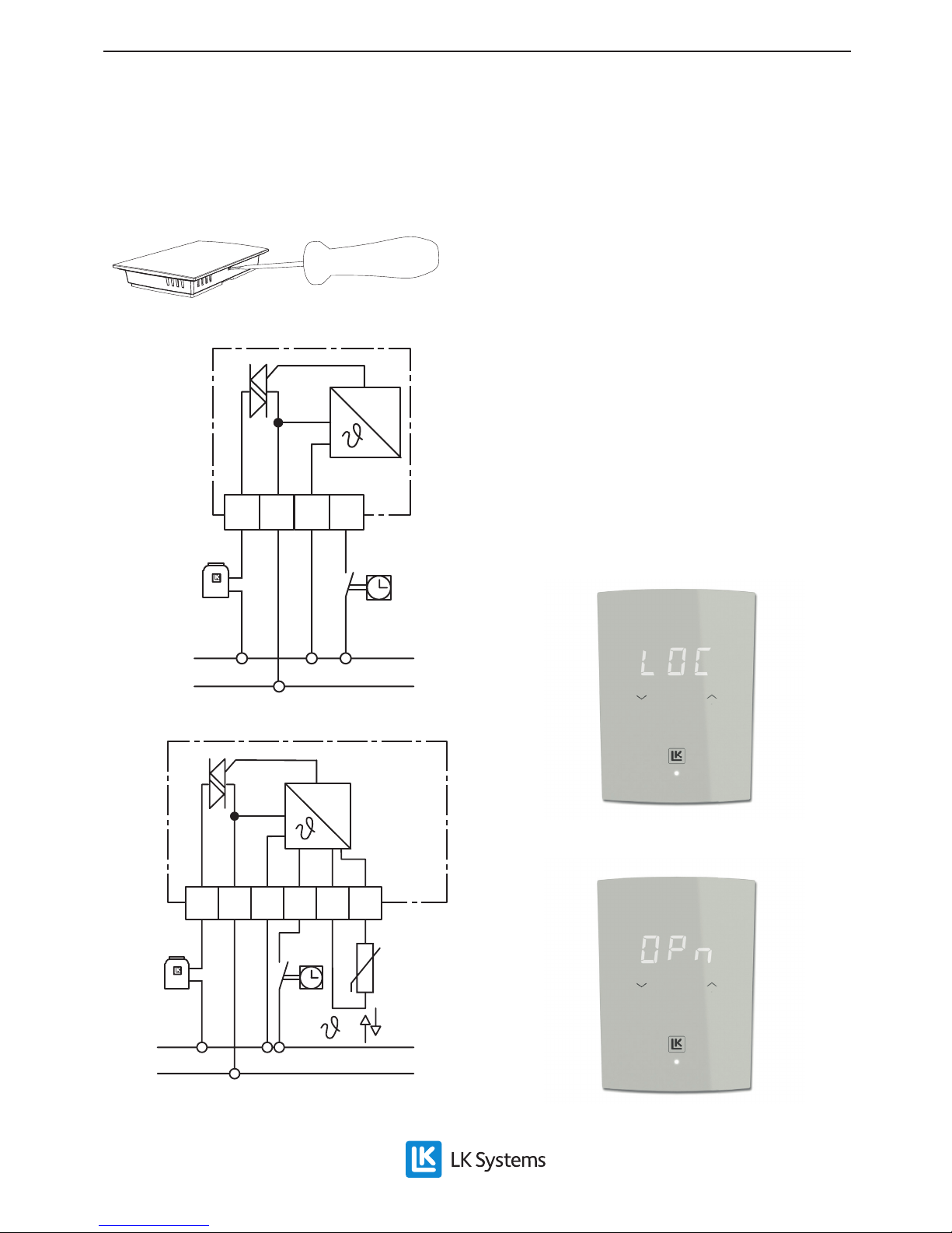
3. Electrical installation must be performed as
per the circuit diagram below.
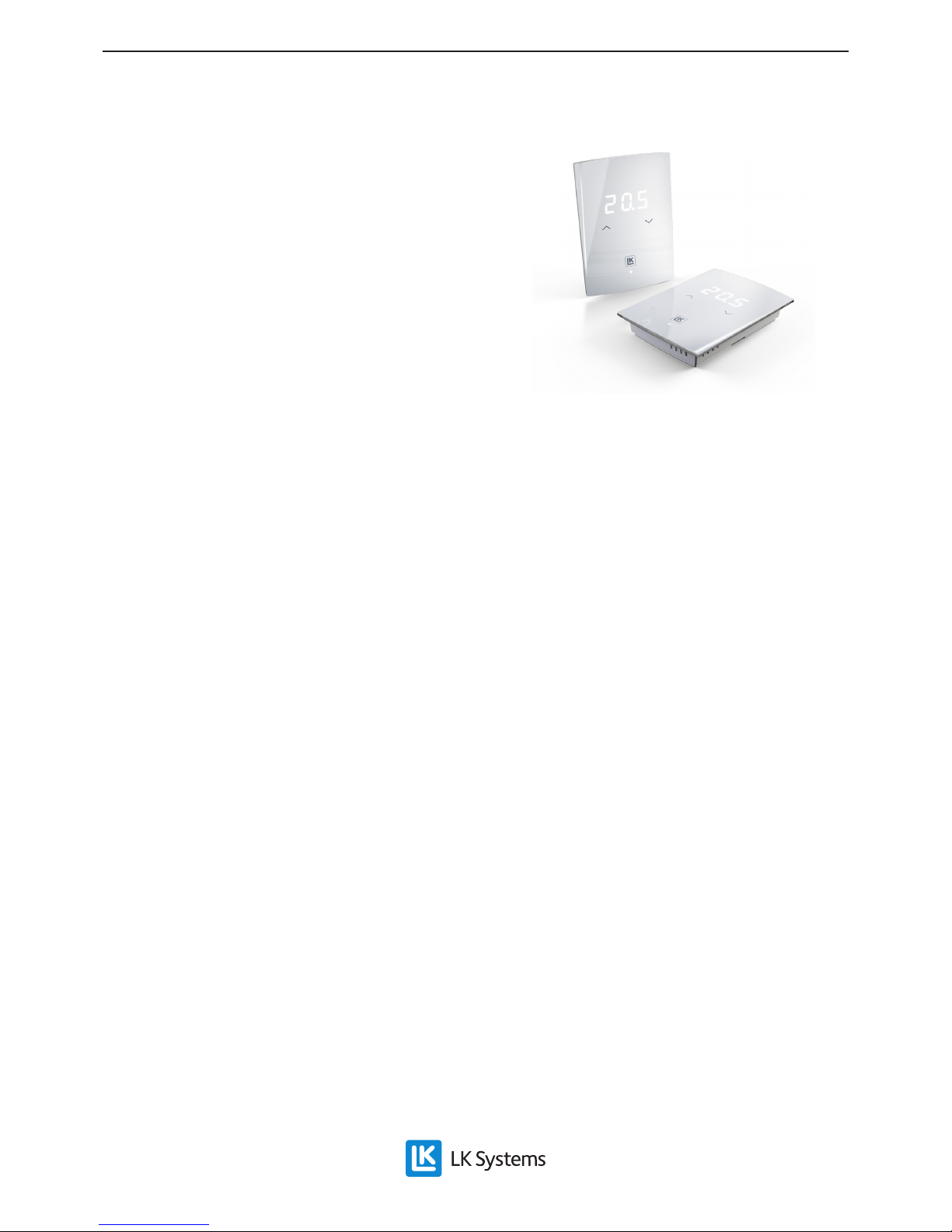
LK Room Thermostat S2 is an electronic room
thermostat with a triac output specially adapted
for the LK Floor Heating System. The room thermostat is used together with electrothermal actuators of normally closed (NC) type. To achieve
maximum energy efciency the thermostat uses
so-called self-modulating technology via signal
pulses to the valve actuator. The self-modulating
technology adjusts the output of the underoor
heating to the set temperature. Once the room
temperature approaches the set temperature, the
output of the heating is gradually reduced to prevent overheating.
LK Room Thermostat S2, 24V NC is available
in two different designs, S2 and S2 EXT, where
S2 EXT can be connected to LK Remote Sensor
ICS/S2 for controlling e.g. oor temperature. The
room thermostat is also used in so-called public
environments, where the temperature setting of
the thermostat can be locked by pressing buttons
in combination.
Product range
• LK Room Thermostat S2 NC
(Article no. 243 43 98): Basic thermostat for controlling room temperature
• LK Room Thermostat S2 EXT NC
(Article no. 243 44 00): Thermostat for controlling
room temperature or for controlling e.g. oor
temperature via LK Remote Sensor ICS/S2
(Article no. 241 73 23).
Accessories
• LK Remote Sensor ICS/S2, matches room thermostat S2 EXT (Article no. 241 73 23)
Spare parts
• LK Pattress S2, comes supplied with the thermostat, (Article no. 33454)
Particular benefits to note:
• Self-modulating technology via signal pulses for
maximum energy efciency.
• Modern design with polished vitreous surface
and touch temperature setting.
• Intended for mounting directly on a wall, or on
an electrical installation box.
• Option of connecting a remote temperature sensor for model S2 EXT.
• The room thermostat settings can be locked by
pressing buttons in combination.
• The temperature can be reduced via a separate
timer (timer not included).
• Silent thermostat function.
• Easy functional check via LED.
LK Room Thermostat S2, 24 V NC
EN.33.C.149.1511
Assembly instructions | LK Room Thermostat S2, 24 V NC
Page 2
2 (4)
EN.33.C.149.1511
Assembly instructions | LK Room Thermostat S2, 24 V NC
Temperature locking
For installation in e.g. a public environment,
locking of the thermostat’s temperature setting
may be needed.
• Locking is performed by pressing buttons in
combination. Hold both buttons, i.e. “arrow
up” and “arrow down” down for approximately 20 seconds. When the function is active,
the thermostat displays “LOC” for lock, i.e.
the thermostat is locked. The room thermostat will then return to displaying the current
room temperature. If someone tries to change
the temperature, the thermostat will display
“LOC” to show that the thermostat is locked.
• Unlocking is performed in the same way as
locking, i.e. hold both buttons (i.e. “arrow
up” and “arrow down”) down together for
approximately 20 seconds. The room thermostat shows that the function has been deactivated by displaying “OPn” for open.
Text message for locked temperature setting
Unlocked temperature setting, displayed on unlocking
Note: If LK Connection box NC or LK Connection Box 1 is used, follow the circuit
diagram of the product in question instead.
Removal of the thermostat back cover
24V~
1
2
45
Connecting LK Room Thermostat S2
24V~
1
2
45
11
12
Connecting LK Room Thermostat S2 EXT with option of
connecting a remote sensor
Page 3
3 (4)
EN.33.C.149.1511
Assembly instructions | LK Room Thermostat S2, 24 V NC
Connection of LK Remote Sensor ICS/S2
LK Remote Sensor ICS/S2 is designed to be used
together with LK Room Thermostat S2 EXT when
e.g. oor temperature is to be controlled. The
sensor is connected to terminal 11 and 12 of the
thermostat, see circuit diagram. If necessary, the
remote sensor can be connected by extension cable up to 50 metres. For extension purposes, use
the same cable area as the sensor, or a larger one.
Note: Avoid routing in parallel with a high voltage installation, e.g. on cable tray.
Position the remote sensor as follows:
Concrete & screed encapsulated systems
Before applying the concrete or screed, a conduit
is normally positioned approximately 1.5 metres into the room. Note that positioning should
be at a point which is representative of the surface/zone which is to be controlled. The end of
the sensor must terminate centrally between two
oor heating pipes. Seal the end of the conduit
with tape or similar so that concrete cannot enter
it. Try to position the conduit as high as possible
in the structure, as this will result in better performance when controlling the oor surface temperature. Insert the remote sensor in the conduit
before applying concrete or screed and connect to
the thermostat as described above.
LK HeatFloor 22, LK EPS 30/50/70 or LK Silencio
Cut a slot in the top of the slotted board. Position
a conduit in the cut slot, terminate the conduit
centrally between two heat distribution plates.
Note that positioning should be at a point which
is representative of the surface/zone which is
to be controlled. Insert the remote sensor in the
conduit before laying the oor and connect to the
thermostat as described above.
Underfloor heating in secondary spaced boarding
Position a conduit between two heat distribution
plates and secure the conduit in the edge of the secondary spaced boarding using conduit clamps.
Note that positioning should be at a point which
is representative of the surface/zone which is
to be controlled. Insert the remote sensor in the
conduit before laying the oor and connect to the
thermostat as described above.
Switching off the temperature display and LED
The temperature display and function LED on
the room thermostat can be switched off. The
thermostat is still active after the temperature
display and LED have been switched off. To read
off or change the temperature, the temperature
display comes on once one of the touch buttons
is touched. The thermostat then returns to unlit
mode. Switching off the temperature display is
ideal for bedrooms.
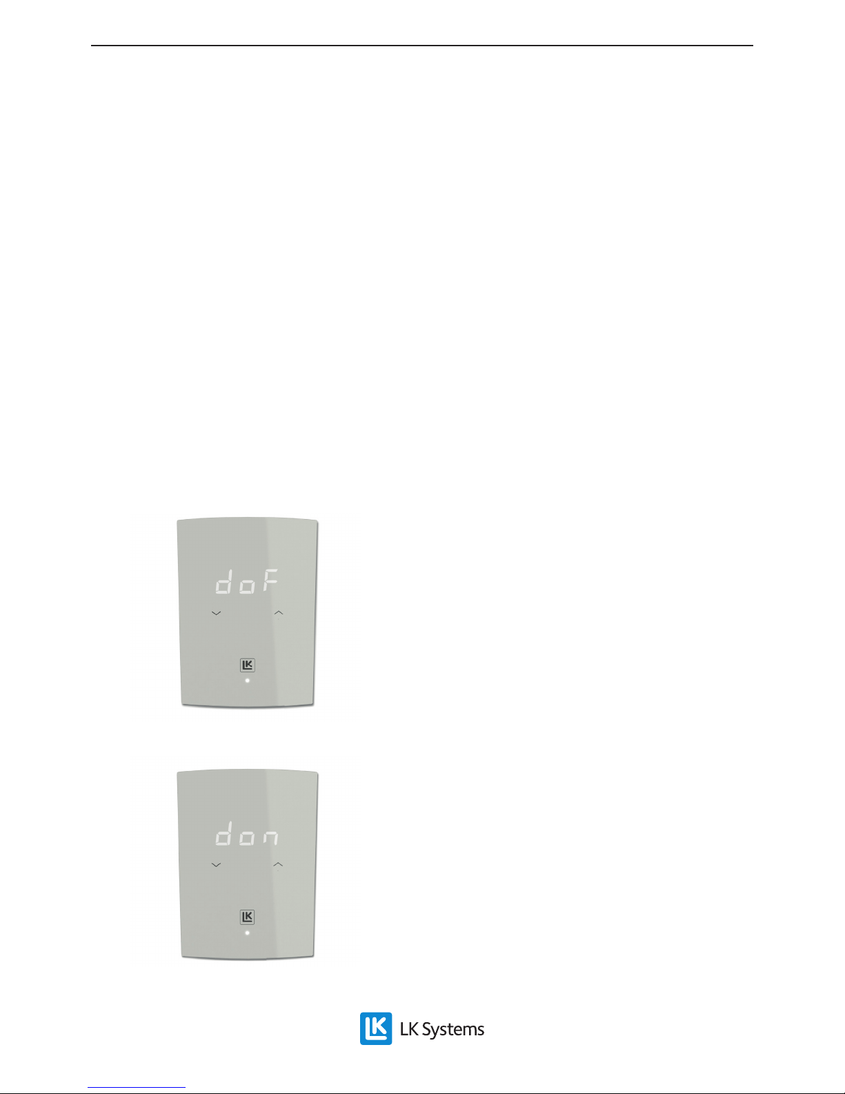
• The temperature display of the room thermostat is switched off by holding down the
right arrow button for approximately ve
seconds. When the function is active, the
thermostat shows “doF” for display off.
• To return to normal temperature display
(on), hold the right arrow button down for
approximately ve seconds. When the function is deactivated, the thermostat will show
“don” for display on.
Text message for switch-off of temperature display
Text message for return to temperature display “on”
Page 4
4 (4)
EN.33.C.149.1511
Assembly instructions | LK Room Thermostat S2, 24 V NC
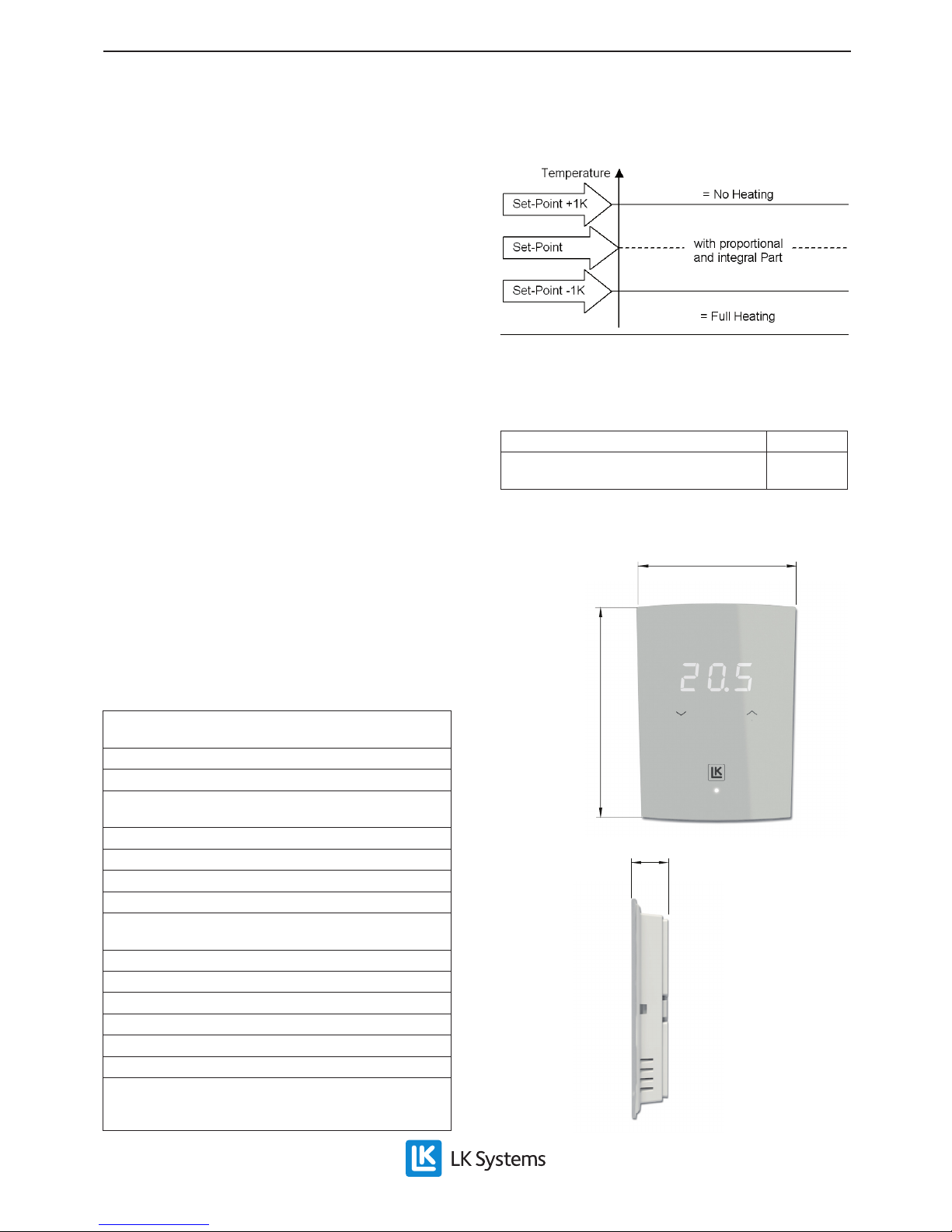
Temperature range for self-modulation
Self modulation 0%
Self modulation changing
Self modulation 100%
Temperature range for self-modulation, cycle time 42 min.
Energy declaration in accordance with
EU 811/2013
Temperature regulator class IV
Temperature regulator’s contribution to
seasonal space heating energy efciency
2%
Dimensions
80
112
16
LK EPS 16
Position a conduit along the long side of the oor
heating installation so that it is pointing towards
the nearest short side. At the short side cut a jack
approximately 2 metres long in the EPS board
measured from the short side. The conduit is positioned in this jack. Insert the remote sensor in
the conduit before laying the oor and connect
to the thermostat as described above. Note that
positioning should be at a point which is representative of the surface/zone which is to be controlled.
LK Clip Rail 8/ LK Clip Rail 12
Position a conduit along the long side of the oor
heating installation so that it is pointing towards
the nearest short side. At the short side, route the
conduit in the centre between two oor heating
pipes and connect as normal approximately 1.5
metres in. Seal the end of the conduit with tape
or similar so that concrete/ooring compound
cannot enter it. Insert the remote sensor in the
conduit before applying concrete or screed and
connect to the thermostat as described above.
Note that positioning should be at a point which
is representative of the surface/zone which is to
be controlled.
Technical Data LK Room Thermostat S2
Voltage 24 V AC (20….30 V, 50….60 Hz) NC normally
closed
Switching capacity max 22 W (625 mA)
Intrinsic power 2 W
Maximum of ve LK Actuator 24 V NC items per room
thermostat
Temp. range 5–45 °C
Input for temperature reduction -3K
Cycle time for self-modulation 42 min
Range for self-modulation 2K
Colour: housing and pattress – white RAL 9003; cover
glass – polished white/ice grey
Protective class III
Protection class IP30
Storage temperature -25 to + 80 °C
Rel. humidity (warehouse) <80 % non-condensing
Operating temperature 0 to +50 °C
Remote sensor, length 3 m, type NTC 10 kΩ (option)
Dimensions 80x112 x 16 mm
Overall dimensions with pattress tted 80 x 112 mm
Overall dimensions without pattress tted 65 x 98 mm
LK Systems AB, Box 66, 161 26 Bromma, Sweden | www.lksystems.se
 Loading...