

Page 1

+
LiveU Xtender
User Guide
and 2.0
DOC00034
Version 6.3
Part Number:
Page 2

LiveU Xtender User Guide
About This Guide
This user guide describes how to use the LiveU Xten der to increase network
reception of the LiveU Live Video Uplink units to which it is connected. T h e
LiveU Xtender can be used with the LU70 or LU40 units.
• Chapter 1, Introdu ci n g the Liv eU Xte nder, page 7, introduces the
LiveU Xtender, describes the conte nts of its suitcase and describes the
LiveU Xtender components.
• Chapter 2, LiveU Xtender Getting Started, page 13, describes how to
set up and get started using the LiveU Xtender.
• Appendix A, Limitation of Liability and Warranty, page 29, provides
the limitations on liability and warranty.
• Appendix B, FCC Compliance Statement, page 31, provides the FCC
compliance information.
Intended Audience
This user guide is intended to be used by operators of the LiveU Live Video
Uplink LU40 and LU70. The user guide assu m e s that operators are familiar
with any video equipment or infrastructure to which these LU units are
connected.
Additional Documentation
• LiveU LU70 and LU40 User Guide: Each user guide describes an LU live video uplink
unit. These user guides instruct camera operators about how to use the LU unit to
broadcast live stre am ing video.
• LiveU LU-1000 Studio Server User Guide: Describes how to use the LU-1000 live
video server software, which enable s yo u to receive, v i ew and conf igure high-quality live
video transmitted from LU70 units in the fie ld .
• LiveU LU2000 Server (MMH) User Manual: Describes how to use the LiveU LU2000,
which provides multiple Multi-Media Hub s (MMHs) that e nable yo u to rec e ive , view and
configure high-quality live video trans m itte d fro m LU units in the fie ld.
• LiveU Center User Guid e: Describes how to remotely manage and control LU units and
MMHs on an LU2000 server through a standard Interne t brows er.
2
Page 3

Table of Contents
Table of Contents
About This Guide ......................................................................................................... 1
Intended Audience ................................................................................................. 2
Additional Documentation .................................................................................... 2
Table of Figures ........................................................................................................... 4
Support and Contacting Information ....................................................................... 5
Chapter 1: Introducing the LiveU Xtender ............................................................... 7
Introduction ...................................................................................................................... 7
LiveU Xtender System Architecture ...................................................................... 8
What’s in the Su itcase? .................................................................................................. 9
LiveU Xtender Components ........................................................................................ 10
Sta t u s LED s ...................................................................................................................... 12
Chapter 2: LiveU Xtender Getting Started ............................................................. 13
Workflow Overview ....................................................................................................... 13
Step 1, Installing the Hardware ................................................................................... 14
Vehicle Rooftop Installation ................................................................................. 14
Tripod Installation ................................................................................................... 17
Step 2, Connectin g the LiveU Xtend er to the LU Device ...................................... 18
LAN Connection ..................................................................................................... 18
USB Connection...................................................................................................... 19
Wi-Fi Connection .................................................................................................... 20
Step 3, Connecting the Power Source...................................................................... 23
Step 4, Turning On the LiveU Xtender ........................................................................ 24
Turning Off the LiveU Xtender .............................................................................. 24
Step 5, Configuring the LiveU Xtender Connection Type ...................................... 25
Step 6, Verifying the Connec tion ............................................................................... 26
Appendix A: Limitation of Liability and Warranty ................................................. 29
Limitation of Liability and Warranty ........................................................................... 29
Appendix B: FCC Compliance Statement ............................................................. 31
3
Page 4

LiveU Xtender User Guide
Table of Figures
Figure 1: LiveU X tender .......................................................................................................... 7
Figure 2: LiveU LU and Xtender Architecture .................................................................... 8
Figure 3: LiveU Tr ipod Xtender ............................................................................................ 10
Figure 4: LiveU Rooftop Xtender ........................................................................................ 10
Figure 5: SIM Ca rd Slots ....................................................................................................... 11
Figure 6: Status LEDs ............................................................................................................. 12
Figure 7: Workflow – Setting Up the LiveU Xtender ......................................................... 13
Figure 8: Positioning LiveU Xtender on a Vehicle Rooftop............................................ 14
Figure 9: Positioning LiveU Xtender on a Vehicle Rooftop – Cable Connections .... 15
Figure 10: LiveU Xtender Space Requirements – Bottom Side ..................................... 15
Figure 11: Three Shark Fin Antennas .................................................................................. 15
Figure 12: Distance Between Antennas ........................................................................... 16
Figure 13: Mounting the Three Directional Antennas .................................................... 17
Figure 14: LiveU Xtender LAN (Ethernet) Port .................................................................. 18
Figure 15: LU40 and LU70 LAN (Ethernet) Ports ............................................................... 18
Figure 16: LiveU Xtender USB Port ...................................................................................... 19
Figure 17: LU70 USB Ports ..................................................................................................... 19
Figure 18: LiveU Xtender to Wi-Fi Access Point Connection ......................................... 20
Figure 19: LU70/LU40 Connectivity .................................................................................... 21
Figure 20: Wi-Fi Client Belt ................................................................................................... 22
Figure 21: Wi-Fi Client-to-LU70 USB Power Cable ............................................................ 24
Figure 22: Xtend er Interface Settin g s Window ................................................................ 25
Figure 23: xTender WiFi Link ................................................................................................. 26
Figure 24: Remote Antenna Wi-Fi ‒ Xtender .................................................................... 26
4
Page 5

Support and Contacting Information
Support and Contacting
Information
► US and International:
LiveU Inc.
2 University Plaza Drive
Suite 505
Hackensack, New Jersey, 07601
USA
Tel: 1-(201)-742-5228
Fax: 1-(201)-623-4838
USA and the Americas: [email protected]
International: [email protected]
► Technical Support:
For 24/7 support, cal l:
US and Latin America:
Tel: 1-(877)-88-LiveU (54838)
Email: [email protected]
International:
Tel: 1-(609)-997-0600
Email: [email protected]
5
Page 6

LiveU Xtender User Guide
Blank page for double-sided printing
6
Page 7
1
Introducing the LiveU
Tripod
Xtender
This chapter introduces th e LiveU Xtender, describes the contents of its
suitcase and describes the LiveU Xtender components.
Introduction
External antenna for extra-strong resiliency in extreme scenarios
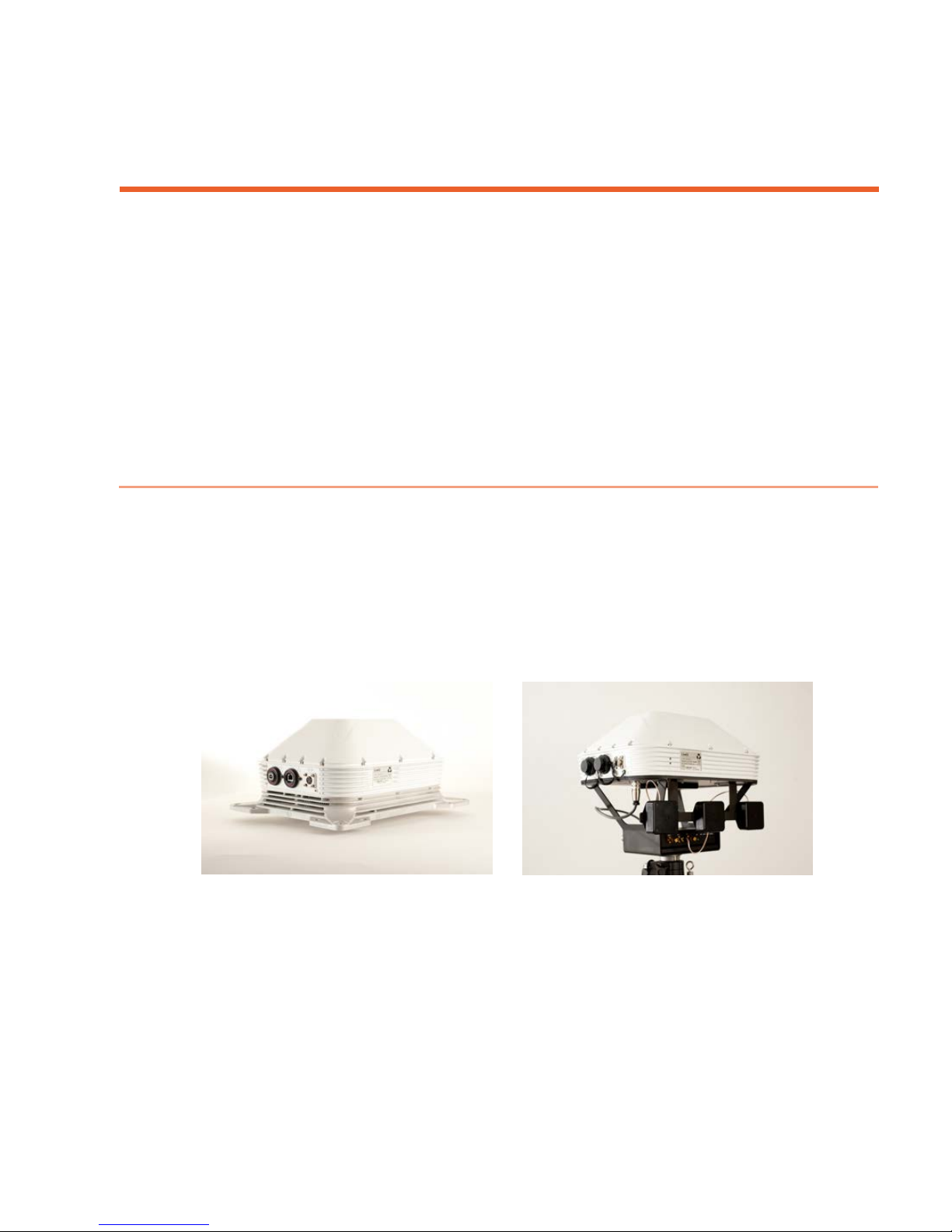
The LiveU Xtender is a lightweigh t external antenna unit that increases
network reception and provides additional resiliency for live video transmission
in extreme scenarios, such as heavily crowded locations.
The LiveU Xtender can be mounted on a tripod or on a vehicle rooftop.
Figure 1: LiveU Xtender
The LiveU Xtender add s seven addition a l network connections (six cellula r
modems and one Wi-F i) to LiveU’s LU profession al-grade backpack and covers
all current 3G/4G LTE cellular network bands worldwide. The combined LU and
Xtender solution support s up to 15 network connections. The LiveU Xtender
can service all the LU units in its vicinity, one at a time.
Rooftop
7
Page 8
LiveU Xtender User Guide
The LiveU Xtender enables a revolutionary mobile newsgathering (MNG)
vehicle with satellite-like reliability, faster setup time and lower overheads
than traditional SNG trucks.
The LiveU Xtender can connect to the LU40 and LU70 units using any of the
following options:
• LAN (for a direct connection between the LiveU Xtender and the LU
device).
• USB (for direct connection to the LU70).
• Wi-Fi (for a remote connection). A Wi-Fi Access Point and Wi-Fi Client are
required and may be provided.
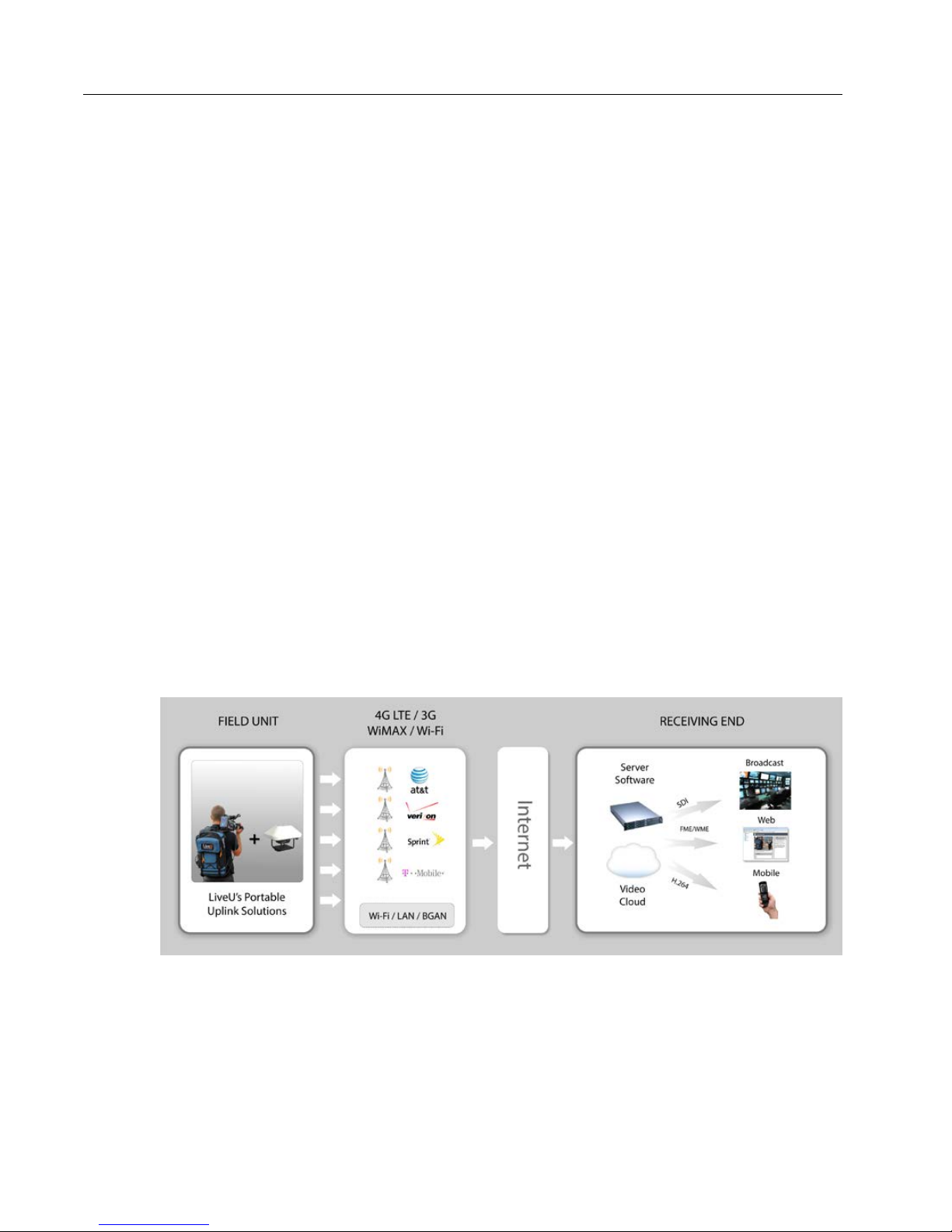
LiveU Xtender System Architecture
A video camera is connected to an LU live video uplink unit.
The LU unit is connected to the LiveU Xtender via LAN cable, USB cable or
via Wi-Fi (Wi-Fi Access Point and Wi-Fi Client).
The LU unit modems and the LiveU Xtender modems work together to
stream li ve audio and video from the field location to t he LU-1000 or the
LU2000 central server, which is usually located in a broadcasti ng cen ter.
Figure 2: LiveU LU and Xtender Architecture
8
Page 9
W hat’ s in the Suitcase?
CBL00132
RJ45 External Harness, 100 cm
CBL00190
Remote Antenna Kit Antenna Connection Cable, 24 cm
The following describes the components provi ded in the Live Xtender suitcase:
• LU Xtender unit.
• A dedicated 12-volt powe r supply that connects to any standard
110VAC / 220VAC power source.
• A Wi-Fi Access Point and Wi-F i Client, including the antennas of each.
• Rain cover.
Introducing the LiveU Xtender
NOTE
NOTE
NOTE
The LiveU Xtender uses a standard Anton Bauer or a video-mount
battery. No batteries are provided.
Do not use other USB cables ins tead of the provided cable s.
The LiveU Xtender has a standard tripod adapter. No tripod is
provided.
The following table lists the part nu m bers for the various cables and antennas
that can be used for Wi-Fi c onnectivity.
Table 1: Wi-Fi Connectivity Components
Part # Description
ANT00010 Antenna
ANT00011 Antenna
CBL00131 AC/DC External Harness, 120 cm
CBL00133 USB External Harness
CBL00158 Power Supply (from a triple USB)
CBL00159 Sealed Circular Ethernet Cable
CBL00160 Remote Antenna Kit LiveU Xtender-to-Powe r C able
CBL00161 External-Charger-to-Remote-Antenna-Kit Power Cable, 60 cm
CBL00162 LU40/LU70-to-Remote-Antenna-Kit Ethernet Cable, 40 cm
CBL00173 N-type-to-RP-SMA Antenna Connection C able, 75 cm
CBL00191 Remote Antenna Kit Antenna Connection Cable, 60 cm
9
Page 10
LiveU Xtender User Guide
USB
)
DC IN
Wi-Fi Access Point
Three Antennas
Power On
Button
DC OUT
LiveU Xte nder Components
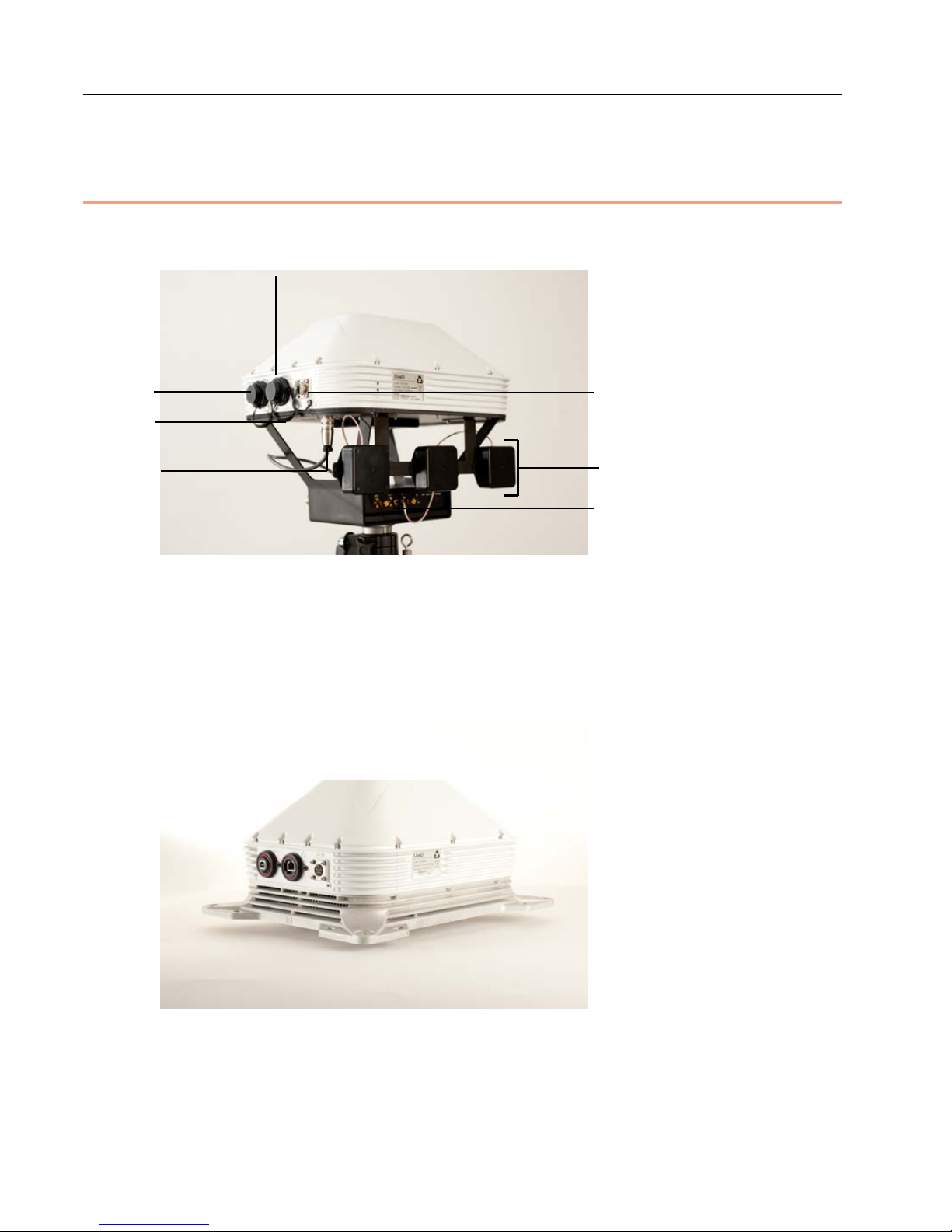
The follo wing shows the various components of th e LiveU Xtender:
LAN (Ethernet
Figure 3: LiveU Tripod Xtender
The Rooftop Xtender has the same connectors as the Tripod Xtender, shown
above. Its power is connected directly to the vehicle so that it automatically
powers on and off with the vehicle. It does not have a power butto n o r D C
OUT on the bottom.
Figure 4: LiveU Rooftop Xtender
10
Page 11
Introducing the LiveU Xtender
• LAN (Ethernet) Port: Can be connected to the Wi-Fi Client or directly to
an LU70 Ethernet port.
• USB Type B Connector (Gadget): For connec ting to the LU70 or LU40.
• DC IN: 12-volt input sour ce f o r connecting to a provided power su pply.
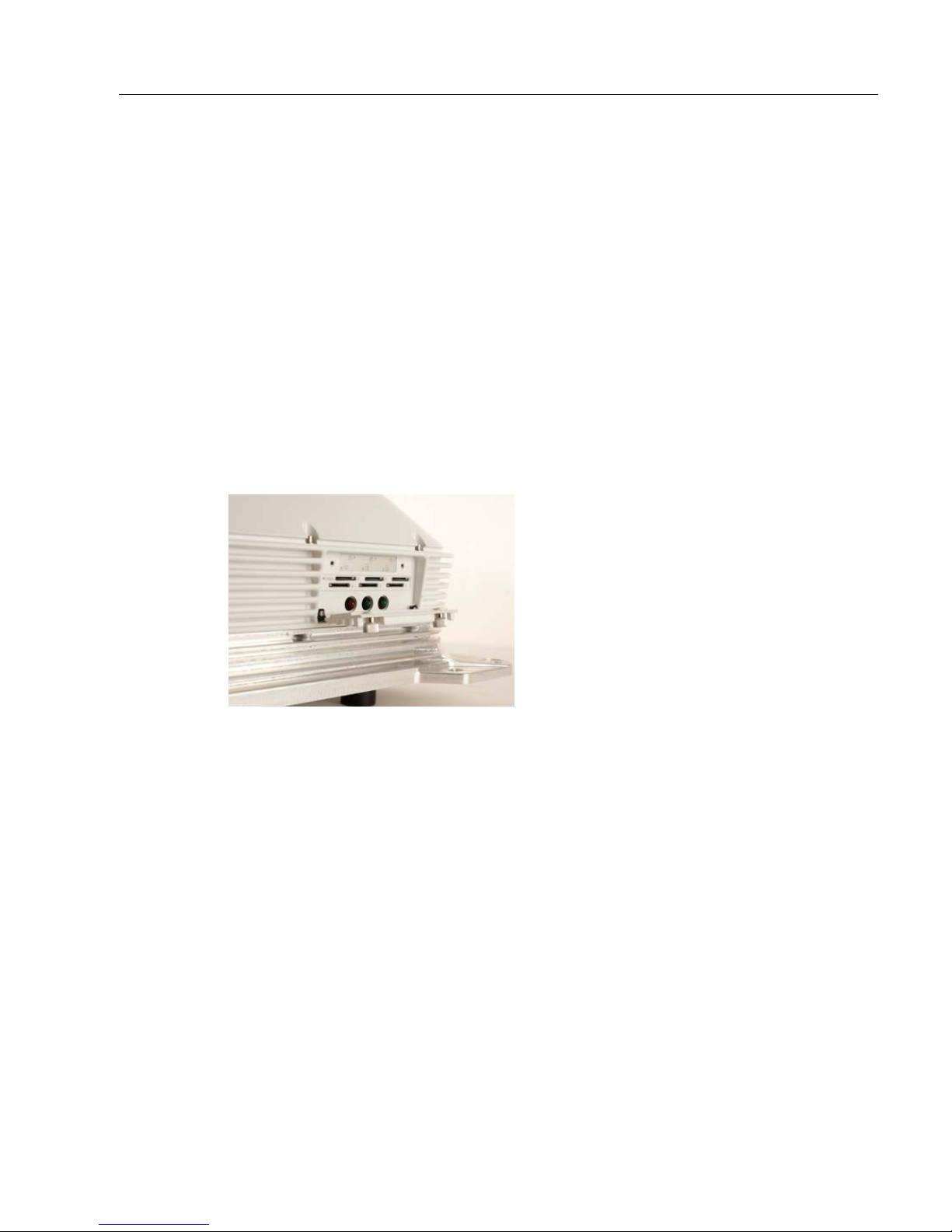
• SIM Card Slots: Six numbered slots are provided for inserting SIM cards.
Slots 1 through 4 support all 3G/4G cellular bands.
Slots 5 and 6 support high-frequently bands 1,700 – 2,600 MHz.
The SIM card slots are protected by a cove r th at unscrews to open. The
following figure shows a detailed view of the SIM card slots, as well as the
correct direction for the inser tion of these cards. Be sure to insert card s in
the correct direction.
Figure 5: SIM Card Slots
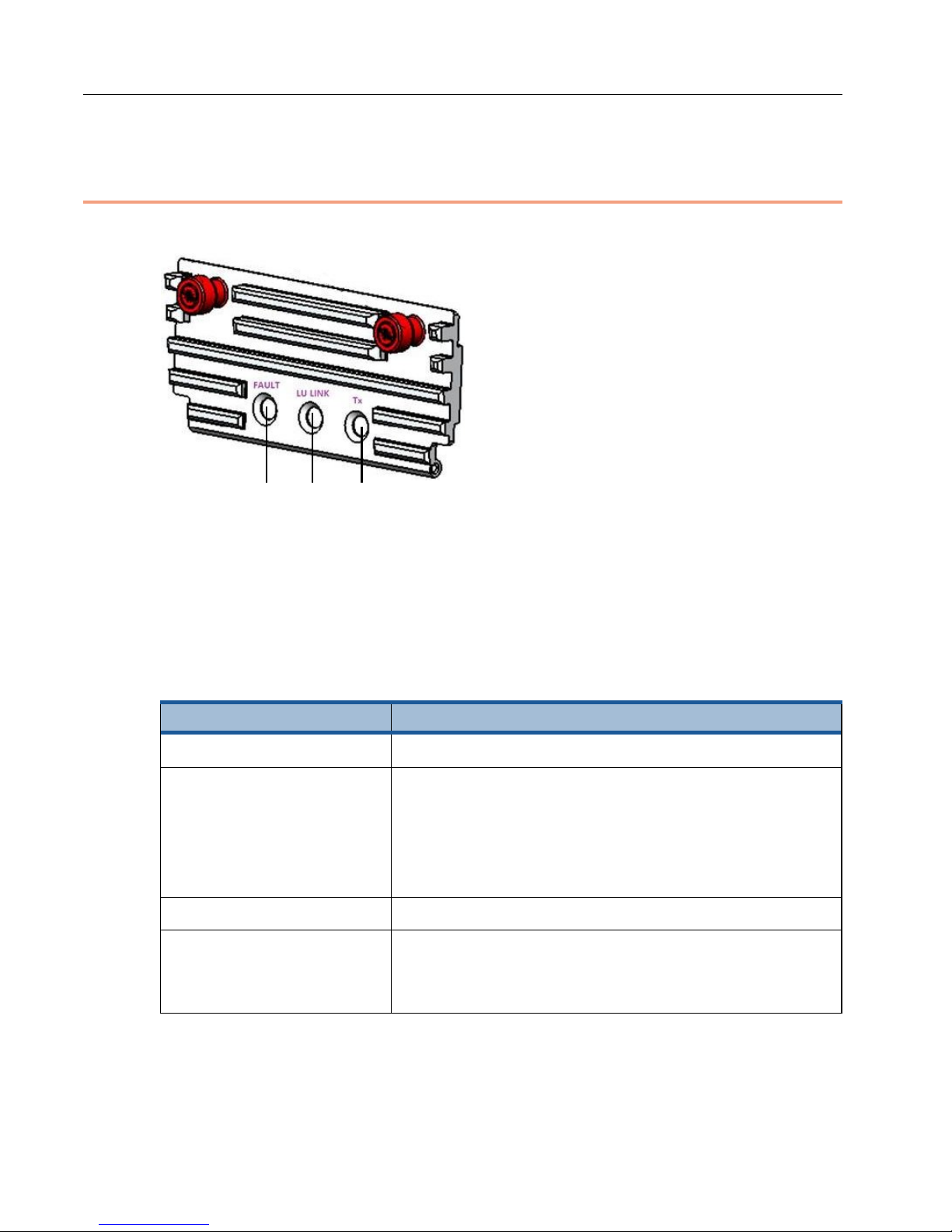
• Status LEDs: Three colored LEDs l ight up to indicate system status, such
as the link, alarm and streamin g status, as described in the Stat us LED s
section on page 12.
• Power Button (Tripod Xtender Only): To po wer ON, press and hold the
power button for approximately two seconds until it lights up. To power
OFF, press and hold the power button for approxim ately five seconds until
its light goes off.
• DC OUT: Can be used to power an external device.
• Battery Adapter: Enables the connection of an Anton Bauer or a
video-mount batte r y.
• Tripod Adapter (on th e Tripod Xtender)
11
Page 12
LiveU Xtender User Guide
Tx
LU Link
Fault
Status LEDs
The LiveU Xtender has three status LEDs, sho wn below and in Figure 5.
Figure 6: Status LEDs
Upon power up, all LEDs light for three seconds and return to normal operation
after the software loads and the unit begins to work. The following table
describes the various states of the status LEDs.
Table 2: LiveU Xtender Status LEDs
LED State Description
All LEDs are off. Powering down.
Fault LED is red. Indicates an error, such as the following:
• Battery low
• High temperature
• Fan stuck
LU Link LED is green. Local-to-remote link (via Ethernet or wireless).
Tx LED is green. Normal video transmission operation (video uplink
is operational). T his LED lights when one or more
modems are transmitting.
12
Page 13
2
LiveU Xtender Getting
Page
Page
Page
Page
Page
Page
Started
This chapter describes how to set up and get started using the LiveU Xtender.
Workflow Overview
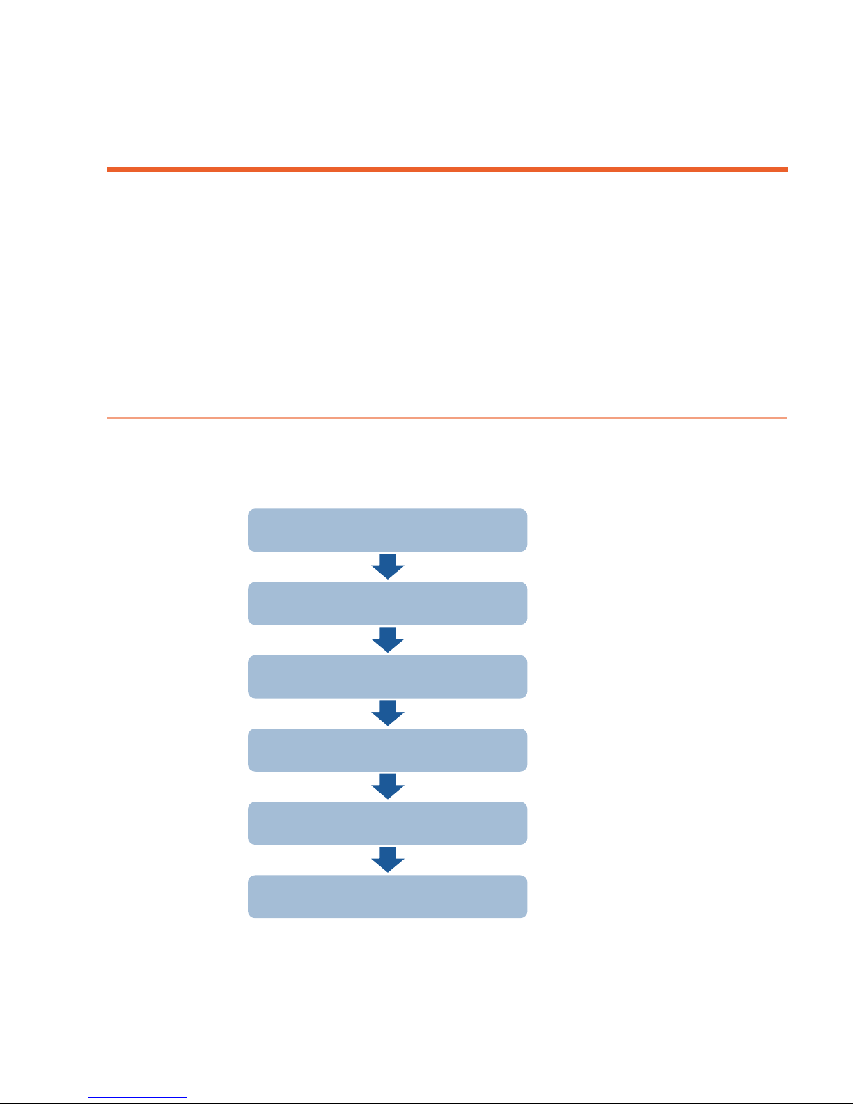
Open the LiveU Xtender suitcase and check all the contents according to the
list provided in the What’s in the Suitcase? section on page 9. The fo llowing is
a recommendation for the o r der for setting up the LiveU Xtender.
Step 1
Step 2
Step 3
Step 4
Step 5
Step 6
Figure 7: Workflow – Setting Up the LiveU Xtend er
Installing the Hardware
Connecting the LiveU
Xtender to the LU Device
Connecting the Power
Source
Turning On the LiveU
Xtender
Configuring the LiveU Xtender
Connection Type
Verifying the Connection
14
18
23
24
25
26
13
Page 14
LiveU Xtender User Guide
Front of the vehicle
Back of
the vehicle
The LiveU Xtender is supported in the LU70 software version 6.3 and up and in
the LU40 software vers ion 2.0 and up.
Step 1, Installing the Hardware
Two options are available for installing the LiveU Xtender:
• Vehicle Rooftop Installation, page 14
• Tripod Installation, page 17
Vehicle Rooftop Installation
The sections that follow descr ibe the consi derations and limitations when
installing the LiveU Xtender on a vehicle’s rooftop, including:
• Direction Considerati o ns, page 14
• Space Requirements, page 15
• Distance Bet we en Antennas, page 15
• Distance from Other Metal Bodies, page 16
Direction Considerations
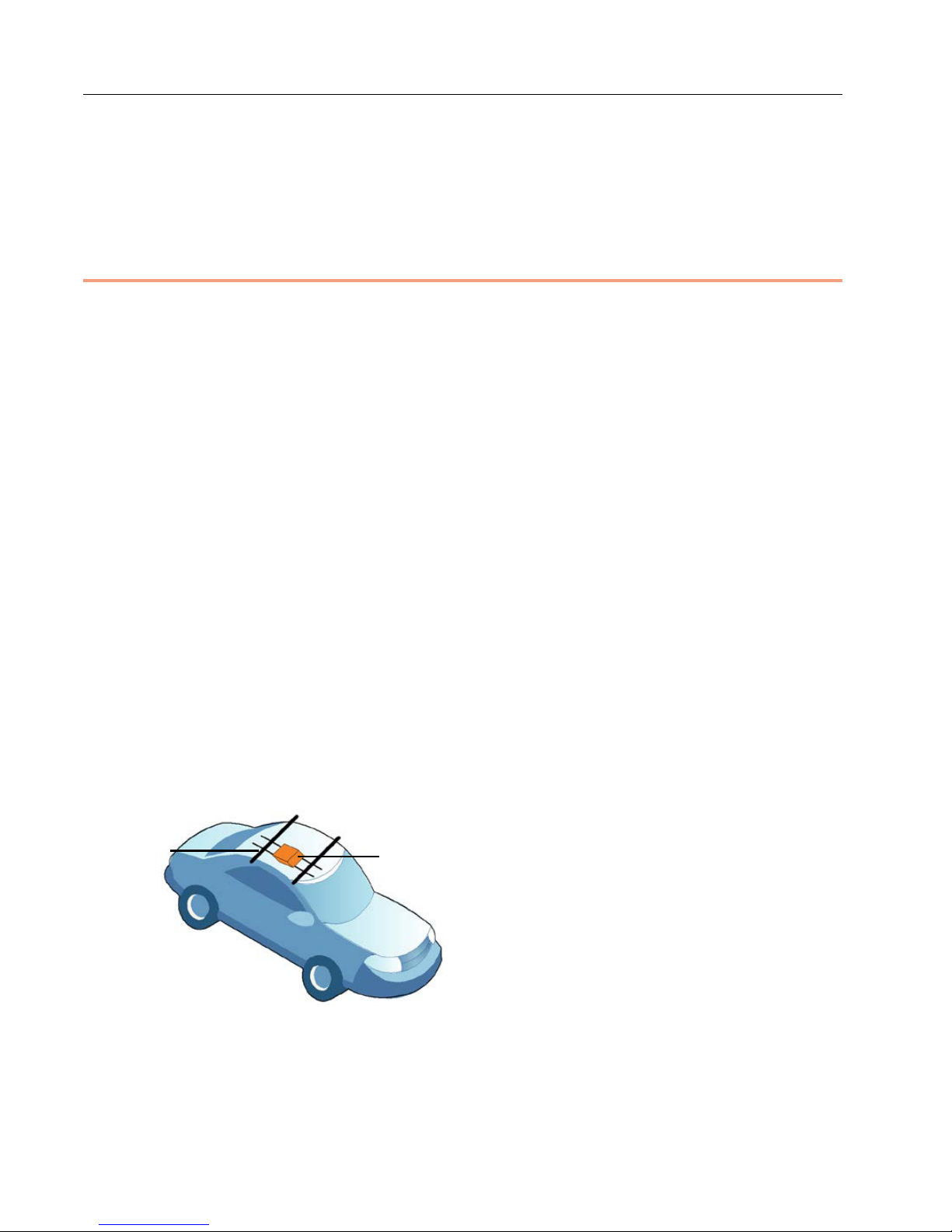
When mounting the LiveU Xtender on the vehicle, be sure to position it so that
its front is facing the front of the car and its back is facing the back of the car,
as shown below:
Figure 8: Positioning LiveU Xtender on a Vehicle Rooftop
14
Page 15
65mm MIN
Mount this side facing the
fro
Mount this side
facing
the
of
the vehicle.
back
LiveU Xtender Getting Started
Cables connected to the LiveU Xtender must be attached from its b ack in order
to improve aerodynamic effects while the car is driving.
nt of the vehicle.
Figure 9: Positioning LiveU Xtender on a Vehicle Rooftop – Cable Connections
Space Requirements
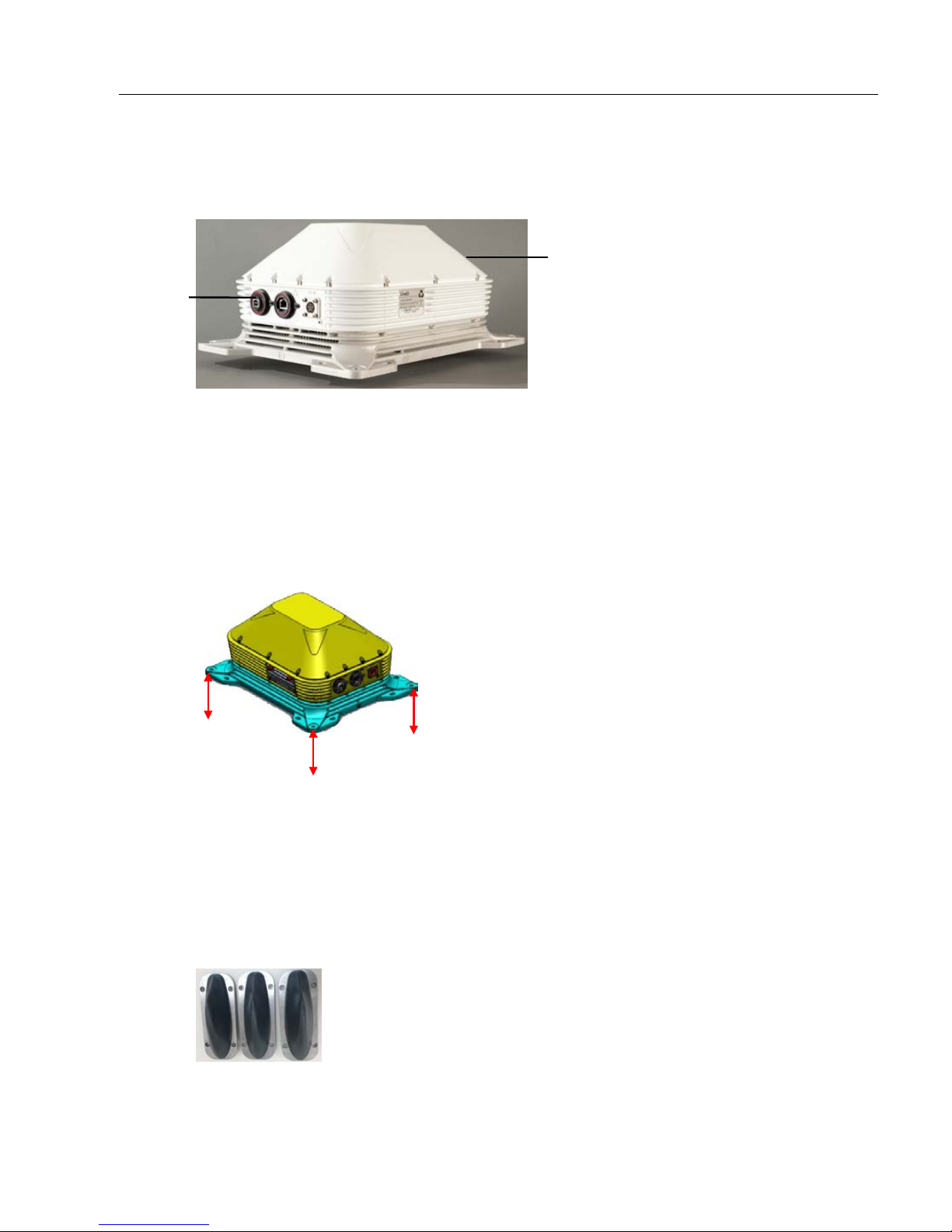
Do not attach the LiveU Xtender to the vehicle’s roof surface. A minimum of
6.5 cm must be kept between the r o o f surface and the bottom side of the
LiveU Xtender, in order to provide adequ ate int ernal air circ u la ti o n.
Figure 10: LiveU Xtender Space Requ irements – Bottom Side
Distance Between A ntenna s
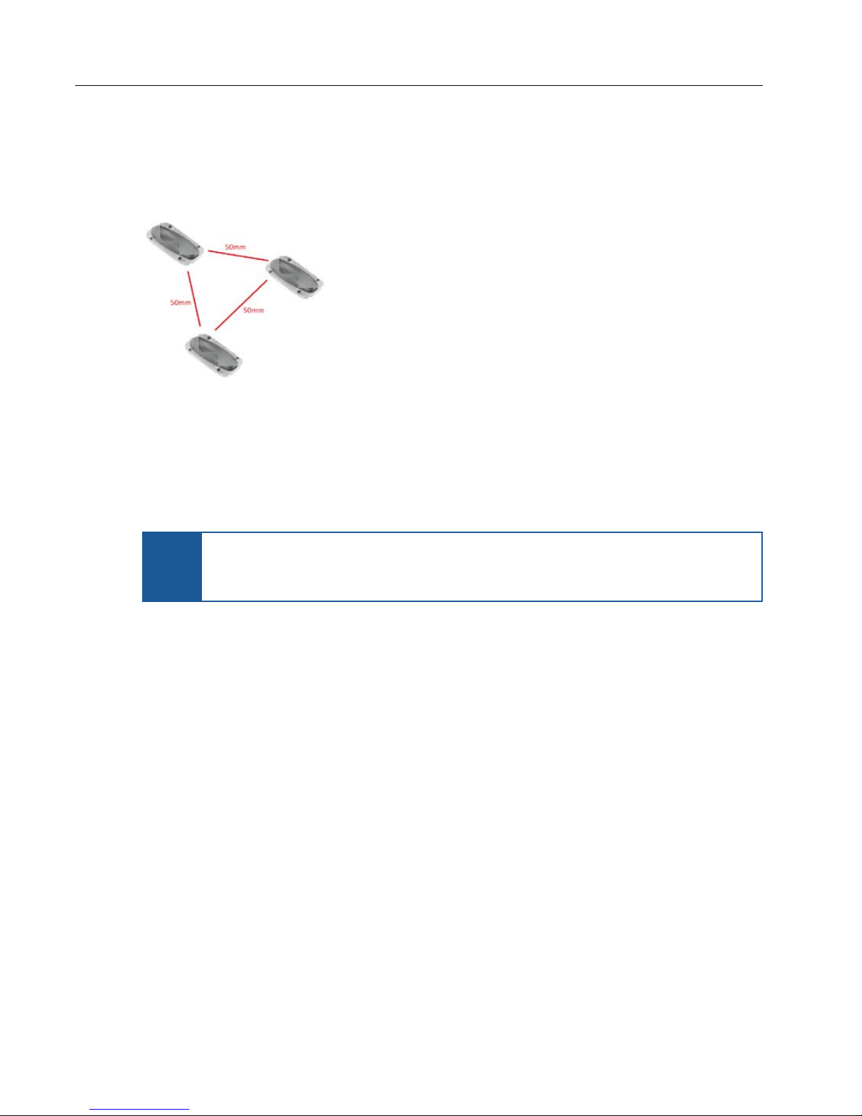
Three shark fin antennas are prov ided to be installed on the vehicle r o o f to p
together with the LiveU Xtender. These antennas connect to the Wi-Fi l in k
access point.
Figure 11: Three Shark Fin Antennas
15
Page 16
LiveU Xtender User Guide
A minimum distance of 50 mm is required between each antenna on the
vehicle roof. It is best to place the three antennas in a triangular formation on
the roof, as shown below:
Figure 12: Distance Between Antennas
Distance from Other Metal Bodies
If any additiona l metal equipment must be placed on the vehicle roof, it mu st
be at least 0.5 m from the LiveU Xtender un i t.
If additional equipment beyond the L iveU Xtender must be placed on
NOTE
the vehicle roof, it is strongly recom m ended to consult LiveU before
installing the LiveU Xtender.
16
Page 17
LiveU Xtender Getting Started
Three Antennas
Tripod Installation
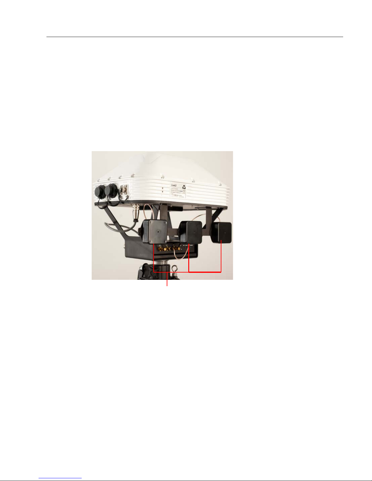
The LiveU Xtender has a standard tr ipod connector on its bottom.
► To mount the LiveU Xtender:
1 Mount the LiveU Xtender usin g its tripod adapter.
2 Screw the three directional antennas onto the bar attached to the LiveU
Xtender, as shown below:
Figure 13: Mounting the Three Directional Antennas
17
Page 18
LiveU Xtender User Guide
Rooftop
Tripod
LU40
LAN Ports
Step 2, Connecting the LiveU Xtender to
the LU Device
The following describes how to connect the LiveU LU40 and LU70 unit to the
LiveU Xtender. The following three connection options are available:
• LAN Connection, page 18
• USB Connection (Onl y for the LU7 0), page 19
• Wi-Fi Connection, page 20
LAN Connection
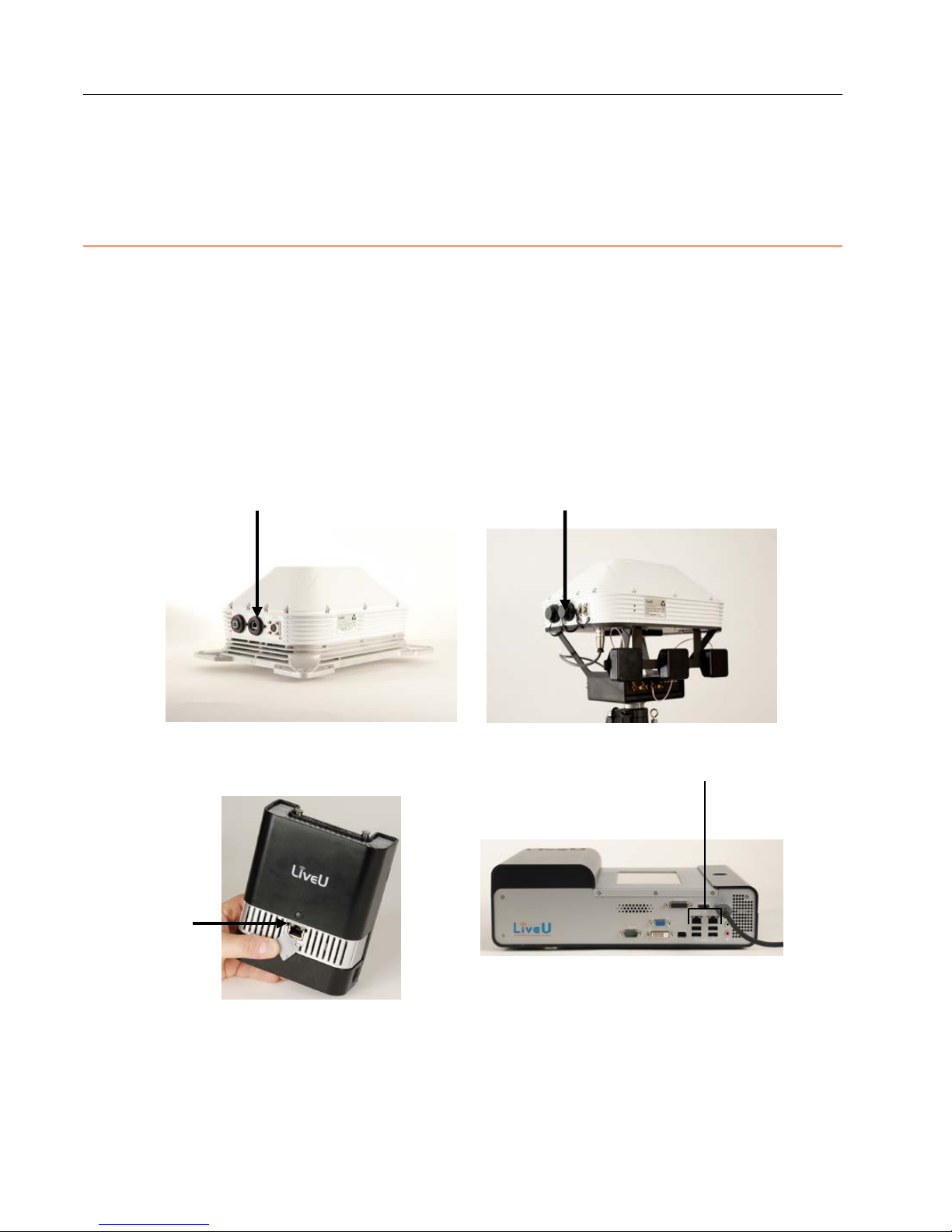
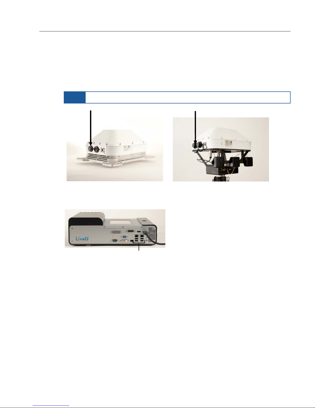
Both the LU70 and the LU40 can be connected directly to the LiveU Xtender
via their LAN (Ethernet) port, as described below.
Figure 14: LiveU Xtender LAN (Ethernet) Port
LU70
Figure 15: LU40 and LU70 LAN (Ethernet) Ports
On the back of the LU40, gently move the white plastic covering the Eth ernet
port to the side and plug in the Ethernet cable.
18
Page 19
LiveU Xtender Getting Started
Rooftop
Tripod
Four USB Ports
USB Connection
The LU70 can be connected directly to the LiveU Xtender via one of its four
USB ports, as described below.
NOTE
The LiveU LU40 does not connect to the LiveU Xtender via USB.
Figure 16: LiveU Xtender USB Port
Figure 17: LU70 USB Ports
19
Page 20
LiveU Xtender User Guide
CBL00173 75cm
CBL00173 75
cm
CBL00173 75cm
RT Access Point
65mm MIN
60mm MIN
AC/DC CBL00131 120cm
AC/DC CBL00131
120cm
Power Source
LAN CBL00132 100cm
60mm MIN
Car Roof
Wi-Fi Antennas
LiveU Xten der
Wi-Fi Access Point
Wi-Fi Connection
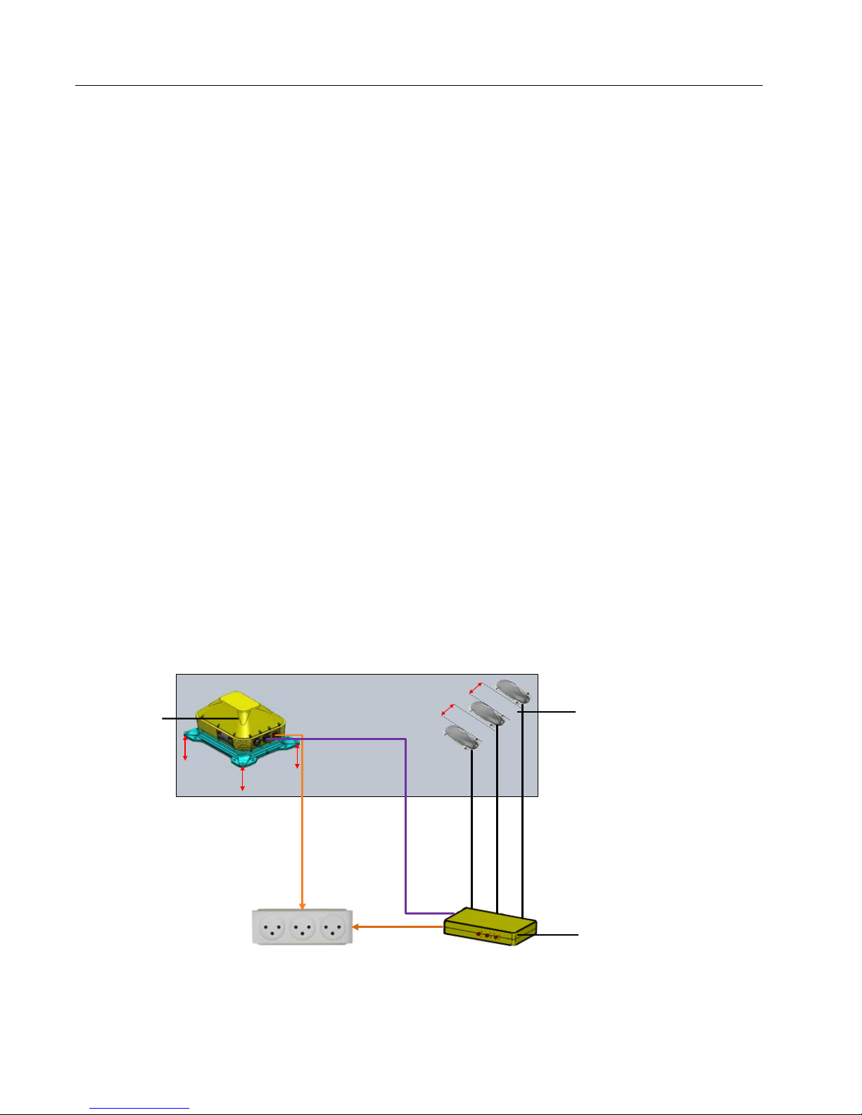
The following is a summary of the connections for Wi-Fi communication
between the LU740/LU40 and the LiveU Xtender via Wi-Fi:
• LiveU Xtender connects to Wi-Fi Access Point via LAN cable. The
LAN (Ethernet) ports of the LiveU Xtender are shown in Figure 14.
• Wi-Fi Access Point has Wi-Fi antennas that communicate with the
antennas of the Wi-Fi Client.
• Wi-Fi Client has Wi-Fi antennas that communicate with the antennas of
the Wi-Fi Access Point.
• LU40/LU70 connects to Wi-Fi Client via LAN cable. The LAN
(Ethernet) ports of the LU70 and LU40 are shown in Figure 15.
► To set up the LiveU Xtender Wi-Fi con nection:
Mounte d on
Vehicle Rooftop
1 Connect the Wi-Fi Access Point’s three antennas to three RF ports on the
Wi-Fi Access Point.
2 Connect the LiveU Xtender to the Wi-Fi Access Point via LAN cable. The
LAN (Ethernet) ports of the LiveU Xtender are shown in Figure 14.
The follo wing figure illustrates t he Wi-Fi connectio n between the LiveU
Xtender and the Wi-Fi Access Point.
Figure 18: LiveU Xtender to Wi-Fi Access Point Connection
20
Page 21
LiveU Xtender Getting Started
CBL00191 60cm
Power Source
CBL00191 60cm
CBL00190 24cm
LAN CBL00162 40cm
ANT00011
ANT00011
ANT00010
DC Cable (x
3 USB) CBL00158
Ext Charger to
Remote Antenna
Kit Power
CBL00161 60cm
DC Cable
CBL00131
120cm
Ext Battery
CBL00161
60cm
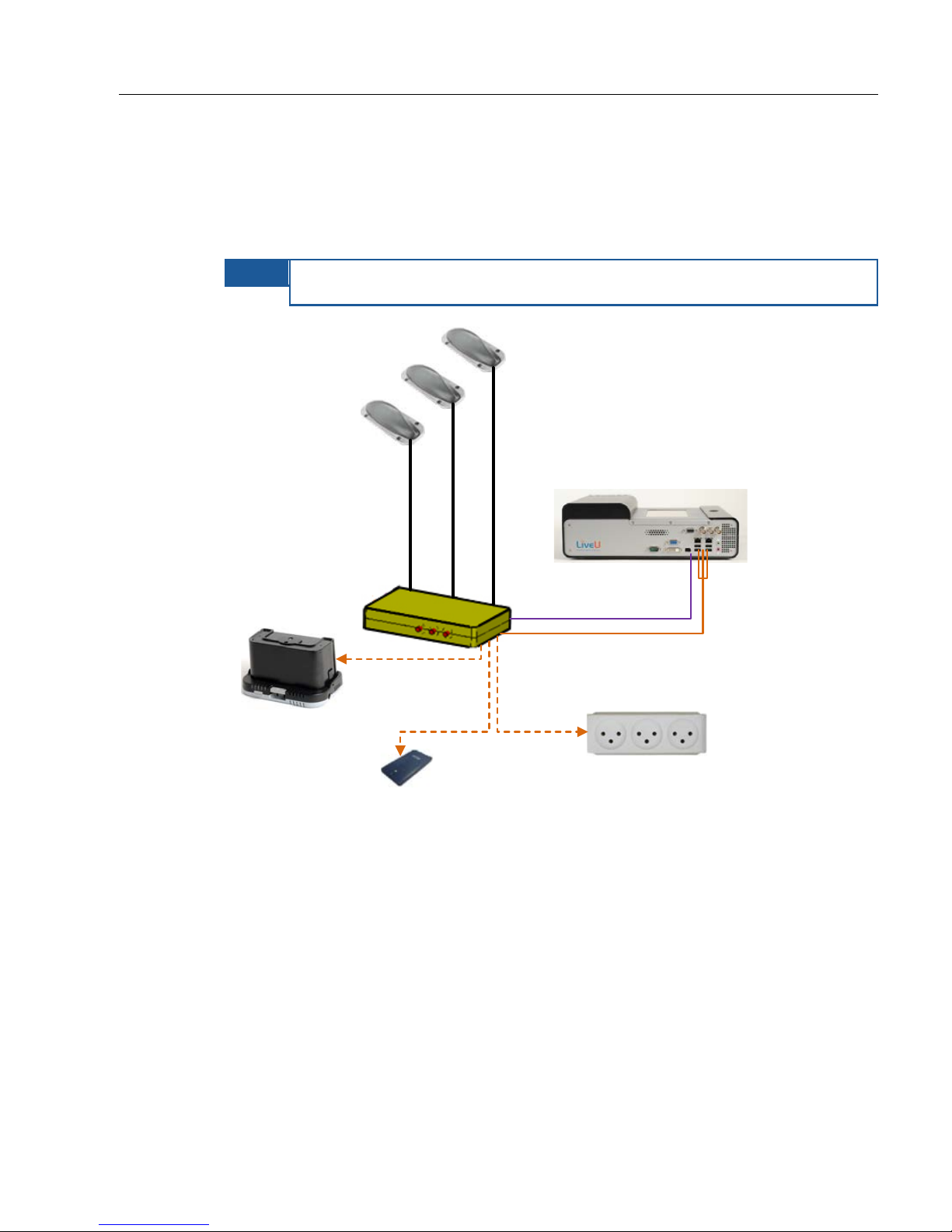
3 Connect the LU70/LU40 t o th e Wi-Fi Client via LAN cable. The LAN
(Ethernet) ports of the LU units are shown in Figure 15.
The follo wing figure illustrates t he Wi-Fi connectio n between the
LU70/LU40 and the Wi-Fi Client.
NOTE
The LU70 must only be connected via the LAN1 port.
Figure 19: LU70/LU40 Connectivity
21
Page 22
LiveU Xtender User Guide
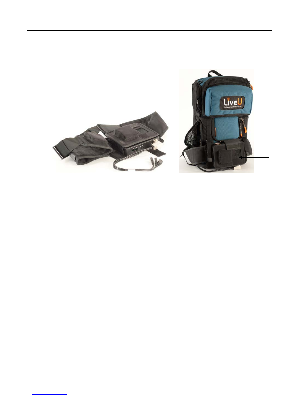
The LU70 backpack inc ludes a belt that can be wo rn by the operator. This belt
has three antennas mounted on it.
Belt Belt on LU70 Backpack
Figure 20: Wi-Fi Client Belt
22
Page 23

LiveU Xtender Getting Started
Step 3, Connecting the Power So urc e
The LiveU Xtender can operate with a standard An ton Bauer or a video-mount
battery (not provide d) or using the provided 12-volt power supply that
connects to any standard 110VAC / 220VAC power source.
The LiveU Xtender does not charge the battery.
Both the provided powe r su pply and the battery can be connected at t h e same
time. When the power supply is plugged into a power source, the LiveU
Xtender uses the power supply and the battery’s power is not used. When the
power supply is not plugged in, the battery automatically takes over.
The Rooftop LiveU Xtender can be connected to the vehicle’s power.
► To connect the power source for the Rooftop Xtender:
• Connect the battery to the LiveU Xtender’s battery adapter.
And/Or
• Connect the DC IN connector of the Rooftop LiveU Xtender to the vehicle.
► To connect the power source for the Tripod Xtender:
• Connect the battery to the LiveU Xtender’s battery adapter.
And/Or
• Connect the LiveU Xtender’s power supply to the DC IN connector, as
shown in Figure 3.
If the LiveU Xtender is connected via Wi-Fi to the LU device, then yo u must
also provide a power source for the Wi-Fi Access Point and the Wi-Fi Client, as
described below.
► To connect Wi-Fi Access Point and Wi -Fi Client power:
1 Connect power to the Wi-Fi Client by:
Connecting it directly to a power source.
Connecting it to an external battery.
23
Page 24
LiveU Xtender User Guide
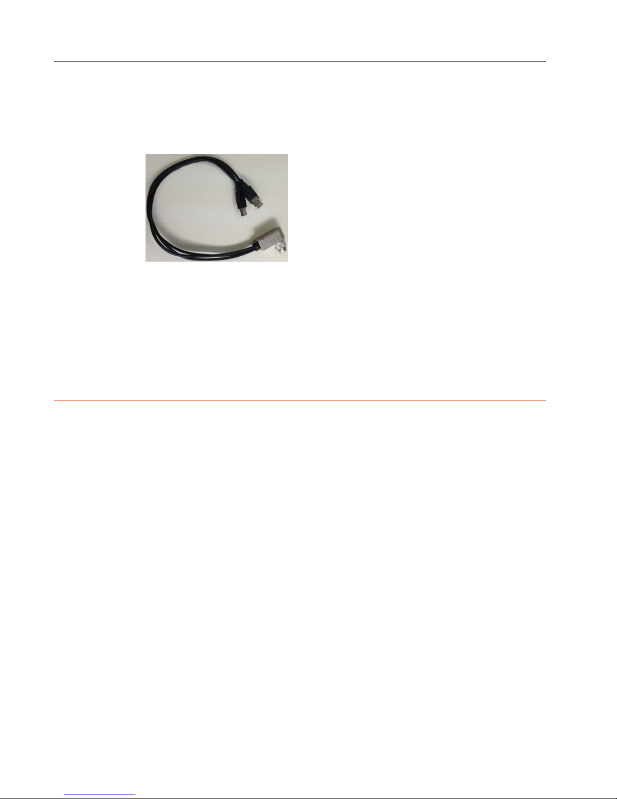
Using the special provided USB cable (shown below) to connect power
from the LU70 to the Wi-Fi c lient. All three U SB connectors must be
connected to the LU70. The LU40 does not have this option.
Figure 21: Wi-Fi Client-to-LU70 USB Power Cable
2 Connect power to the Wi-Fi Access Point either by:
Connecting it d irectly to a power source (for exam ple, in the vehicle).
Connecting it to an external battery.
Step 4, Tur ning On the LiveU Xt ender
► To power on the LiveU Xtender:
• For a Tripod Xtender, pr es s and hold the power button for approximately
two seconds until it lights u p.
• The Rooftop Xtender automaticall y powers o n and off with the vehicle. It
does not have a power button.
Turning Off the LiveU Xtender
After transmission has been stopped on all LU units in the area, you can power
off the LiveU Xtender.
► To power off:
• For a Tripod Xtender, pr es s and hold the power button for approximately
five seconds until its light goes of f.
• The Rooftop Xtender automatically powers on and off with the vehicle. It
does not have a power button.
24
Page 25
LiveU Xtender Getting Started
Step 5, Configuring the LiveU Xtender
Connection Type
This step describes how to specify the method used for connecting the LiveU
Xtender to the LU unit: Wi-Fi, LAN or USB.
► To configure the LiveU Xtender type:
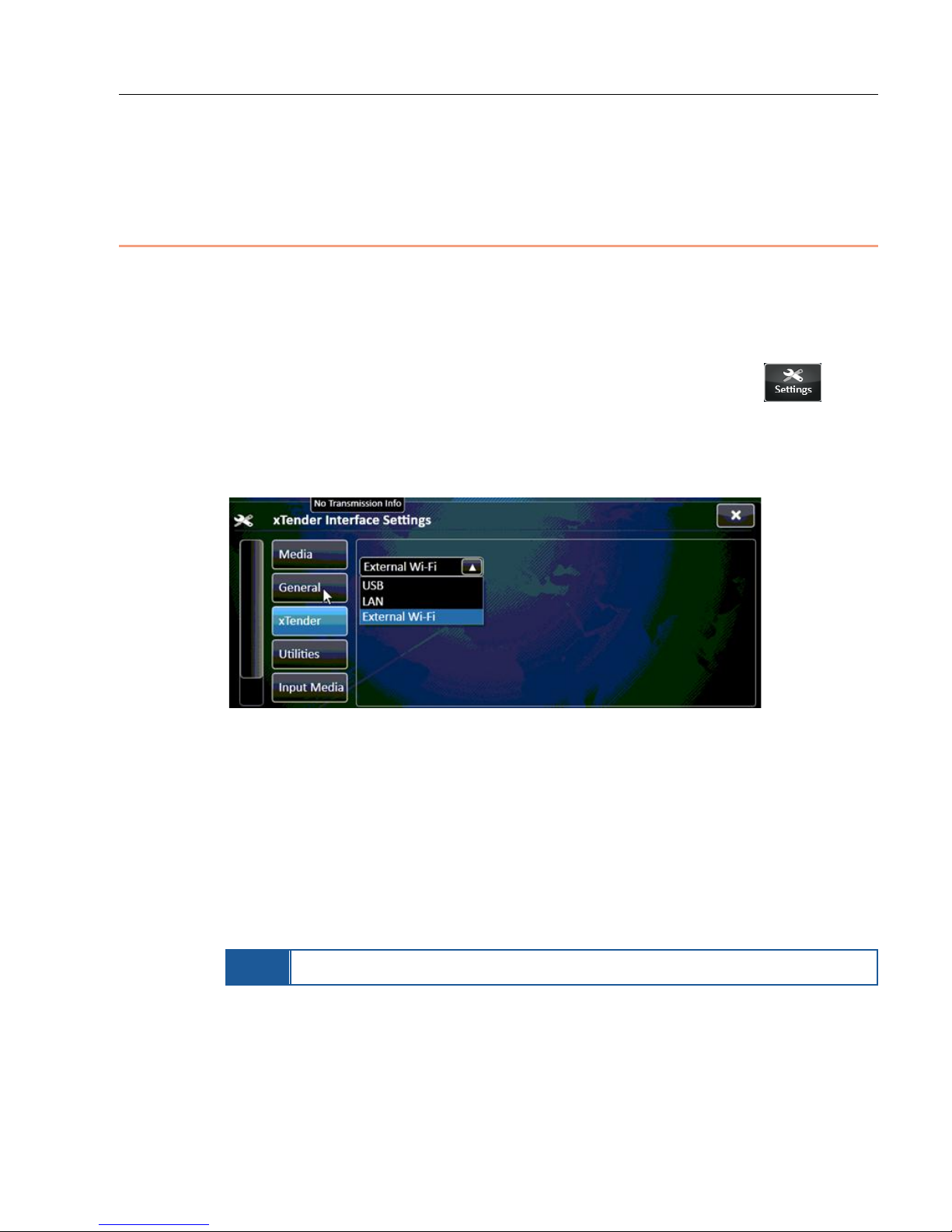
• Display the Xtender Settings window by tapping the Settings
button and then the xTender tab.
• In the xTender Interface Settings window, shown below, select the type of
connection between the LU unit and the LiveU Xtender.
Figure 22: Xtender Interface Settings Window
The options are:
LAN: Th e LiveU Xtender is connected to the LU 70/LU40 via a dir ect
LAN connection.
USB: The LiveU Xt en der is connected to the LU70/LU40 via a direct
USB connection.
External Wi-Fi: The LiveU Xtender is connected to the LU70/LU40 via
an external Wi-Fi conn ection.
NOTE
No reset is needed when specifying this setting.
25
Page 26
LiveU Xtender User Guide
Step 6, Verifying the Connection
This step describes how to verify the connection between the L iveU Xten der
and the LU unit.
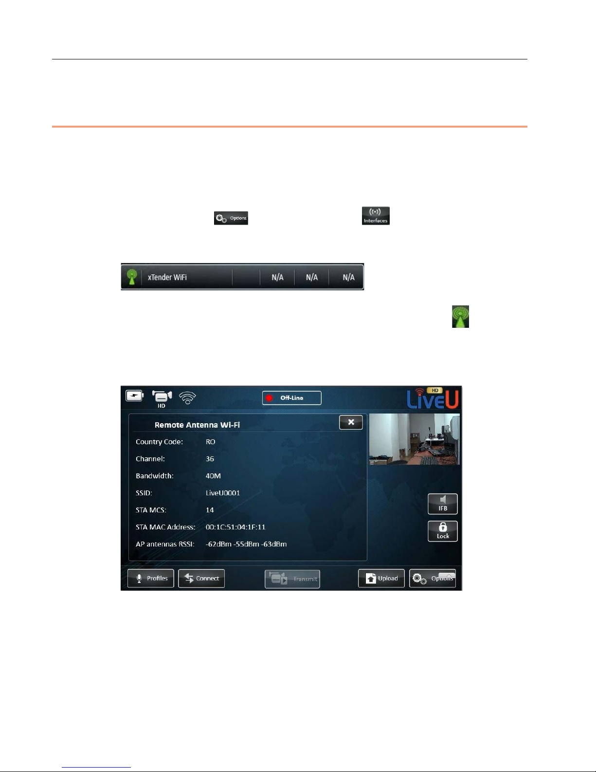
► To verify the connection on the LU70 :
1 Click the Option button and then the Interfaces button in
order to check that the LiveU Xtender appears in the Interfaces w in dow of
the LU unit device, as shown below:
Figure 23: xTender WiFi Link
The LiveU Xtender appears in the Interfaces window with the icon.
2 Tap the xTender WiFi interface in the Interfaces window, as shown below.
The follo wing window is displayed:
Figure 24: Remote Antenna Wi-Fi ‒ Xtender
26
Page 27
LiveU Xtender Getting Started
The follo wing inf ormation is displayed in th is window:
Country Cod e: Th is value is set in production according to the country
or continent to which the unit was delivered.
Channel: The 802.11n frequency channel currently in use.
Bandwidth: The use d bandwidth, whic h is the m a ximum possible,
according to the specified Country Code.
SSID: The Stat ion SSID number, w hich is a unique number that is
used to match between the tw o Wi-Fi link components (Clien t and
Access Point).
STA MCS: The Station Modulation and Coding Scheme according to the
802.11n standard.
STA MAC Address: Th e Wi-F i link’s MAC address.
AP antenna RSSI: The RX power values of the Wi-Fi link for its three
antennas.
NOTE
NOTE
If the LiveU Xtender is unidentified, contact LiveU support for
further assistance to perfor m a software upgrade.
The LU40 software version 2.0 supports the LiveU Xtender.
27
Page 28

LiveU Xtender User Guide
Blank page for double-sided printing
28
Page 29

A
Limitation of Liability and
Warranty
This appendix provides the limitations on liability and warranty.
Limitation of Liability and Warranty
This LiveU product is provided “as is” without warranty of any kind. The
company disclaims all other warranties, either express or implied, including
but not limited to implied warr anties of merchantability and fitnes s f o r a
particular purpose an d non-infringement.
Under no circumstances shall the company be liable for any d amages
whatsoever (including, without l i mitation , consequential, special, or inci dental
damages, or damages for loss of bus iness profits, business interrupt ions, loss
of business information or other pecuniary loss) arising out of the use of or
inability to use the LiveU product, even if the company has been advised of
the possibility of such damages.
29
Page 30

LiveU Xtender User Guide
Blank page for double-sided printing
30
Page 31

B
FCC Compliance
Statement
This appendix prov ides the FCC compliance information.
Note: This equipme n t has been tested and found to comply with the limits for
a Class B digital device, pursuant to part 15 of the FCC Rules. These limits are
designed to provide reasonable protection against harmful interference in a
residenti al installation. This equipment generates, uses and can radiate radio
frequency energy and, if not installed and used in accordance with the
instructions, may cause harmful interference to radio communications.
However, there is no guarantee that interference will not occur in a particular
installation. If this equipm en t doe s cause harmful interference to r adio or
television reception, which can be determined by turning the equipment off
and on, the user is encouraged to try to correct the interference by one or
more of the following measures:
• Reorient or relocate the receiving antenna.
• Increase the separation between the equipm ent and receiver.
• Connect the equipment into an outlet on a circuit different from tha t to
which the receiver is connected.
• Consult the dealer or a n experie nced rad i o/TV technicia n for help.
Modifications not expressly approved by the manufacturer could void the
user's authority to operate the equipment under FCC rules.
This device complies with part 15 of the FCC Rules. Operation is subj ect to the
following two conditions:
• This device may not cause harmful interference.
• This device must accept any interference rece ived, including interference
that may cause undesire d operation.
31
Page 32

US and International:
2 University Plaza Drive
Suite 505
Hackensack, New Jersey, 07601
USA
Tel: 1
Fax: 1
USA and the Americas:
[email protected]
International:
-(201)-742-5228
-(201)-623-4838
 Loading...