

Livestrong Matrix 2010 SB LS User Manual
S-SERIES
LIVESTRONG S-series
Model no. 2010 SB LS
Manufactured by:
Indoorcycling Group GmbH
Happurger Str. 84-88
90482 Nuremberg | Germany
www.indoorcycling.com
info@indoorcycling.com
MATRIX Fitness Systems Corp.
1610 Landmark Drive
Cottage Grove, WI 53527
Toll-free: 866.693.4863
Local: 608.839.8686
www.matrixtness.com
CAUTION !
Read all precautions and instructions in this manual before using this equipment. Keep this manual
for future reference.
Improper assembly, maintenance or use can void the warranty terms.
Version 1.1 2010 SBLS Copyright by Indoorcycling Group GmbH 2010 | www.indoorcycling.com ENG 1
ENG ESP

S-SERIES
TABLE OF CONTENTS
Important precautions page 3
Before you begin page 4
How to assemble the LIVESTRONG S-Series Indoor Cycle page 5-7
Wireless Onboard Computer & part list page 8-9
Channel Setting & battery installation page 10-11
Transmitter & computer assembly page 12-13
Signal distribution of heart rate & cadence page 14
Technical specications & features page 15
Before you start & how to operate page 16-18
Initial install checks page 19
How to adjust the LIVESTRONG S-Series Indoor Cycle page 20
Pedal strap adjustment page 20
Saddle height adjustment page 20
Saddle horizontal adjustment page 21
Handlebar adjustment page 22
Resistance adjustment page 23
How to move the LIVESTRONG S-Series Indoor Cycle page 23
Preventative maintenance page 24
Daily maintenance page 24
Weekly maintenance page 24
Bi-Weekly maintenance page 25
Monthly maintenance page 26-27
Belt drive system page 28
Maintenance activity plan & check lists page 29-30
Explosion drawings of structural components page 31-36
Spare part reference list page 37
Limited warranty page 38
Technical specications:
The LIVESTRONG S-Series Bike is according to EN 957 a Class S product for professional
and / or commercial use. Such training equipment is intended for the use in training areas
of organizations such as tness clubs or sport associations, where access and control is
specially regulated by the person who has the legal responsibility.
Foot print: 55 x 115 cm / 21.7 x 45.3 inch
Weight of bike: 51 kg / 113 lbs
Max saddle height: 115 cm / 45.3 inch
Max handlebar height: 115 cm / 45.3 inch
Max user weight: 130 kg / 287 lbs
The Bike is designed to accommodate most users from 150 to 205 cm / 59.1 to 81.7 inch
body height.
Version 1.1 2010 SBLS Copyright by Indoorcycling Group GmbH 2010 | www.indoorcycling.com ENG 2

IMPORTANT PRECAUTIONS
WARNING!
To reduce the risk of serious injury, read the following important precautions and information before
operating the LIVESTRONG S-Series Indoor Cycle.
It is the responsibility of the owner to ensure that all users of the LIVESTRONG S-Series Indoor
1.
Cycle are informed of all warnings and precautions.
Operate and maintain the LIVESTRONG S-Series Indoor Cycle only as described in this manual.
2.
Do not operate the LIVESTRONG S-Series Indoor Cycle until it is properly assembled (see page
3.
5-8).
Keep the bike indoors, away from moisture and dust. Do not place the LIVESTRONG S-Series
4.
Indoor Cycle in a garage or covered patio or near water.
Place the LIVESTRONG S-Series Indoor Cycle on a level surface. To protect the oor or carpet
5.
from damage, place a mat beneath the LIVESTRONG S-Series Indoor Cycle. Make sure that
there is adequate room around the LIVESTRONG S-Series Indoor Cycle to mount, dismount,
and operate it.
Regularly inspect and properly tighten all parts of the LIVESTRONG S-Series Indoor Cycle as
6.
recommended in this manual. Please replace defective parts immediately and do not use the
bike until repair is performed. Only use original parts from the manufacturer.
Children under the age of 14 should only be allowed use of the LIVESTRONG S-Series Indoor
7.
Cycle with parental consent and guided by a specially trained instructor.
The LIVESTRONG S-Series Indoor Cycle should not be used by persons weighing more than
8.
290 pounds (130 kg).
Always wear appropriate athletic clothes and shoes while operating the LIVESTRONG S-Series
9.
Indoor Cycle. Do not wear loose clothes that could become caught on the LIVESTRONG SSeries Indoor Cycle or shoes with loose laces.
Before using the LIVESTRONG S-Series Indoor Cycle, make sure that you are familiar with the
10.
operation of the Indoor Cycle (see pages 8-11).
The LIVESTRONG S-Series Indoor Cycle does not have an independently moving ywheel
11.
(wheel); the pedals will continue to move together with the ywheel until the ywheel stops.
Always regulate the ywheel resistance so that your pedalling motion is controlled (see page 11).
12.
Keep your back straight while using the LIVESTRONG S-Series Indoor Cycle; do not arch your
13.
back.
If you feel pain or dizziness while exercising, stop immediately, rest and cool down.
14.
If replacement parts are needed, use only manufacturer supplied parts.
15.
WARNING:
Before beginning any exercise program, consult your physician. This is especially important for
persons over the age of 35 or persons with pre-existing health problems. Read all instructions before
using. Be aware that incorrect or extensive training may result in serious health injuries. The
manufacturer assumes no responsibility for personal injury or property damage sustained by or
through the use of this product.
ENG ESP
Version 1.1 2010 SBLS Copyright by Indoorcycling Group GmbH 2010 | www.indoorcycling.com ENG 3
BEFORE YOU BEGIN
Dear Customer,
Congratulations for selecting the LIVESTRONG S-Series Indoor Cycle.
The LIVESTRONG S-Series Indoor Cycle offers an impressive array of features
designed to enhance cardiovascular tness, tone muscles, and develop endurance.
Whether users are beginners or experienced athletes, the LIVESTRONG S-Series Indoor
Cycle offers workouts that will help users to reach their individual tness goals.
IMPORTANT: Read this manual carefully before assembling or using the LIVESTRONG
S-Series Indoor Cycle.
If you have questions after reading this manual, please contact Indoorcycling Group GmbH
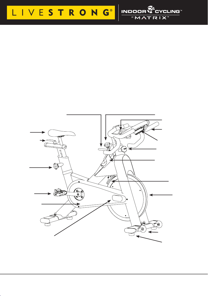
or refer to the website www.indoorcycling.com. Before reading further, please familiarize
yourself with the parts that are labeled in the drawing below.
Emergency brake handle
Resistance knob
Lever handle
Saddle
LX7 handlebar
Wireless Onboard
Lever handle
Computer
Adjustment knob
Adjustment
Dual bottle holder
knob
Brake pad
Combi
pedal
ywheel
Chain guard
Maintenance cover
Transport wheel
Levelling feet
You will nd the production code on the left side of the LIVESTRONG S-Series Indoor
Cycles within the lower range of the frame. Please refer to these in servicing and maintenance lists.
Version 1.1 2010 SBLS Copyright by Indoorcycling Group GmbH 2010 | www.indoorcycling.com ENG 4
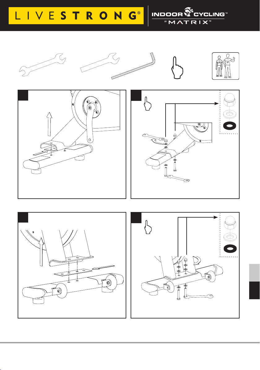
HOW TO ASSEMBLE LIVESTRONG S-Series Indoor Cycle
2x
SW 17mm
SW 14mm
1x
15mm Pedal
Wrench
1
Assure that plastic gasket is placed between
stabilizer and frame.
3
3mm
hand tight
2
Assure that black rubber washer is placed
between upper frame and bolt/washer.
4
Assure that plastic gasket is placed between
stabilizer and frame.
Please assure that nuts are tightened with signicant strength to minimize loosening during use.
Version 1.1 2010 SBLS Copyright by Indoorcycling Group GmbH 2010 | www.indoorcycling.com ENG 5
Assure that black rubber washer is placed
between upper frame and bolt/washer.
ENG ESP
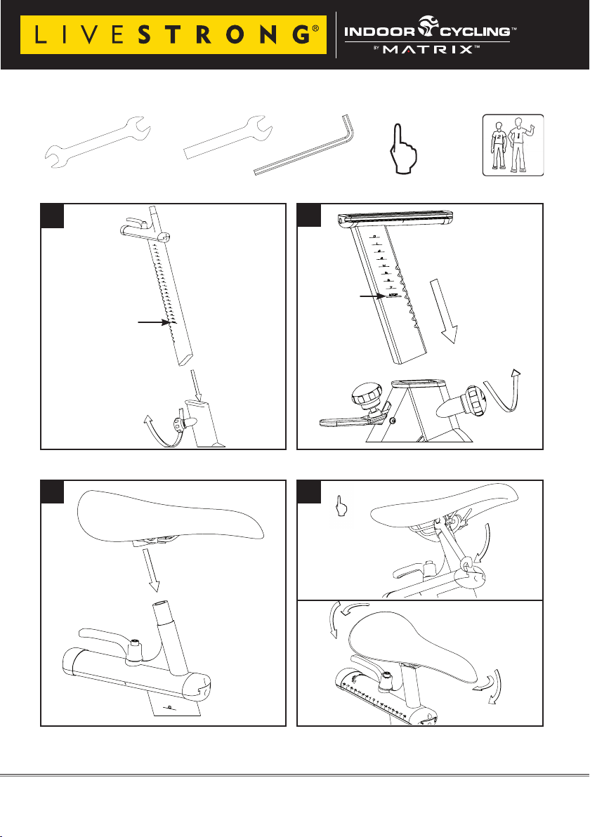
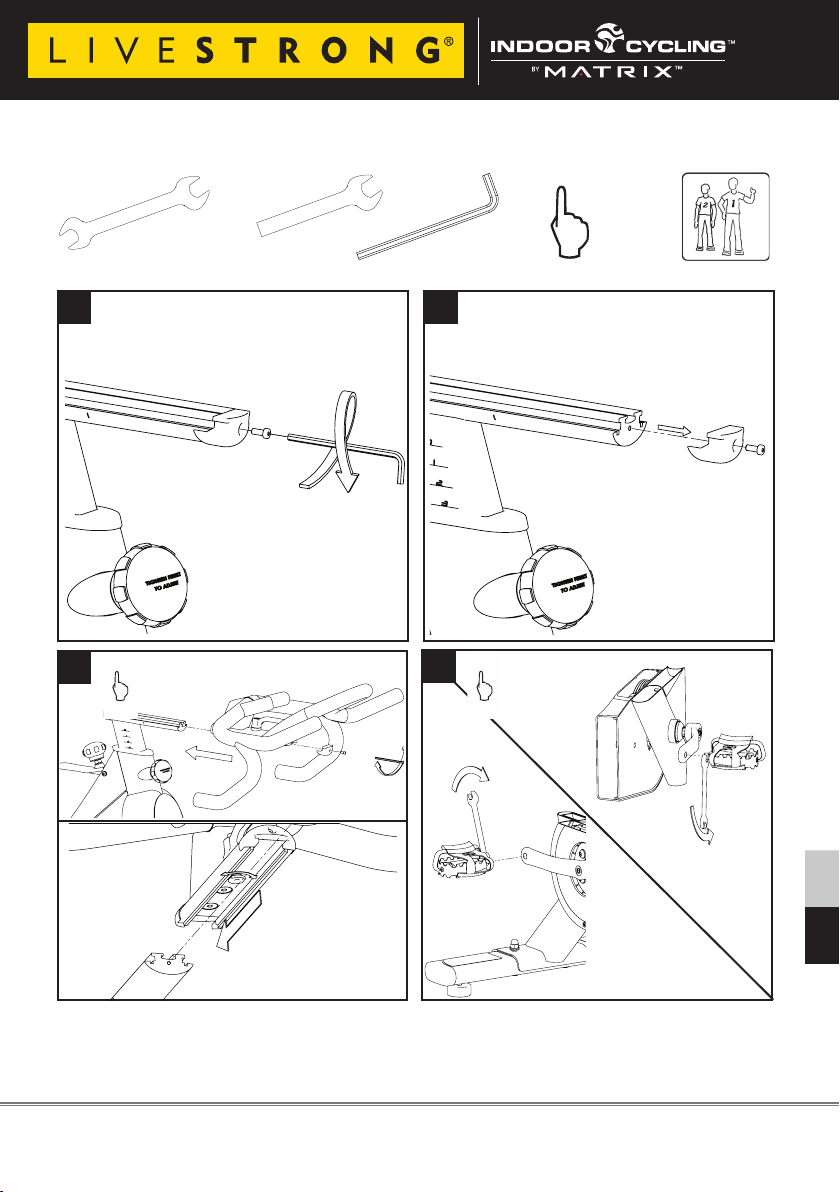
HOW TO ASSEMBLE LIVESTRONG S-Series Indoor Cycle
2x
5
STOP mark
7
SW 17mm
SW 14mm
1x
15mm Pedal
Wrench
6
STOP mark
8
3mm
hand tight
14mm
Make sure the seat
is xed properly in a
LEVEL HORIZONTAL
position
Seat clamp must be tightened securely to minimize loosening during use.
Version 1.1 2010 SBLS Copyright by Indoorcycling Group GmbH 2010 | www.indoorcycling.com ENG 6
HOW TO ASSEMBLE LIVESTRONG S-Series Indoor Cycle
2x
SW 17mm
SW 14mm
1x
15mm Pedal
Wrench
9 10
11
12
3mm
hand tight
Pedal marked R installed on right crank (clockwise), Pedal marked L installed on left crank (counterclockwise).
Pedals must be fastened with signicant strength to avoid loosening with use of the indoor cycle.
Version 1.1 2010 SBLS Copyright by Indoorcycling Group GmbH 2010 | www.indoorcycling.com ENG 7
ENG ESP
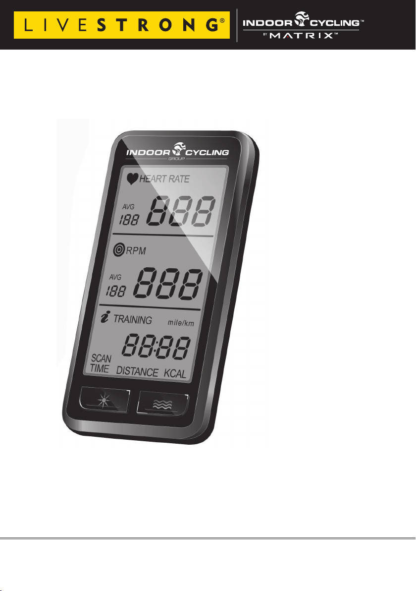
Wireless Commercial Computer - PRO 1.0
Article no. ST02 01 20
Article no. 02 01 20
Version 1.1 2010 SBLS Copyright by Indoorcycling Group GmbH 2010 | www.indoorcycling.com ENG 8
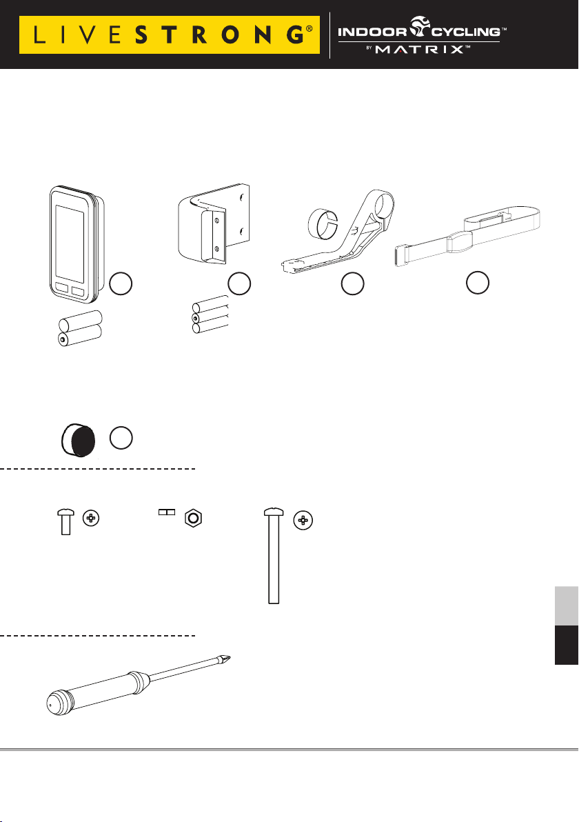
PARTLIST
2x 1x
2x 1x
1x
2x 1x
1x
2x 1x
1x
1x
2x 1x
1x
1x
1x
2x 1x
2x 1x
1x
2x 1x
2x 1x
1x
Computer console Wireless cadence
Art.no.: 020121
Art.no.: ST 020121
transmitter
Art.no.: 020123
Art.no.: ST 020123
1 2 3
AAA
AA
AA
Magnet
Art.no.: 020124
Art.no.: ST 020124
AAA
AAA
5
A
B C
Computer
mounting bracket
Art.no.: 020122
Art.no.: ST 020122
Textile heart
rate chest belt
Art.no.: 020125
Art.no.: ST 020125
4
optional
accessory
2x
M4 x 10
Version 1.1 2010 SBLS Copyright by Indoorcycling Group GmbH 2010 | www.indoorcycling.com ENG 9
1x 2x
M5
PZ 2
M5 x 50
ENG ESP
2x 1x
1x
PZ 2
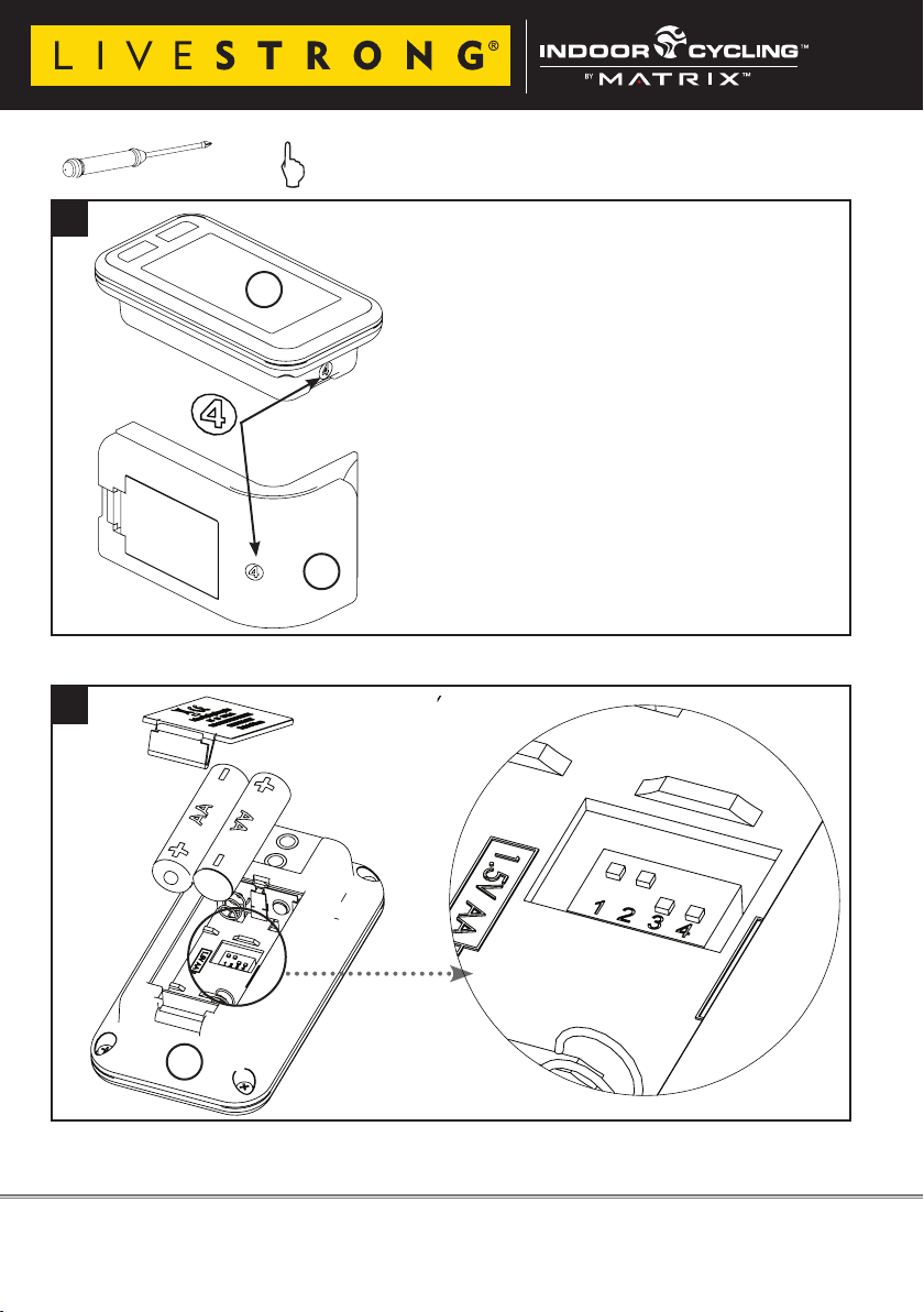
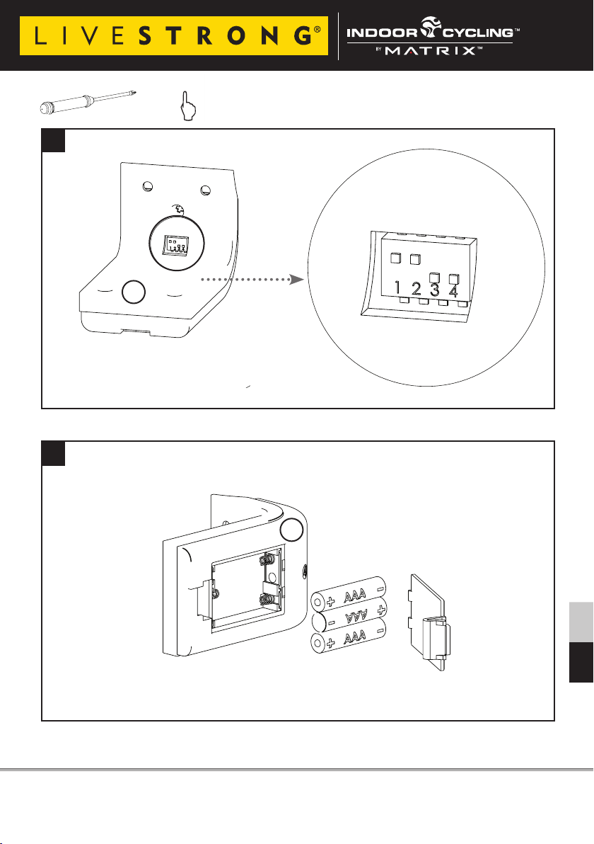
CHANNEL SETTING & BATTERIE INSTALLATION
hand tight
1
The channel transmitting the cadence signal
from the transmitter to the computer console is
pre set. A sticker on the housing indicates the
1
preset channel on computer & transmitter.
The channel can manually be changed. To
avoid cross reading please assure a clearance
of 52`` (1,3m) between components set on
identical channels or simply swap to another
default setting
channel.
To assure that the digital cadence signal is
synchronized, please assure that the channel
setting on the computer console corresponds
with the setting of the cadence transmitter on
the front fork.
2
Please view picture no. 2 and 3.
2
1
The use of rechargable Batteries may leads to male function of the computer and transmitter units due to a voltage lesser than 1,5V
Version 1.1 2010 SBLS Copyright by Indoorcycling Group GmbH 2010 | www.indoorcycling.com ENG 10
CHANNEL SETTING & BATTERIE INSTALLATION
2x 1x
1x
PZ 2
hand tight
3
2
4
2
The use of rechargable Batteries may leads to male function of the computer and transmitter units due to a voltage lesser than 1,5V
Version 1.1 2010 SBLS Copyright by Indoorcycling Group GmbH 2010 | www.indoorcycling.com ENG 11
ENG ESP
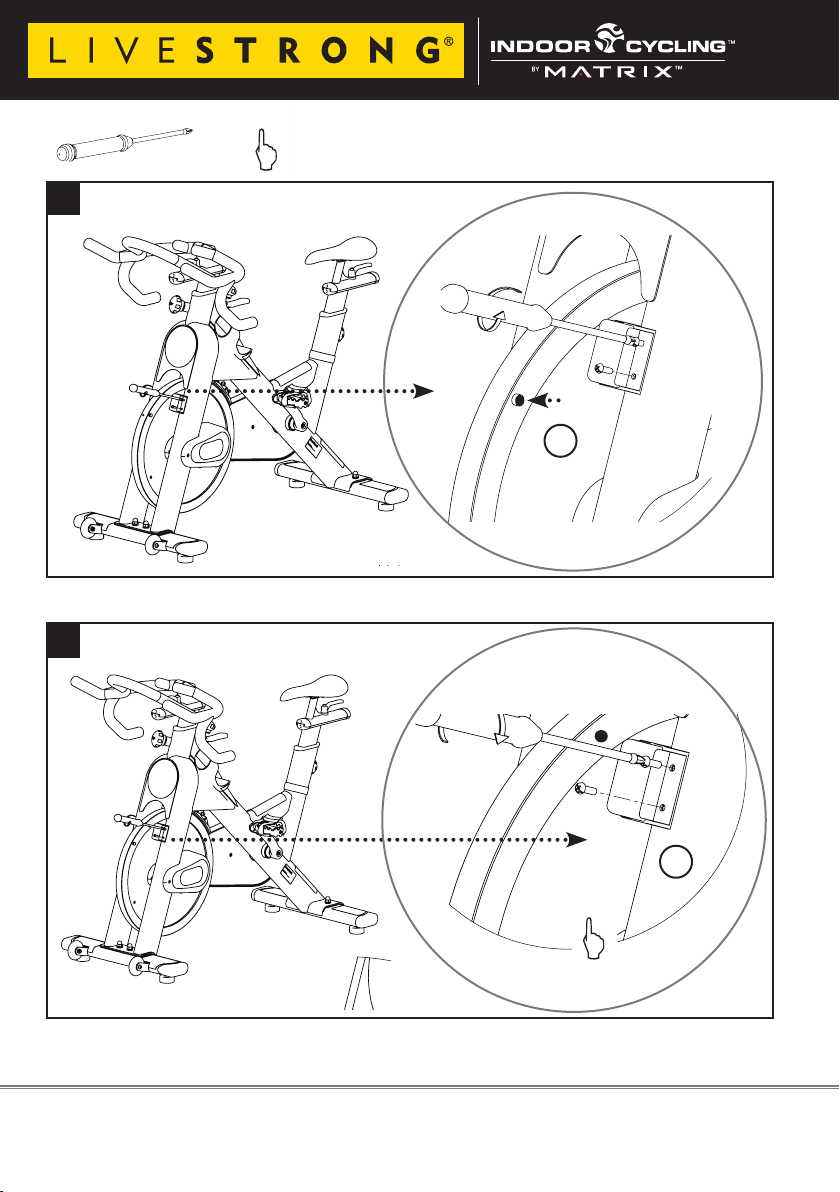
TRANSMITTER & COMPUTER ASSEMBLY
2x 1x
1x
PZ 2
hand tight
5
sensor
Magnet
5
Screws are made of plastic in order to avoid rust point. Do not overtighten and strip the head.
6
Magnet
sensor
2
Version 1.1 2010 SBLS Copyright by Indoorcycling Group GmbH 2010 | www.indoorcycling.com ENG 12
 Loading...