

LivaNova VNS Therapy 250 Physician's Manual
Physician’s Manual
For Healthcare Professionals
VNS Therapy®
Programming Software
Model 250 Version 8.1
Handheld Computer
June 2017
Worldwide Version
Caution: U.S. federal law restricts this device to
sale by or on the order of a physician.
Note: This manual contains information on the use of the LivaNova VNS Therapy Programming
Software, Model 250 Version 8.1. Physicians should refer to the VNS Therapy Pulse Generator
physician’s manuals for additional important prescribing and safety information. A copy of this VNS
Therapy manual is posted at www.livanova.com.
0344
2011
26-0008-1100/5 (Worldwide) — 1 of 92

Physician’s Manual — VNS Therapy Programming Software (8.1)
© Copyright 2012-2017 LivaNova, PLC, London, UK
All rights reserved.
LivaNova is a registered United States trademark of LivaNova, PLC. NCP, Demipulse, Demipulse
Duo, Perennia, VNS Therapy, AspireHC, PerenniaFLEX, PerenniaDURA and AspireSR are registered
trademarks of LivaNova USA, Inc. Pulse and Pulse Duo are trademarks of LivaNova USA, Inc.
Corresponding foreign trademarks may also be registered or pending.
2 of 92 — 26-0008-1100/5 (Worldwide)

Physician’s Manual — VNS Therapy Programming Software (8.1)
Table of Contents
1. BRIEF DEVICE DESCRIPTION . . . . . . . . . . . . . . . . . . . . . . . . . . . . . . . . . . . . . 9
1.1. General Description . . . . . . . . . . . . . . . . . . . . . . . . . . . . . . . . . . . . . . 9
1.2. Symbols . . . . . . . . . . . . . . . . . . . . . . . . . . . . . . . . . . . . . . . . . . . . . . . 9
1.3. Intended Use . . . . . . . . . . . . . . . . . . . . . . . . . . . . . . . . . . . . . . . . . . 10
1.4. System Requirements . . . . . . . . . . . . . . . . . . . . . . . . . . . . . . . . . . . 10
1.5. Conventions Used in this Manual . . . . . . . . . . . . . . . . . . . . . . . . . . 10
1.6. Communication Signals . . . . . . . . . . . . . . . . . . . . . . . . . . . . . . . . . . 11
2. H
OW TO GET STARTED . . . . . . . . . . . . . . . . . . . . . . . . . . . . . . . . . . . . . . . . 12
3. H
OW TO USE THE SOFTWARE . . . . . . . . . . . . . . . . . . . . . . . . . . . . . . . . . . 13
3.1. MAIN Menu . . . . . . . . . . . . . . . . . . . . . . . . . . . . . . . . . . . . . . . . . . 13
3.1.1. Interrogate Device overview . . . . . . . . . . . . . . . . . . . . . . . . 13
3.1.2. View Database overview . . . . . . . . . . . . . . . . . . . . . . . . . . . 13
3.1.3. View Last Parameters overview . . . . . . . . . . . . . . . . . . . . . . 13
3.1.4. User Preferences overview . . . . . . . . . . . . . . . . . . . . . . . . . 13
4. I
NTERROGATE DEVICE . . . . . . . . . . . . . . . . . . . . . . . . . . . . . . . . . . . . . . . . 14
4.1. How to Program New Parameter Settings . . . . . . . . . . . . . . . . . . . . 21
4.1.1. Partial Programming Due to Interrupted Programming
Operation . . . . . . . . . . . . . . . . . . . . . . . . . . . . . . . . . . . . . . . 23
4.1.2. Cross-programming (applicable to Model 100, 101, and
102 Pulse Generators ONLY) . . . . . . . . . . . . . . . . . . . . . . . 26
4.2. PARAMETER Screen Menu . . . . . . . . . . . . . . . . . . . . . . . . . . . . . . 27
4.2.1. Interrogate Device . . . . . . . . . . . . . . . . . . . . . . . . . . . . . . . . 28
4.2.2. Device Diagnostics . . . . . . . . . . . . . . . . . . . . . . . . . . . . . . . 28
4.2.2.1. Interrupted System and Generator Diagnostics . . . 31
4.2.2.2. Diagnostic test parameters . . . . . . . . . . . . . . . . . . . 34
4.2.2.3. System Diagnostics . . . . . . . . . . . . . . . . . . . . . . . . 39
4.2.2.4. Normal Mode Diagnostics . . . . . . . . . . . . . . . . . . . 40
4.2.2.5. Magnet Mode Diagnostics . . . . . . . . . . . . . . . . . . . 41
4.2.2.6. Generator Diagnostics . . . . . . . . . . . . . . . . . . . . . . 42
4.2.3. Program Patient Data screen . . . . . . . . . . . . . . . . . . . . . . . 44
4.2.4. Display Device History screen . . . . . . . . . . . . . . . . . . . . . . . 45
4.2.5. View Database screen . . . . . . . . . . . . . . . . . . . . . . . . . . . . . 46
4.2.6. Close Menu . . . . . . . . . . . . . . . . . . . . . . . . . . . . . . . . . . . . . 46
4.2.7. Main Menu . . . . . . . . . . . . . . . . . . . . . . . . . . . . . . . . . . . . . . 46
4.2.8. Handheld computer battery status . . . . . . . . . . . . . . . . . . . . 46
5. V
IEW DATABASE . . . . . . . . . . . . . . . . . . . . . . . . . . . . . . . . . . . . . . . . . . . . 47
5.1. Specify Search Limits . . . . . . . . . . . . . . . . . . . . . . . . . . . . . . . . . . . 47
5.1.1. Sort by Date, Patient ID, or Serial Number . . . . . . . . . . . . . 48
5.1.2. View All Records . . . . . . . . . . . . . . . . . . . . . . . . . . . . . . . . . 48
5.1.3. Earliest Date/Latest Date . . . . . . . . . . . . . . . . . . . . . . . . . . . 49
5.1.4. Patient ID . . . . . . . . . . . . . . . . . . . . . . . . . . . . . . . . . . . . . . . 49
5.1.5. Serial Number . . . . . . . . . . . . . . . . . . . . . . . . . . . . . . . . . . . 49
5.2. View the Records . . . . . . . . . . . . . . . . . . . . . . . . . . . . . . . . . . . . . . . 49
5.2.1. View Parameter History . . . . . . . . . . . . . . . . . . . . . . . . . . . . 49
5.2.2. View Diagnostic History . . . . . . . . . . . . . . . . . . . . . . . . . . . 50
5.2.3. View Magnet History . . . . . . . . . . . . . . . . . . . . . . . . . . . . . . 51
26-0008-1100/5 (Worldwide) — 3 of 92

Physician’s Manual — VNS Therapy Programming Software (8.1)
6. VIEW LAST PARAMETERS . . . . . . . . . . . . . . . . . . . . . . . . . . . . . . . . . . . . . 53
7. U
SER PREFERENCES SCREEN. . . . . . . . . . . . . . . . . . . . . . . . . . . . . . . . . . . . 54
7.1. Set Timeout . . . . . . . . . . . . . . . . . . . . . . . . . . . . . . . . . . . . . . . . . . . 54
7.2. Set Maximum Number of Records to View . . . . . . . . . . . . . . . . . . 55
7.3. Set the Font Size for Database Displays . . . . . . . . . . . . . . . . . . . . . 55
7.4. Set Time and Date . . . . . . . . . . . . . . . . . . . . . . . . . . . . . . . . . . . . . . 55
7.5. Backup to FlashCard . . . . . . . . . . . . . . . . . . . . . . . . . . . . . . . . . . . . 56
7.6. Restore from FlashCard . . . . . . . . . . . . . . . . . . . . . . . . . . . . . . . . . . 56
7.7. Export Database to Text File . . . . . . . . . . . . . . . . . . . . . . . . . . . . . . 56
7.8. Language Selection . . . . . . . . . . . . . . . . . . . . . . . . . . . . . . . . . . . . . 56
7.9. Handheld Computer Battery Status . . . . . . . . . . . . . . . . . . . . . . . . . 57
8. M
AINTENANCE, HANDLING, AND STORAGE . . . . . . . . . . . . . . . . . . . . . . . . 58
9. P
RECAUTIONS . . . . . . . . . . . . . . . . . . . . . . . . . . . . . . . . . . . . . . . . . . . . . . 59
10. T
ROUBLESHOOTING . . . . . . . . . . . . . . . . . . . . . . . . . . . . . . . . . . . . . . . . . . . 61
10.1. General Recommendations . . . . . . . . . . . . . . . . . . . . . . . . . . . . . . . 61
10.1.1. Non-responsive Handheld Computer . . . . . . . . . . . . . . . . . . 61
10.2. Hardware Issues . . . . . . . . . . . . . . . . . . . . . . . . . . . . . . . . . . . . . . . . 62
10.2.1. Restore and reinstall software . . . . . . . . . . . . . . . . . . . . . . . 62
10.2.2. Handheld screen alignment . . . . . . . . . . . . . . . . . . . . . . . . . 62
10.2.2.1.Screen alignment for the Dell Axim X5 handheld
computer . . . . . . . . . . . . . . . . . . . . . . . . . . . . . . . . 62
10.2.2.2.Screen alignment for the Dell Axim X50 handheld
computer . . . . . . . . . . . . . . . . . . . . . . . . . . . . . . . . 63
10.2.3. Other hardware issues . . . . . . . . . . . . . . . . . . . . . . . . . . . . . 64
10.3. Troubleshooting in the OR . . . . . . . . . . . . . . . . . . . . . . . . . . . . . . . 64
10.3.1. Communication problems in OR . . . . . . . . . . . . . . . . . . . . . 64
10.3.2. High Lead impedance on System Diagnostics in OR –
initial implant . . . . . . . . . . . . . . . . . . . . . . . . . . . . . . . . . . . . 68
10.3.3. High Lead impedance on System Diagnostics in OR –
Pulse Generator replacement . . . . . . . . . . . . . . . . . . . . . . . . 69
10.3.4. Low Lead impedance on System Diagnostics in OR –
initial implant . . . . . . . . . . . . . . . . . . . . . . . . . . . . . . . . . . . . 72
10.3.5. Low Lead impedance on System Diagnostics in OR –
Pulse Generator replacement . . . . . . . . . . . . . . . . . . . . . . . . 74
10.3.6. Low Battery/End of Service indications prior to surgery,
outside of the sterile field – initial implant or Pulse Generator
replacement . . . . . . . . . . . . . . . . . . . . . . . . . . . . . . . . . . . . . 75
10.3.7. Low Battery/End of Service indications during surgery,
inside the sterile field – initial implant or Pulse Generator
replacement . . . . . . . . . . . . . . . . . . . . . . . . . . . . . . . . . . . . . 77
10.4. Troubleshooting at Follow-up Visits . . . . . . . . . . . . . . . . . . . . . . . . 78
10.4.1. Communication problems at follow-up visits . . . . . . . . . . . . 78
10.4.2. High Lead Impedance on a Diagnostic Test at follow-up
visit for Models 100, 101, and 102 Pulse Generators . . . . . 79
10.4.3. High Lead Impedance, Low Lead Impedance, or Low
Output Current on a Diagnostic Test at follow-up visit
for Model 103, 104, and 105 Pulse Generators . . . . . . . . . . 83
10.4.4. Pulse Generator disabled due to Vbat < EOS found
at first interrogation after implantation or other
surgical procedure . . . . . . . . . . . . . . . . . . . . . . . . . . . . . . . . 85
4 of 92 — 26-0008-1100/5 (Worldwide)

Physician’s Manual — VNS Therapy Programming Software (8.1)
10.4.5. Sudden decrease in estimated device longevity (% battery
power remaining) . . . . . . . . . . . . . . . . . . . . . . . . . . . . . . . . . 86
11. G
LOSSARY. . . . . . . . . . . . . . . . . . . . . . . . . . . . . . . . . . . . . . . . . . . . . . . . . . 87
12. L
IST OF APPROVED COMPUTERS . . . . . . . . . . . . . . . . . . . . . . . . . . . . . . . . 91
13. P
RODUCT INFORMATION AND SUPPORT . . . . . . . . . . . . . . . . . . . . . . . . . . . 92
List of Tables
TABLE 1PULSE GENERATOR BATTERY LEVEL INDICATIONS AND
R
ECOMMENDATIONS . . . . . . . . . . . . . . . . . . . . . . . . . . . . . . . . . . 19
T
ABLE 2PROGRAMMABLE PARAMETERS FOR THE PULSE GENERATOR . . 21
T
ABLE 3CROSS-PROGRAMMING EXAMPLE . . . . . . . . . . . . . . . . . . . . . . . . 27
T
ABLE 4DEVICE DIAGNOSTIC SCREEN STATUS READINGS FOR
C
OMMUNICATION . . . . . . . . . . . . . . . . . . . . . . . . . . . . . . . . . . . . 34
T
ABLE 5DEVICE DIAGNOSTIC SCREEN STATUS READINGS FOR OUTPUT
S
TATUS . . . . . . . . . . . . . . . . . . . . . . . . . . . . . . . . . . . . . . . . . . . . 35
T
ABLE 6DEVICE DIAGNOSTIC SCREEN STATUS READINGS FOR OUTPUT
C
URRENT FOR MODELS 100, 101, AND 102 . . . . . . . . . . . . . . . . 36
T
ABLE 7DEVICE DIAGNOSTIC SCREEN STATUS READINGS FOR LEAD
I
MPEDANCE . . . . . . . . . . . . . . . . . . . . . . . . . . . . . . . . . . . . . . . . . 36
T
ABLE 8DC-DC CONVERTER CODES AND LEAD IMPEDANCE (MODEL
100, SN ³10,000) . . . . . . . . . . . . . . . . . . . . . . . . . . . . . . . . . . . . . 37
T
ABLE 9DC-DC CONVERTER CODES AND LEAD IMPEDANCE
(M
ODEL 101) . . . . . . . . . . . . . . . . . . . . . . . . . . . . . . . . . . . . . . . . 37
T
ABLE 10 DC-DC CONVERTER CODES AND LEAD IMPEDANCE
(M
ODEL 102) . . . . . . . . . . . . . . . . . . . . . . . . . . . . . . . . . . . . . . . . 38
T
ABLE 11 MINIMUM NORMAL MODE AND MAGNET MODE DIAGNOSTIC
S
ETTINGS (MODELS 100, 101, AND 102) . . . . . . . . . . . . . . . . . . . 42
26-0008-1100/5 (Worldwide) — 5 of 92

Physician’s Manual — VNS Therapy Programming Software (8.1)
List of Figures
FIGURE 1 MAIN MENU . . . . . . . . . . . . . . . . . . . . . . . . . . . . . . . . . . . . . . . . 12
F
IGURE 2 START INTERROGATION SCREEN . . . . . . . . . . . . . . . . . . . . . 14
F
IGURE 3 PARAMETER SCREEN . . . . . . . . . . . . . . . . . . . . . . . . . . . . . . . . 15
F
IGURE 4 TIMEOUT WARNING SCREEN . . . . . . . . . . . . . . . . . . . . . . . . . 16
F
IGURE 5 PARAMETER SCREEN WITH ACTIVE BATTERY STATUS
INDICATOR . . . . . . . . . . . . . . . . . . . . . . . . . . . . . . . . . . . . . . . . 17
F
IGURE 6 BATTERY STATUS INDICATOR - NEAR EOS WARNING
S
CREEN . . . . . . . . . . . . . . . . . . . . . . . . . . . . . . . . . . . . . . . . . . . . 17
F
IGURE 7 BATTERY STATUS INDICATOR - IFI WARNING
S
CREEN . . . . . . . . . . . . . . . . . . . . . . . . . . . . . . . . . . . . . . . . . . . . 18
F
IGURE 8 BATTERY STATUS INDICATOR - N EOS WARNING
S
CREEN . . . . . . . . . . . . . . . . . . . . . . . . . . . . . . . . . . . . . . . . . . . . 18
F
IGURE 9 PULSE DISABLED AND BATTERY STATUS INDICATOR
- EOS WARNING S
F
IGURE 10 PARAMETER SETTINGS POP-UP MENU . . . . . . . . . . . . . . . . 22
CREEN . . . . . . . . . . . . . . . . . . . . . . . . . . . . . 19
F
IGURE 11 OUTPUT WARNING . . . . . . . . . . . . . . . . . . . . . . . . . . . . . . . . 22
F
IGURE 12 START PROGRAMMING SCREEN . . . . . . . . . . . . . . . . . . . . . . 23
F
IGURE 13 PROGRAMMING FAILED WARNING SCREEN . . . . . . . . . . . 24
F
IGURE 14 CHANGED SETTINGS PROGRAMMING WARNING
S
CREEN . . . . . . . . . . . . . . . . . . . . . . . . . . . . . . . . . . . . . . . . . . . . 25
F
IGURE 15 PROGRAMMING FAILED WARNING SCREEN . . . . . . . . . . . 26
F
IGURE 16 PARAMETER SCREEN MENU . . . . . . . . . . . . . . . . . . . . . . . . . . 28
F
IGURE 17 DEVICE DIAGNOSTICS MENU . . . . . . . . . . . . . . . . . . . . . . . . 29
F
IGURE 18 DEVICE DIAGNOSTICS SUB-MENU . . . . . . . . . . . . . . . . . . . . 30
F
IGURE 19 DIAGNOSTIC - SINGLE FAILURE WARNING SCREEN . . . . 32
F
IGURE 20 DIAGNOSTIC - MULTIPLE FAILURE WARNING SCREEN . 32
F
IGURE 21 CHANGED SETTINGS - INTERRUPTED DIAGNOSTIC
WARNING S
F
IGURE 22 PARAMETER SCREEN WITH UNKNOWN SETTINGS . . . . . . 33
F
IGURE 23 SYSTEM DIAGNOSTICS SCREEN . . . . . . . . . . . . . . . . . . . . . . 40
F
IGURE 24 NORMAL MODE DIAGNOSTICS SCREEN . . . . . . . . . . . . . . . 41
F
IGURE 25 MAGNET MODE DIAGNOSTICS SCREEN . . . . . . . . . . . . . . . 42
F
IGURE 26 GENERATOR DIAGNOSTICS SCREEN . . . . . . . . . . . . . . . . . . 43
F
IGURE 27 PROGRAM PATIENT DATA SCREEN . . . . . . . . . . . . . . . . . . . 44
CREEN . . . . . . . . . . . . . . . . . . . . . . . . . . . . . . . . . . 33
F
IGURE 28 DEVICE HISTORY SCREEN . . . . . . . . . . . . . . . . . . . . . . . . . . . 45
F
IGURE 29 VIEW DATABASE SCREEN . . . . . . . . . . . . . . . . . . . . . . . . . . . . 48
F
IGURE 30 VIEW PARAMETER HISTORY SCREEN . . . . . . . . . . . . . . . . . 50
F
IGURE 31 VIEW DIAGNOSTIC HISTORY SCREEN . . . . . . . . . . . . . . . . . 51
6 of 92 — 26-0008-1100/5 (Worldwide)

Physician’s Manual — VNS Therapy Programming Software (8.1)
FIGURE 32 VIEW MAGNET HISTORY SCREEN . . . . . . . . . . . . . . . . . . . . 52
F
IGURE 33 VIEW LAST PARAMETERS SCREEN . . . . . . . . . . . . . . . . . . . 53
F
IGURE 34 USER PREFERENCES SCREEN . . . . . . . . . . . . . . . . . . . . . . . . . 54
F
IGURE 35 LANGUAGE SELECTION SCREEN . . . . . . . . . . . . . . . . . . . . . 57
F
IGURE 36 CORRECT FLASHCARD ORIENTATION . . . . . . . . . . . . . . . . . . . . . 60
F
IGURE 37 DELL AXIM X5 HANDHELD COMPUTER . . . . . . . . . . . . . . . . . . . 63
F
IGURE 38 DELL AXIM X50 HANDHELD COMPUTER . . . . . . . . . . . . . . . . . . 64
F
IGURE 39 COMMUNICATION PROBLEMS IN THE OR AND AT FOLLOW-UP
V
ISITS . . . . . . . . . . . . . . . . . . . . . . . . . . . . . . . . . . . . . . . . . . . . . 67
F
IGURE 40 HIGH LEAD IMPEDANCE ON SYSTEM DIAGNOSTIC TEST IN OR -
I
NITIAL IMPLANT OR GENERATOR REPLACEMENT . . . . . . . . . . . 71
F
IGURE 41 LOW LEAD IMPEDANCE ON SYSTEM DIAGNOSTICS IN OR -
I
NITIAL IMPLANT . . . . . . . . . . . . . . . . . . . . . . . . . . . . . . . . . . . . 73
F
IGURE 42 LOW LEAD IMPEDANCE ON SYSTEM DIAGNOSTICS IN OR -
P
ULSE GENERATOR REPLACEMENT . . . . . . . . . . . . . . . . . . . . . . . 74
F
IGURE 43 LOW BATTERY/END OF SERVICE INDICATIONS PRIOR TO
S
URGERY, OUTSIDE OF THE STERILE FIELD - INITIAL
I
MPLANT OR PULSE GENERATOR REPLACEMENT . . . . . . . . . . . . 76
F
IGURE 44 HIGH LEAD IMPEDANCE ON A DIAGNOSTIC TEST AT
F
OLLOW-UP VISIT FOR MODELS 100, 101, AND 102 PULSE
G
ENERATORS . . . . . . . . . . . . . . . . . . . . . . . . . . . . . . . . . . . . . . . . 82
F
IGURE 45 HIGH LEAD IMPEDANCE, LOW LEAD IMPEDANCE, OR
L
OW OUTPUT CURRENT ON AN INTERROGATION OR
D
IAGNOSTIC TEST AT FOLLOW-UP VISIT FOR MODELS
103, 104,
AND 105 PULSE GENERATORS . . . . . . . . . . . . . . . . . . . 84
26-0008-1100/5 (Worldwide) — 7 of 92

Physician’s Manual — VNS Therapy Programming Software (8.1)
8 of 92 — 26-0008-1100/5 (Worldwide)
Physician’s Manual — VNS Therapy Programming Software (8.1)
1. BRIEF DEVICE DESCRIPTION ___________
1.1. General Description
The LivaNova® VNS Therapy® Programming Software, Model 250
Version 8.1, enables you to interrogate and program LivaNova’ Pulse
Generator using the Programming Wand.
Software capabilities include:
Use of the software with the Programming Wand to interrogate and
program a Pulse Generator’s parameters and assess Pulse Generator
function.
Use of the software without the Programming Wand to display the
operating histories of all the Pulse Generators interrogated with your
handheld computer.
Use of screen displays that provide prompts and messages to aid in
interrogating and programming.
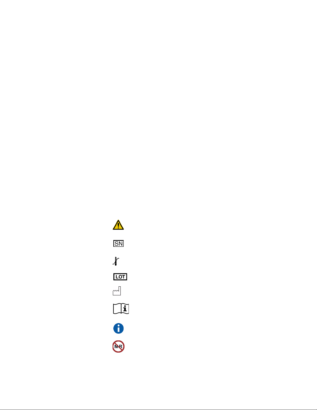
1.2. Symbols
Symbols and definitions used for the VNS Therapy System include the
following:
Notice for reader to pay special attention to details that
follow
Serial Number
Storage
Batch Code
Date of Manufacture
Information
Sidebar Note (cross-references and other useful
information)
MRI Unsafe
26-0008-1100/5 (Worldwide) — 9 of 92
Physician’s Manual — VNS Therapy Programming Software (8.1)
Humidity limitations—Indicates the range of humidity to
which the medical device can be safely exposed
1.3. Intended Use
The Model 250 VNS Therapy Programming Software is intended for use
only with the LivaNova Pulse Generators and Programming Wand and is
subject to the same indications for use.
1.4. System Requirements
The computer must have the following minimum specifications:
Microsoft
Pocket-PC (2002, 2003 Operating System) or Windows
Mobile (2003 2nd Edition)
At least 16 MB of memory
Compact FlashCard
Serial communication capability
The communication system of the VNS Therapy Programming Software
Model 250 Version 8.1 is designed to minimize the possibility of
misprogramming or “phantom” programming. Phantom programming is
the inadvertent programming via environmental sources of
electromagnetic interference.
For Models 100, 101, and 102 Pulse Generators, each parameter is
programmed and verified individually during a programming event. For
the Models 103, 104, and 105 Pulse Generators the parameters are
programmed and verified as a group during a programming event.
1.5. Conventions Used in this Manual
Caution: LivaNova
recommends that the
software be loaded on a
dedicated computer
used only to program
the Pulse Generator.
Note: See “List of
Approved Computers”
on page 91 for a list of
computers that have
been qualified for use
with the VNS Therapy
Programming Software
Model 250 Version 8.1.
Note: See the
physician’s manual for
the VNS Therapy Pulse
Generators for a
complete description of
the Pulse Generator, its
indications for use, and
its operation.
The following conventions are used throughout this manual:
The VNS Therapy Programming Software Model 250 Version 8.1
operates in a Windows environment with drop-down menus. You will
use a stylus to navigate through a Windows environment on the
handheld computer. The stylus resembles a small pen and is kept with
handheld computer.
Screen titles appear in all capital letters. The names of selectable
buttons (or fields) and drop-down menus appear in bold typeface. Each
of these buttons or fields represents an operation, parameter, or
parameter value.
10 of 92 — 26-0008-1100/5 (Worldwide)
Note: See the
physician’s manual for
the Programming Wand
for a description of the
Programming Wand.

Physician’s Manual — VNS Therapy Programming Software (8.1)
To select a button or field, tap it with the stylus.
Some information can be entered with a “soft” or “on-screen”
keyboard (an example of the soft keyboard is shown at the bottom of
Figure 27 on page 44). To maximize (enable) or minimize (disable) the
soft keyboard, tap the keyboard icon at the lower right-hand corner of
the screen. You can type letters or numbers by tapping them with the
stylus.
When a selection requires communication with the Pulse Generator, a
message will appear prompting you to hold the Programming Wand
over the Pulse Generator.
When a button is selected, a border will appear around the button (as
on the Interrogate Device button in Figure 1 on page 12).
To return to a previous screen, tap Menu or Exit.
A list of symbols is found in the front of this manual.
A glossary is found in the back of this manual.
The words ON and OFF appear in all capital letters only when they
refer to VNS stimulation.
References to Model 102 include both Models 102 and 102R.
For more information, see “Troubleshooting ” on page 61.
1.6. Communication Signals
Four rapid, ascending musical tones and a screen message signal the
successful completion of an interrogation or programming operation.
Four rapid, descending musical tones and a screen message signal a
warning or a failed operation.
The DATA/RCVD indicator on the Programming Wand lights up during a
successful programming operation or interrogation.
Caution: If the Procedure Failed message appears on the screen,
check both the connection between the handheld computer and the
Programming Wand and the positioning of the Programming Wand in
relation to the Pulse Generator (see the physician’s manual for the
Programming Wand). If you continue to have communication
problems, change the battery in the Programming Wand.
Caution: The DATA/RCVD indicator on the Programming Wand may
also light up or flicker in the presence of electromagnetic interference
(EMI) or noise. Information on how to detect EMI is provided in the
physician’s manual for the Programming Wand, sections entitled
Understanding the Indicator Lights and Troubleshooting. If the
presence of EMI or noise is suspected, you must verify that the
programming or interrogation occurred successfully by reviewing the
PARAMETER Screen shown in Figure 3 on page 15.
26-0008-1100/5 (Worldwide) — 11 of 92
Physician’s Manual — VNS Therapy Programming Software (8.1)
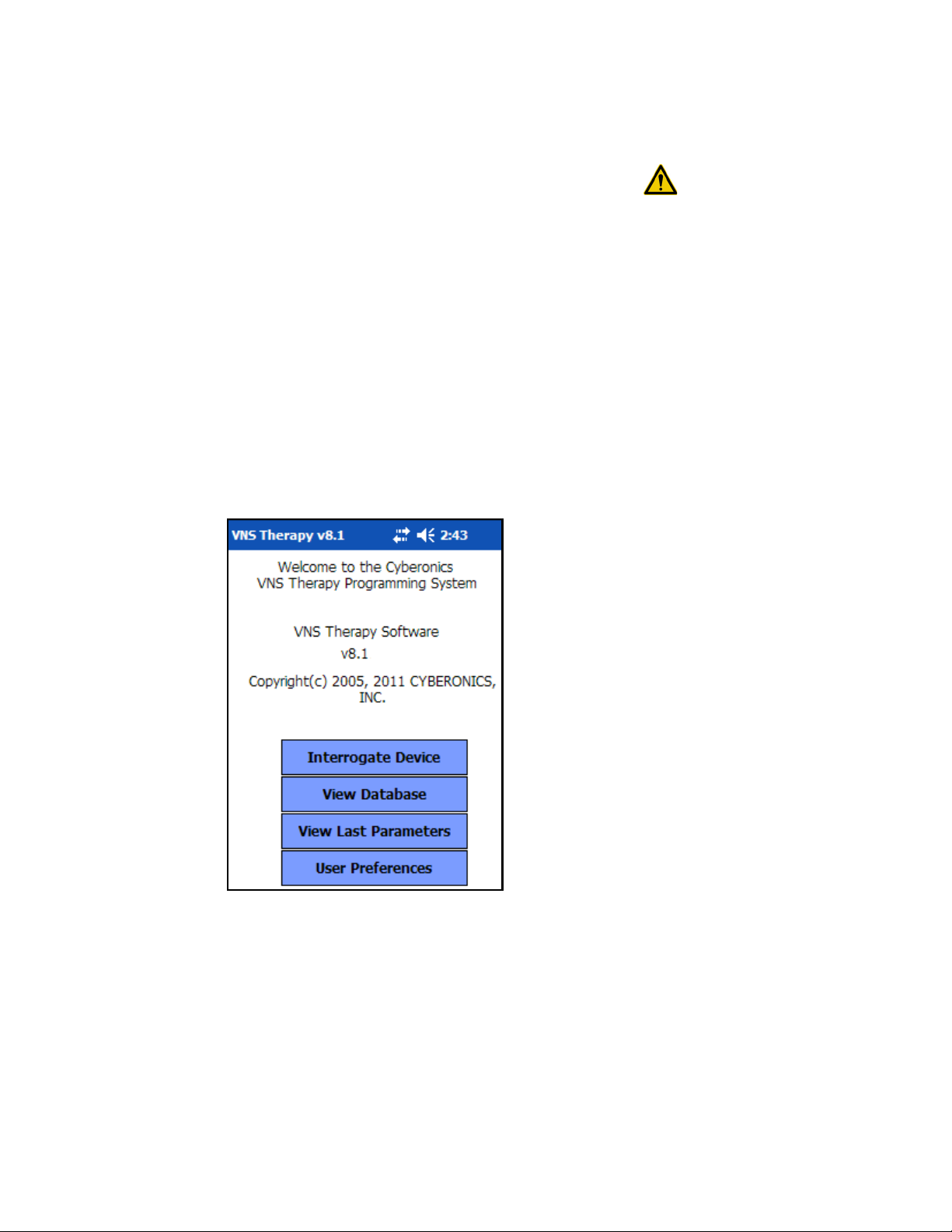
2. HOW TO GET STARTED _______________
The VNS Therapy Programming Software Model 250 Version 8.1 has
been pre-installed on the handheld computer. Before proceeding to the
next section, be sure you have arrived at the MAIN Menu as shown in
Figure 1. If for any reason the software must be reinstalled, directions for
doing so are provided in the Troubleshooting section of this manual.
1. Turn on the handheld computer by pressing the on-off button. The
handheld computer will display the same screen it was displaying
when it was last turned off (unless it was reset since the last use).
2. If the computer doesn’t display the MAIN Menu, select Exit or Menu
until the MAIN Menu is displayed.
3. If you haven’t been able to access the MAIN Menu after following
Steps 1 and 2 above, see “Precautions ” on page 59 and
“Troubleshooting ” on page 61 before proceeding.
Figure 1. MAIN Menu
Caution: When in use,
LivaNova recommends
the handheld computer
to be operated on
battery power only
(unplugged from AC
power). Having the
handheld computer
plugged into AC power
during use may
contribute to
communication
difficulties. When not in
use, the handheld
computer should be
plugged into AC power
to maintain charge.
12 of 92 — 26-0008-1100/5 (Worldwide)

Physician’s Manual — VNS Therapy Programming Software (8.1)
3. HOW TO USE THE SOFTWARE __________
It is LivaNova’s intent to make the software as intuitive and “user friendly”
as possible. Messages and prompts will guide you through this software.
There are four menus in this software. The first is the MAIN Menu.
3.1. MAIN Menu
The following sections provide an overview of each of the MAIN Menu’s
four primary functions, as shown in Figure 1.
3.1.1. Interrogate Device overview
Note: See “Interrogate
Device” on page 14 for
more information.
Note: See “View
Database” on page 47
for more information.
Note: See “View Last
Parameters” on page 53
for more information.
Note: See “User
Preferences Screen ” on
page 54 for more
information.
The first option, Interrogate Device, is used to establish communication
with the implantable device (Pulse Generator). The other three options
work with data stored on the handheld computer itself and require no link
to the device via the Programming Wand.
3.1.2. View Database overview
View Database is used to view information from all Pulse Generator
interrogations and programming events performed by your handheld
computer and the Programming Software.
3.1.3. View Last Parameters overview
View Last Parameters is used to view the most recent parameters selected
for a specific patient or Pulse Generator.
3.1.4. User Preferences overview
User Preferences allows you to select values for five user settings:
The number of minutes that the computer may be idle before a new
interrogation becomes necessary (applicable for Models 100C, 101,
and 102 only).
The maximum number of records viewable at a time
The size of type font for the diagnostics screens
The current time and date
Language selection, when available
26-0008-1100/5 (Worldwide) — 13 of 92
Physician’s Manual — VNS Therapy Programming Software (8.1)
4. INTERROGATE DEVICE________________
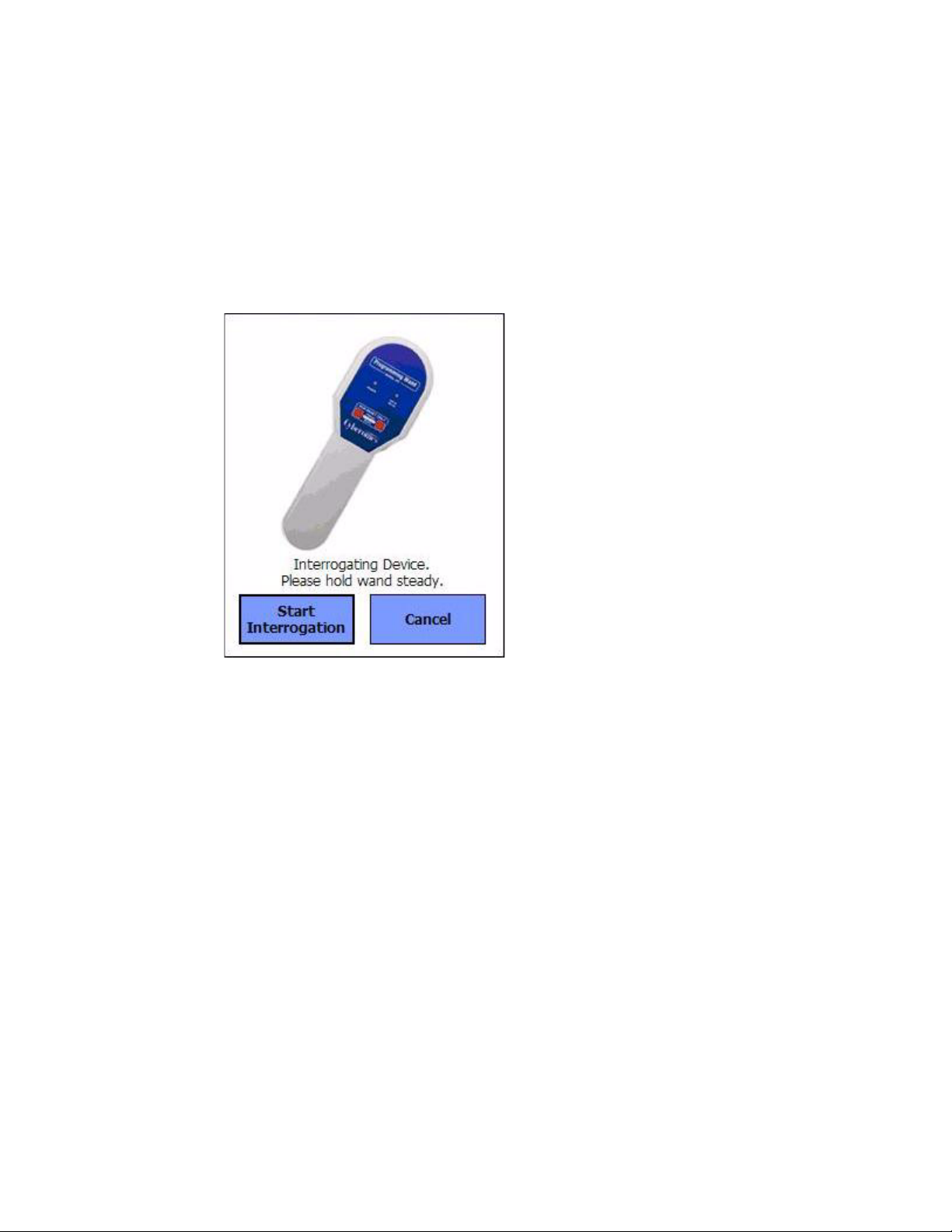
To retrieve information from the Pulse Generator or to program the Pulse Generator, you must first select the Interrogate Device button from the MAIN Menu. The START INTERROGATION Screen will be displayed (see Figure 2).
Figure 2. START INTERROGATION Screen
To interrogate the Pulse Generator, place the Programming Wand over the
Pulse Generator and tap Start Interrogation. Tap Cancel to return to the
previous screen.
Upon completion of a successful interrogation, the Programming Software
automatically displays the PARAMETER screen (see Figure 3 on page 15)
unless an error condition (i.e., Generator End of Service or High Lead
Impedance) is detected with the Pulse Generator. If an error condition is
detected with the Pulse Generator, the associated warning message is
displayed and must be acknowledged by the user before proceeding to the
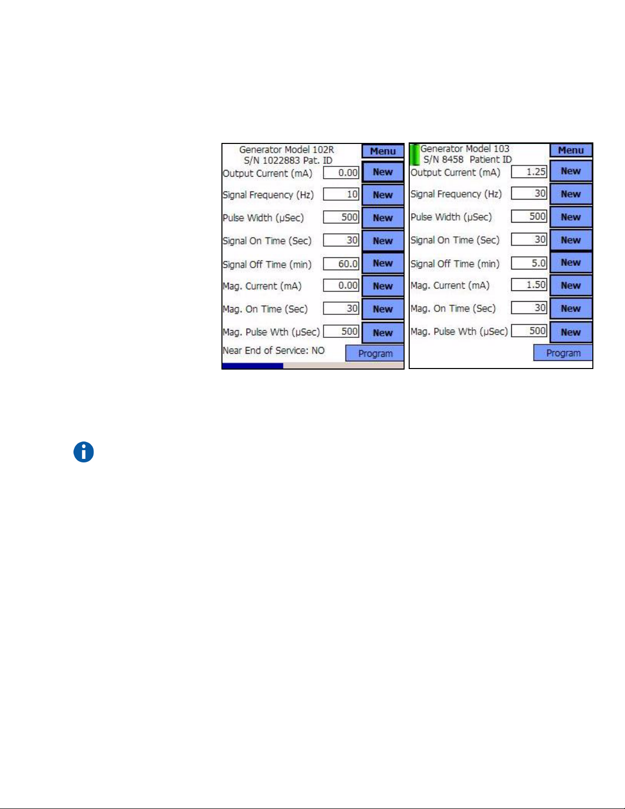
PARAMETER screen. The PARAMETER screen displays the operating
parameters of the Pulse Generator with their current settings.
There is one line for each of the eight parameters. Each line contains three
types of information:
1. The name of the parameter and the units used to express its values
2. The present setting for that particular parameter (***** is shown for
any unknown or out of range parameter values)
14 of 92 — 26-0008-1100/5 (Worldwide)
Physician’s Manual — VNS Therapy Programming Software (8.1)
Models 100, 101, 102 Models 103, 104, 105
3. The New button, when tapped, displays the range of possible settings
for that parameter
Figure 3. PARAMETER Screen
Note: The inactivity
timeout function is not
used in Models 103,
104, and 105.
↑ Inactivity Timeout Indicator (Progress Bar)
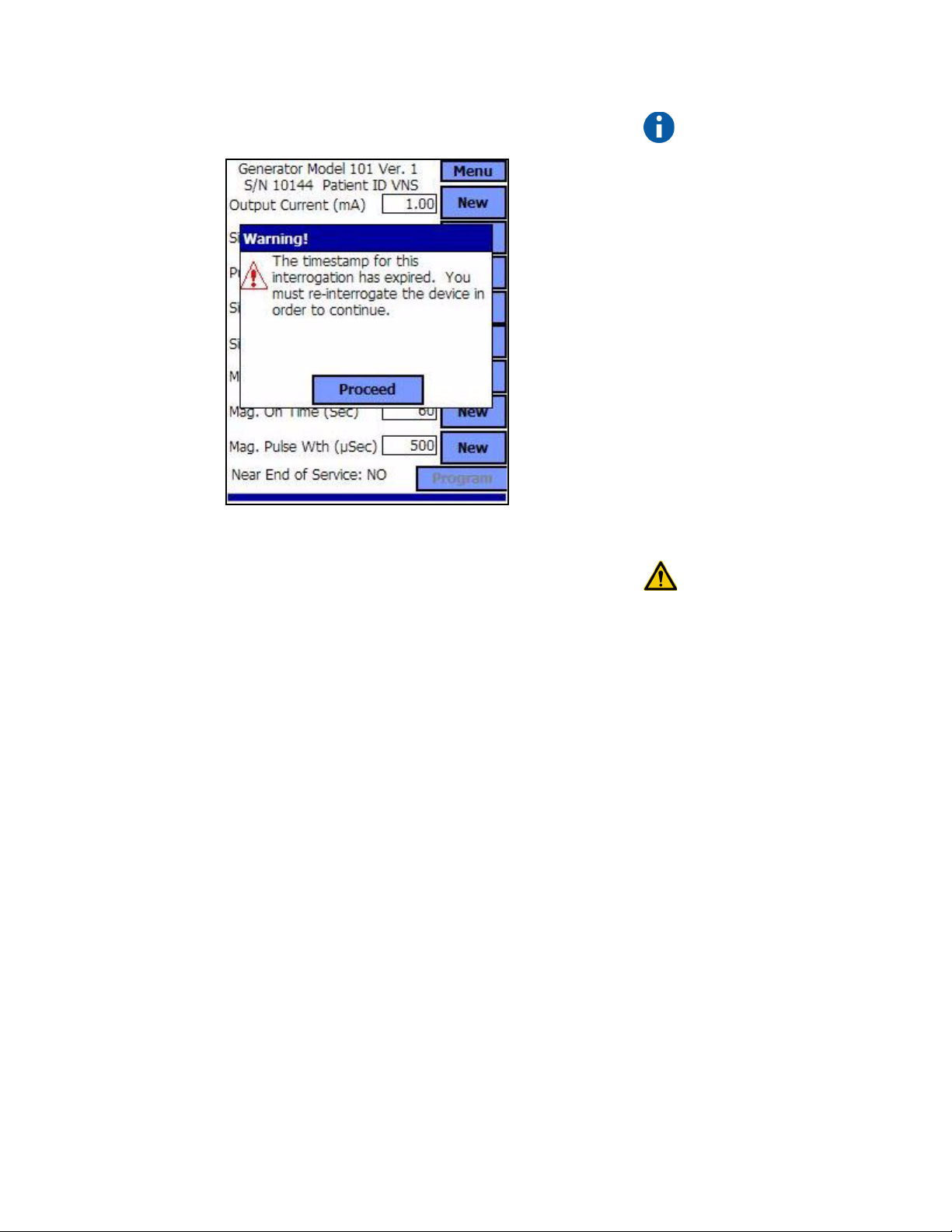
For the Models 100, 101, 102 Pulse Generators, the progress bar across the
bottom of the screen is an “inactivity timeout” indicator. When the bar
reaches the right margin, the most recent interrogation will have expired
and the warning shown in Figure 4 on page 16 will be displayed. Also, it
will be necessary to reinterrogate the Pulse Generator before
programming. The inactivity timeout period can be adjusted on the USER
PREFERENCES Screen. See See “User Preferences Screen ” on page 54.
26-0008-1100/5 (Worldwide) — 15 of 92
Physician’s Manual — VNS Therapy Programming Software (8.1)
Figure 4. TIMEOUT WARNING Screen
Note that the timeout bar has advanced to the right margin.
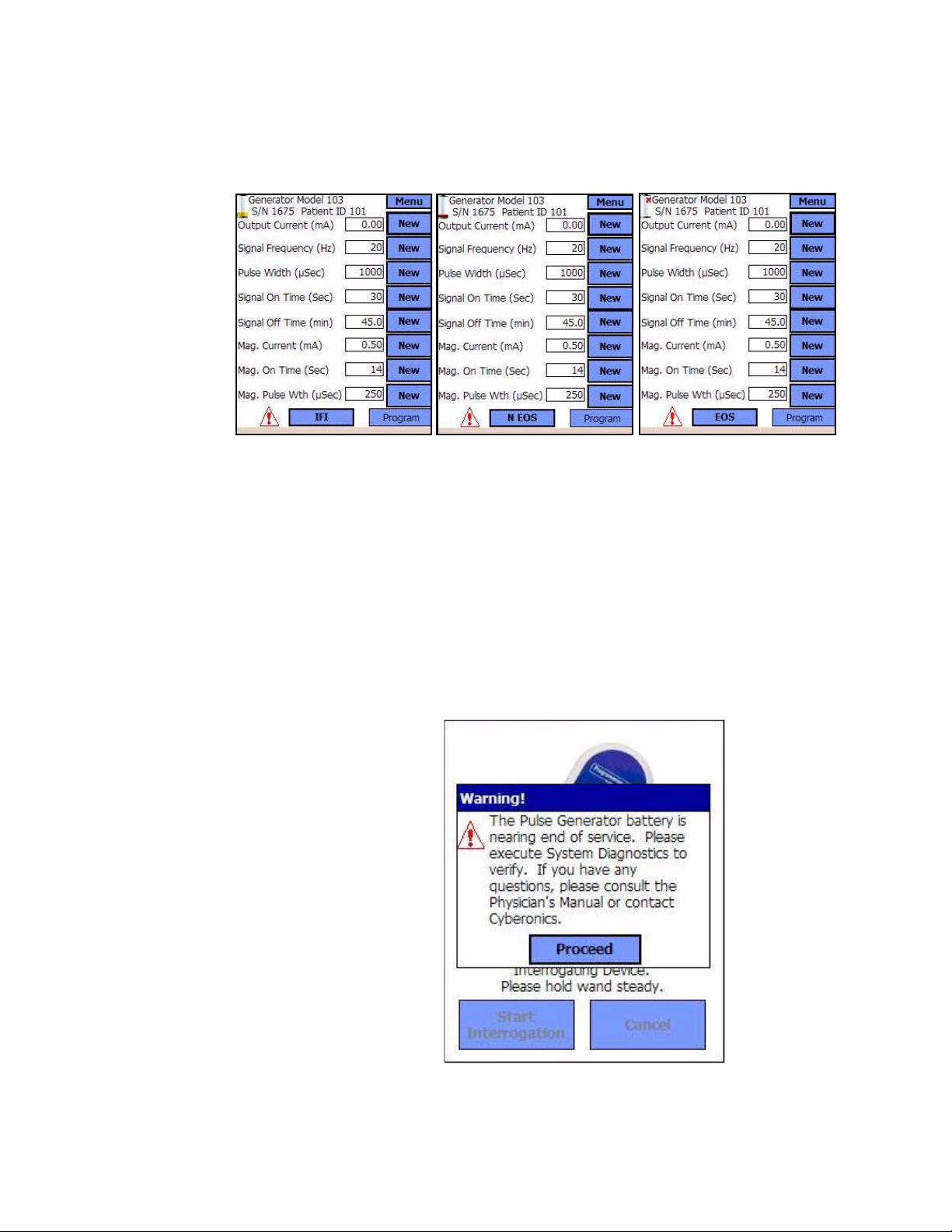
In addition to the eight programmable parameters, the PARAMETER
screen will also indicate battery status for the Pulse Generator. The
Programming Software has one battery status indicator, Near End of
Service (Near EOS), for Models 100, 101, and 102 Pulse Generators. The
Programming Software has three indicators, Intensified Follow-up
Indicator (IFI), Near End of Service (N EOS), and End of Service (EOS),
for Models 103, 104, and 105 Pulse Generators. On the PARAMETER
screen, the Near EOS status for Models 100, 101, and 102 Pulse
Generators is displayed on the lower portion of the screen (see Figure 3 on
page 15). For Model 103, 104, and 105 Pulse Generators, the remaining
generator battery power is indicated by the battery icon located in the top
left portion of the PARAMETER screen (see Figure 3 on page 15). The
battery icon is shaded and colored to indicate various levels of remaining
generator battery power. As the battery level decreases and the Pulse
Generator enter states of IFI = Yes, N EOS = Yes or EOS = Yes, an
additional indicator is displayed at the bottom of the PARAMETER screen
(see Figure 5 on page 17).
Note: For more
information on the
timeout function, see
“User Preferences
Screen ” on page 54.
Caution: LivaNova
recommends that you
reinterrogate the Pulse
Generator after each
programming event to
verify that the
programming occurred
as planned.
16 of 92 — 26-0008-1100/5 (Worldwide)
Physician’s Manual — VNS Therapy Programming Software (8.1)
Figure 5. PARAMETER Screen with ACTIVE BATTERY
STATUS INDICATOR
Models 103, 104, 105
Upon completion of an interrogation or Diagnostics testing, the
Programming Software will display the associated warning message
should the Pulse Generator battery reach Near EOS for Models 100, 101,
and 102 (see Figure 6 on page 17) and IFI, N EOS, or EOS for Models
103, 104, and 105 (see Figure 7, Figure 8, and Figure 9 on pages 18 and
19).
Figure 6. BATTERY STATUS INDICATOR - NEAR EOS
WARNING Screen
Models 100, 101, 102
26-0008-1100/5 (Worldwide) — 17 of 92

Physician’s Manual — VNS Therapy Programming Software (8.1)
Figure 7. BATTERY STATUS INDICATOR - IFI
WARNING Screen
Models 103, 104, 105
Figure 8. BATTERY STATUS INDICATOR - N EOS
WARNING Screen
Models 103, 104, 105
18 of 92 — 26-0008-1100/5 (Worldwide)
Physician’s Manual — VNS Therapy Programming Software (8.1)
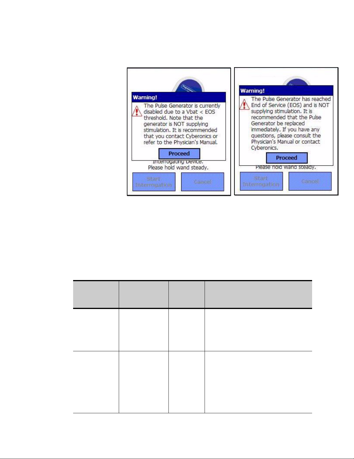
Figure 9. PULSE DISABLED and BATTERY STATUS
INDICATOR - EOS WARNING Screen
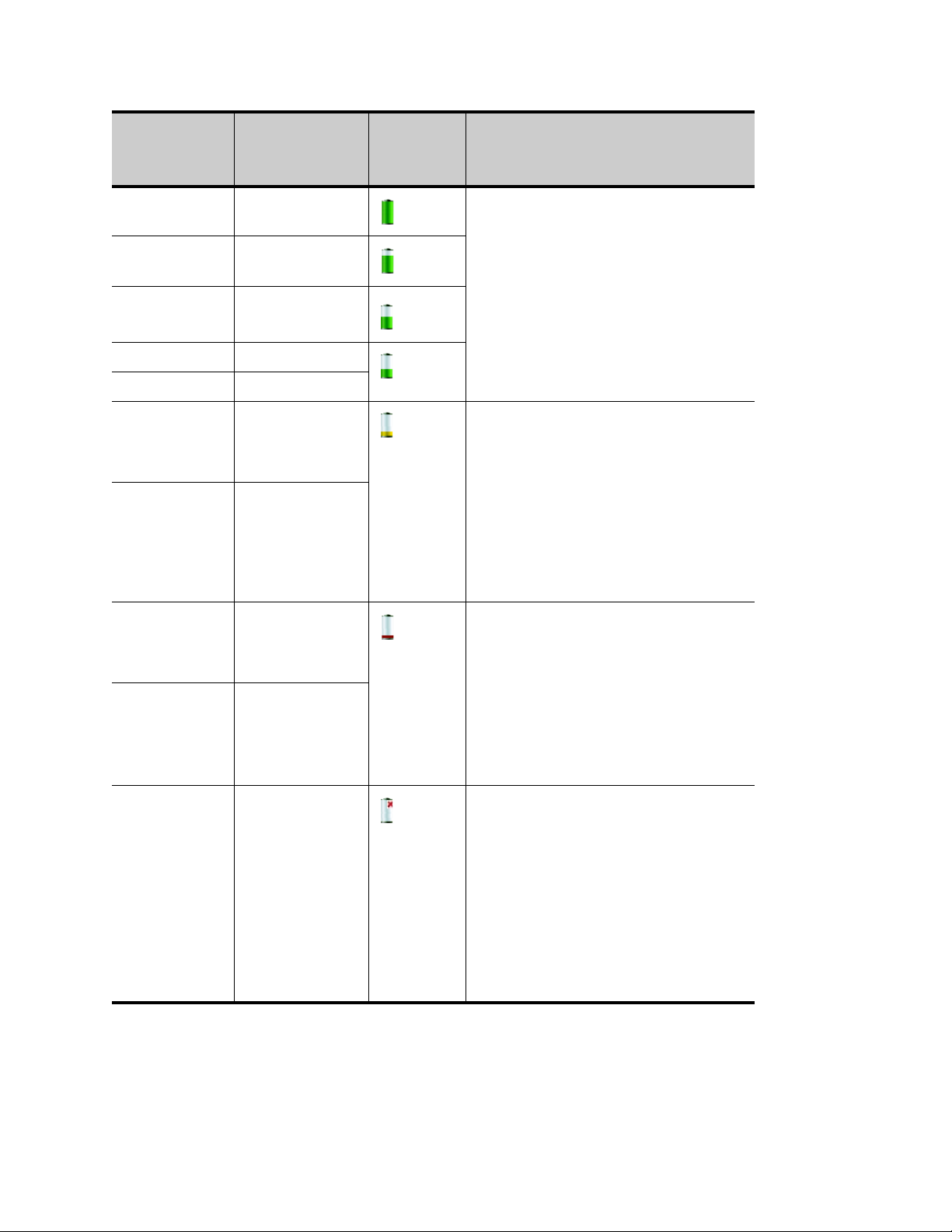
Table 1 shows the various indications of Pulse Generator battery level and
the associated recommendations.
Table 1. Pulse Generator Battery Level Indications and
Pulse
Generator
Model #
100/101/102 Battery
100/101/102 Battery
Estimated %
Battery Power
Remaining
measurement not
supported by
Generator
measurement not
supported by
Generator
Models 103, 104, 105
Recommendations
Battery
Icon
Displayed
None
displayed
None
displayed
Pulse Generator Battery Status /
Near EOS = No
The Pulse Generator battery level is good.
No warning message is displayed from the
Programming Software and no special
attention is required.
Near EOS = Yes
The Pulse Generator is nearing End of
Service (EOS). The Programming Software
will display a warning message indicating
this status upon completion of interrogation
or Diagnostics testing. It is recommended
that the Pulse Generator be replaced as
soon as possible.
Recommendations
26-0008-1100/5 (Worldwide) — 19 of 92
Physician’s Manual — VNS Therapy Programming Software (8.1)
Pulse
Generator
Model #
103/104/105 >75% to 100% IFI = No
103/104/105 >50% to 75%
103/104/105 >25% to 50%
103/104 >18% to 25%
105 >11% to 25%
103/104 >8% to 18% IFI = Yes
105 >5% to 11%
Estimated %
Battery Power
Remaining
Battery
Icon
Displayed
Pulse Generator Battery Status /
The Intensified Follow-up Indicator (IFI) has
not been set. The Pulse Generator battery
level is good. No warning message is
displayed from the Programming Software
and no special attention is required.
The Intensified Follow-up Indicator (IFI) has
been set for the Pulse Generator and a
warning message will be displayed by the
Programming Software to indicate this
status upon completion of interrogation or
Diagnostics testing. The Pulse Generator
battery has depleted to a level where more
frequent clinical monitoring is
recommended.
Recommendations
103/104 >0% to 8% N EOS = Yes
The Pulse Generator is near End of Service
(N EOS). The Programming Software will
105 >0% to 5%
103/104/105 0% EOS = Yes
display a warning message indicating this
status upon completion of interrogation or
Diagnostics testing. It is recommended that
the Pulse Generator be replaced as soon
as possible.
The Pulse Generator has reached End of
Service (EOS) and is NOT supplying
stimulation. The Programming Software will
display a warning message indicating this
status upon completion of interrogation or
Diagnostics testing. Immediate replacement
of the Pulse Generator is recommended. If
the Pulse Generator is not replaced, it will
eventually lose the ability to communicate
with the Programming Software.
20 of 92 — 26-0008-1100/5 (Worldwide)

Physician’s Manual — VNS Therapy Programming Software (8.1)
4.1. How to Program New Parameter Settings
The PARAMETER Screen shown in Figure 3 on page 15 is used to change
the Pulse Generator’s parameter settings. Table 2 shows the range of
possible settings for all parameters.
Table 2. Programmable Parameters for the Pulse
Generator
Programmable
Parameters
Output Current
Frequency
Pulse Width
Signal ON Time
Signal OFF
Time
0.0-3.5 milliamperes (in 0.25-mA steps)
1, 2, 5, 10, 15, 20, 25, 30 Hz
130, 250, 500, 750, 1,000 μsec
7, 14, 21, 30, 60 sec
0.2, 0.3, 0.5, 0.8, 1.1, 1.8, and
3 min; 5 to 60 in 5-min steps;
60 to 180 in 30-min steps
Settings
To change a parameter setting, follow these steps from the PARAMETER
Screen (Figure 3 on page 15):
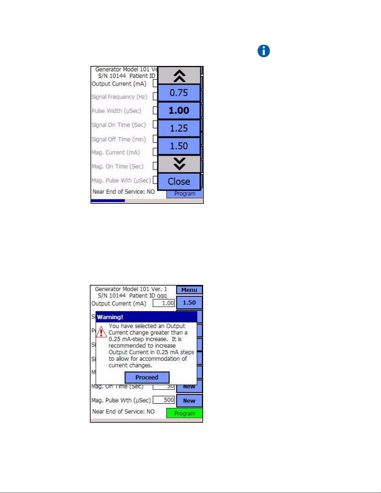
1. Tap the New button for the parameter you want to change. A pop-up
menu displays the range of possible values, with the current value
setting appearing in boldface type (see Figure 10). If there are values
greater than or less than those shown on the screen you can view them
by tapping the appropriate set of the double arrows. Look at the left
half of the screen and note that the parameter for which the value is
being changed is enabled (clearly visible) and the other parameters are
disabled (“grayed-out”). In the example in Figure 10, Output Current
is enabled and the other parameters are disabled. The value of 1.00 mA
has been selected for the Output Current parameter.
26-0008-1100/5 (Worldwide) — 21 of 92
Physician’s Manual — VNS Therapy Programming Software (8.1)
Figure 10. PARAMETER SETTINGS POP-UP Menu
2. Select the new target value for the Output Current by tapping the
desired value on the screen. If the target value selected is greater than
0.25 mA above the currently programmed value setting in the Pulse
Generator, an Output Warning will appear (see Figure 11 on page 22).
Note: LivaNova
recommends that during
the initial programming,
the output current be
programmed at 0 mA
and then slowly
increased by 0.25 mA
increments until the
patient feels the
stimulation at a
comfortable level. Even
patients who are
receiving replacement
generators should be
started at 0 mA Output
Current, followed by
incremental increases of
0.25 mA to allow for
reaccommodation to the
therapy.
Figure 11. OUTPUT WARNING
22 of 92 — 26-0008-1100/5 (Worldwide)
Physician’s Manual — VNS Therapy Programming Software (8.1)
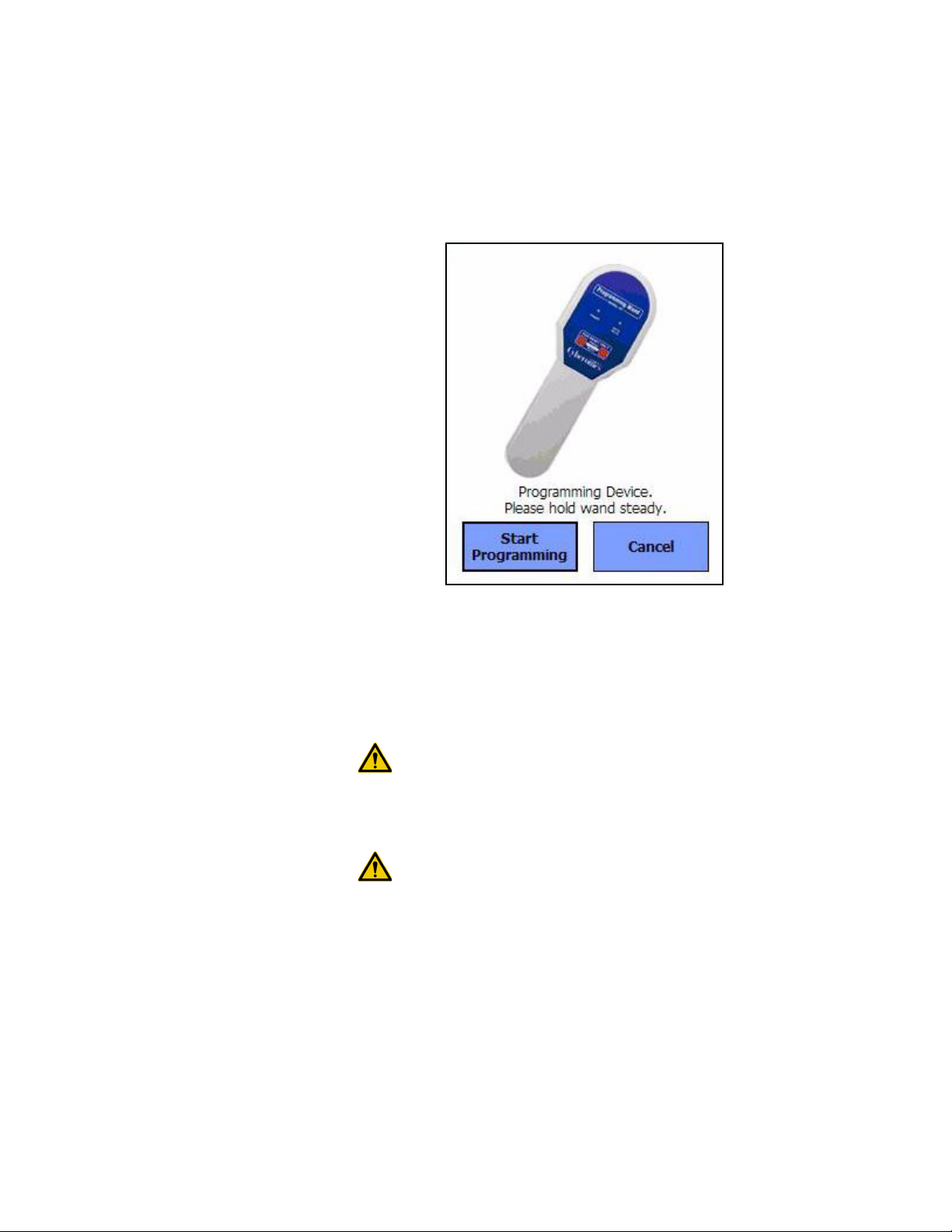
3. Tap the Program button, which turns green when a new parameter
value is selected, at the bottom of the PARAMETER Screen to access
the START PROGRAMMING Screen (see Figure 12).
Figure 12. START PROGRAMMING Screen
4. Place the Programming Wand over the Pulse Generator.
5. From the “Start Programming” screen, tap Start Programming to
program the new value or Cancel to return to the PARAMETER
screen menu.
Caution: For the Models 100, 101, and 102 Pulse Generators, do not
use frequencies of 5 Hz or less for long-term stimulation. These
frequencies always generate an electromagnetic trigger signal which
results in excessive battery depletion of the implanted Pulse
Generator; therefore, use these low frequencies for short periods of
time only.
Caution: Stimulation at a combination of high frequency (≥ 50 Hz)
and ON time ≥ OFF time has resulted in degenerative nerve damage in
laboratory animals. ON time ≥ OFF time can be simulated by very
frequent magnet activation. LivaNova recommends that stimulation at
these combinations of ranges be avoided.
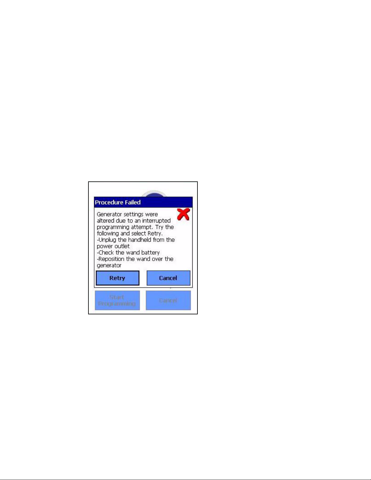
4.1.1. Partial Programming Due to Interrupted
Programming Operation
For Models 100, 101, and 102 Generators, each parameter is programmed
and verified individually during a programming event. Therefore, these
Pulse Generators can be partially programmed to unintended settings if the
communication between the Wand and the Pulse Generator is interrupted
during programming. If this occurs, the Programming Software displays a
26-0008-1100/5 (Worldwide) — 23 of 92
Physician’s Manual — VNS Therapy Programming Software (8.1)
warning message indicating that the procedure failed and device settings
were altered due to the interrupted programming attempt (see Figure 13 on
page 24). The warning message also indicates some troubleshooting
options and allows the user to retry or cancel the programming operation.
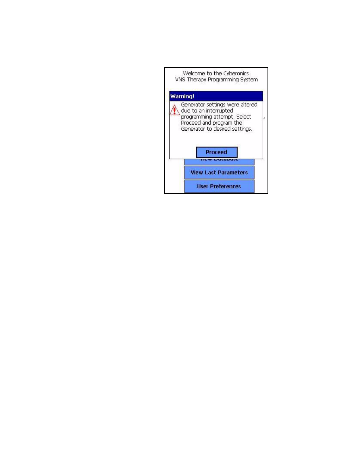
If the user selects Retry, the Programming Software will re-program the
Pulse Generator. If the user selects Cancel, the Programming Software
will default back to the START INTERROGATION screen (see Figure 2).
It is recommended that the Pulse Generator be interrogated immediately,
as this will verify the currently programmed settings. After completion of
the interrogation, the Programming Software displays a warning message
stating that device settings were altered due to the interruption (see
Figure 14) and allows the user to re-program the Pulse Generator to
desired settings upon selecting Proceed.
Figure 13. PROGRAMMING FAILED WARNING Screen
Models 100, 101, 102
24 of 92 — 26-0008-1100/5 (Worldwide)
Physician’s Manual — VNS Therapy Programming Software (8.1)
Figure 14. CHANGED SETTINGS PROGRAMMING
WARNING Screen
Models 100, 101, 102
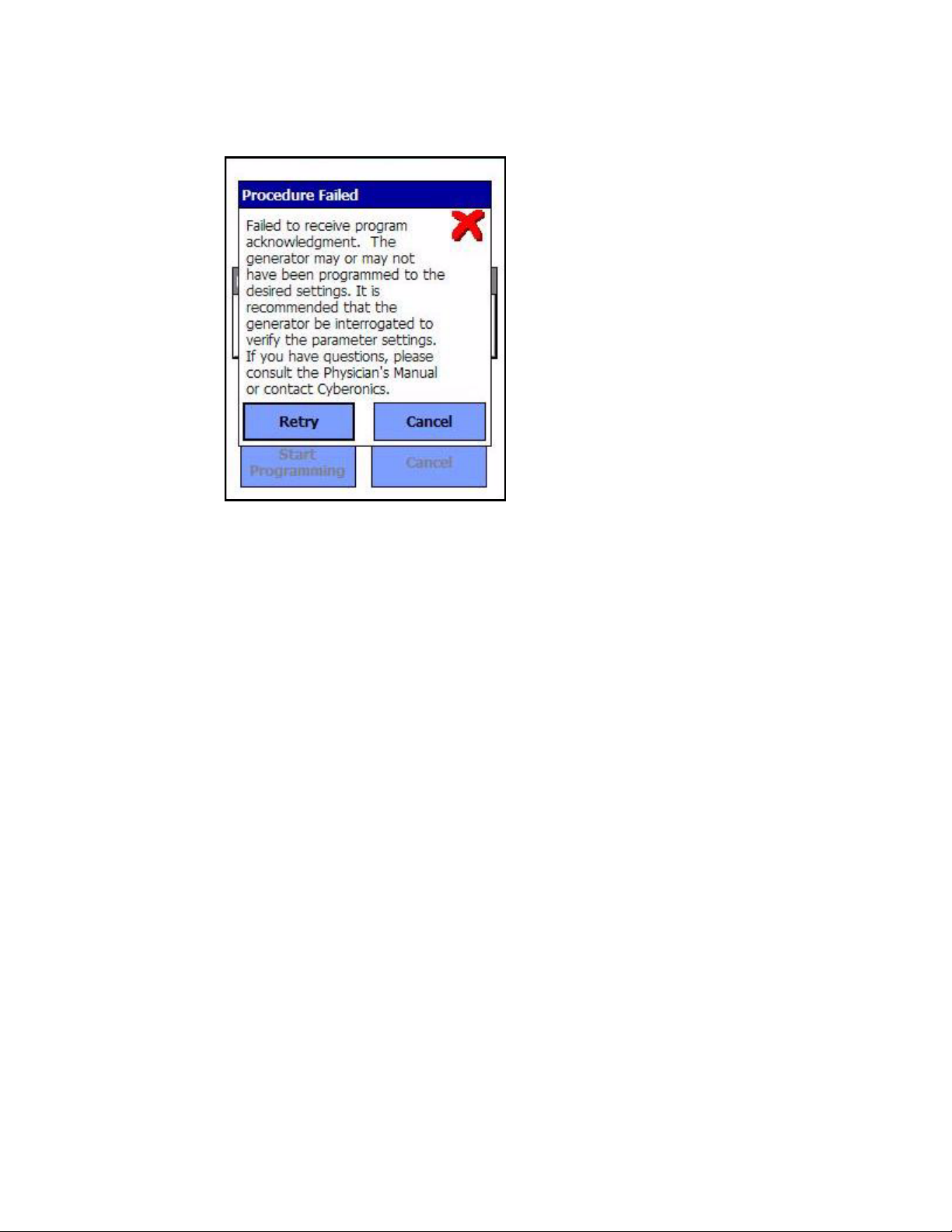
For Models 103, 104, and 105 Generators, the device parameters are
programmed and verified as a group during a programming event;
therefore, these Pulse Generators are not susceptible to partial
programming. If an interruption occurs during a programming step for
these Pulse Generators, the Programming Software displays a warning
message indicating that the procedure failed and allows the user to retry or
cancel the programming operation (see Figure 15 on page 26). If the user
selects Retry, the Programming Software will re-program the Pulse
Generator. If the user selects Cancel, the Programming Software will
return to the PARAMETER screen where the user can re-program the
Pulse Generator to desired settings (see Figure 3 on page 15).
26-0008-1100/5 (Worldwide) — 25 of 92
Physician’s Manual — VNS Therapy Programming Software (8.1)
Figure 15. PROGRAMMING FAILED WARNING Screen
Models 103, 104, 105
4.1.2. Cross-programming (applicable to Model 100, 101, and 102 Pulse Generators ONLY)
Models 100, 101, and 102 Pulse Generators are susceptible to an event
known as cross-programming, where parameter settings from one patient's
Pulse Generator are inadvertently programmed to another patient's Pulse
Generator. Cross-programming occurs when all the following conditions
are met:
1. Patient A is implanted with the same model Pulse Generator as Patient
B
2. Patient A's Pulse Generator was interrogated/programmed with the
Programming Software and the Programming Software is left on the
PARAMETER screen
3. Inactivity timeout has not expired, or is disabled
4. Patient B's Pulse Generator is programmed at the PARAMETER
screen in step 2 without first performing an interrogation
The result of the above scenario is that Patient B's output current and
magnet output current settings are programmed to Patient A's output
current and magnet output current settings, unless those parameters values
were changed as part of step 4. In addition, the Programming Software
database will incorrectly indicate Patient A to be programmed to setting
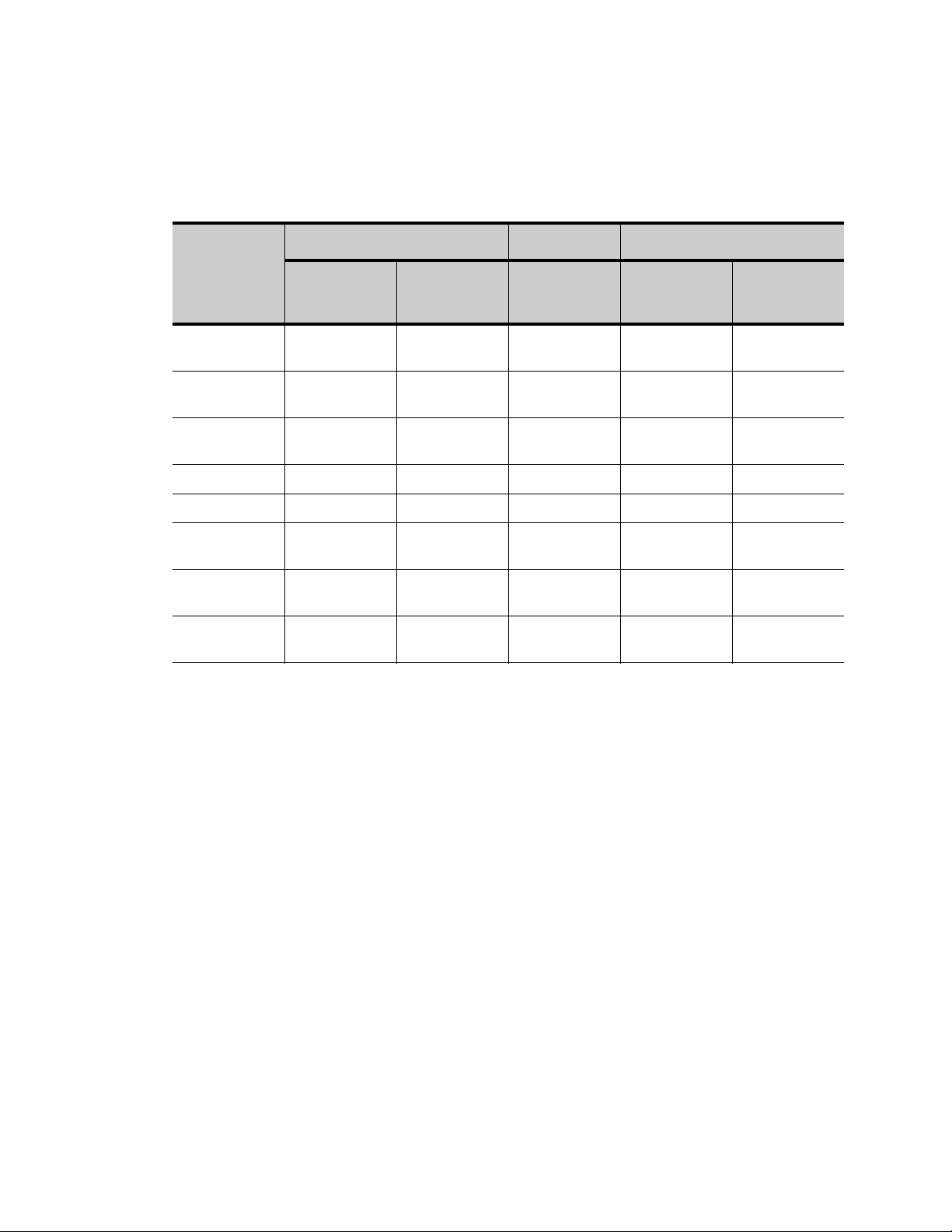
changes made in step 4. Table 3 gives an example of cross-programming
26 of 92 — 26-0008-1100/5 (Worldwide)
Physician’s Manual — VNS Therapy Programming Software (8.1)
and its effect on device parameters. The parameters marked with asterisks
indicate unintentionally altered or incorrectly displayed values.
Table 3. Cross-programming Example
After Step 2 At Step 4 After Step 4
Parameter
Output Current
(mA)
Frequency
(Hz)
Pulse Width
(µs)
On Time (s) 30 7 No change 7 30
Off Time (min) 5 1.8 3 3 3*
Mag. Output
Current (mA)
Mag. On Time
(s)
Mag. Pulse
Width (µs)
Patient A Final
Settings
0.25 0.75 No Change 0.25* 0.25
30 20 15 15 15*
250 500 No Change 500 250
0.5 1.00 No Change 0.5* 0.5
30 30 60 60 60*
500 500 250 250 250*
*Unintentionally altered or incorrectly displayed values.
Patient B Initial
Settings
Patient B
Intended Final
Settings
Patient B
Actual Final
Settings
Patient A Final
Settings in
Database
Due to the susceptibility of Model 100, 101, and 102 Pulse Generators to
cross-programming, LivaNova recommends that an initial and a final
interrogation be performed at each office visit for all VNS patients in order
to verify parameter settings.
4.2. PARAMETER Screen Menu
Tapping the Menu button at the right top of the PARAMETER Screen
causes the PARAMETER Screen Menu to be displayed, as shown in
Figure 16 on page 28.
26-0008-1100/5 (Worldwide) — 27 of 92

Physician’s Manual — VNS Therapy Programming Software (8.1)
Figure 16. PARAMETER Screen Menu
The functions available via this menu are explained in the following
paragraphs.
4.2.1. Interrogate Device
Interrogation of the Pulse Generator is required to reach the menu shown
in Figure 16. An Interrogate Device button is available here so you can
interrogate the device after each programming event. A post-programming
interrogation should be performed to ensure that the Pulse Generator was
programmed as desired.
4.2.2. Device Diagnostics
Tap the Device Diagnostics button on the PARAMETER Screen Menu to
display the DEVICE DIAGNOSTICS Menu (see Figure 17 on page 29).
28 of 92 — 26-0008-1100/5 (Worldwide)
 Loading...