

Page 1

LITTLE WONDER®
OPERATOR/OWNER MANUAL
AND
SAFETY INSTRUCTIONS
for
EDGER
©
2003, LITTLE WONDER, Div. Schiller-Pfeiffer, Inc.
Patents Granted in USA and Australia.
US Patent No. 5,826,667. Other US patents pending.
Design registrations Granted in
USA, Australia, Japan, Great Britain
Patent Pending on Cross-Blade System.
IMPORTANT MANUAL – DO NOT THROW AWAY
Manual always to be available for reference or instructing new operators
SUPERVISORS,THIS IS YOUR RESPONSIBILITY
IMPROPER USE
CAN CAUSE
SERIOUS INJURY
MAKE SURE THIS
MANUAL IS READ
AND CAREFULLY
UNDERSTOOD
BEFORE STARTING
OR OPERATING
THIS EQUIPMENT
Page 2

CONTENTS
INTRODUCTION . . . . . . . . . . . . . . . . . . . . . . . . . .2
SERVICE INFORMATION . . . . . . . . . . . . . . . . . . . .2
P
ARTS AND CONTROLS . . . . . . . . . . . . . . . . . . . . .3
SAFETY PRECAUTIONS . . . . . . . . . . . . . . . . . . . . .4
ASSEMBLING THE XTRA EDGER . . . . . . . . . . . . . .8
FUEL MIX AND FUELING . . . . . . . . . . . . . . . . . . .8
S
TARTING AND
STOPPING INSTRUCTIONS . . . . . .10
O
PERATING INSTRUCTIONS
. . . . . . . . . . . . . . . .11
A
IR AND
FUEL FILTER
MAINTENANCE . . . . . . .13
E
NGINE
IDLE SPEED ADJUSTMENT . . . . . . . . . .13
C
UTTER BLADE R
EPLACEMENT . . . . . . . . . . . . .14
L
UBRICATION OF
GEARS . . . . . . . . . . . . . . . . . .14
C
HECKING THE SPARK PLUG . . . . . . . . . . . . . . .15
C
HECKING THE MUFFLER . . . . . . . . . . . . . . . . .15
TROUBLESHOOTING TIPS . . . . . . . . . . . . . . . . . .16
P
ARTS LIST . . . . . . . . . . . . . . . . . . . . . . . . . . . .18
P
ARTS BREAKDOWN. . . . . . . . . . . . . . . . . . . . 19
E
NGINE PARTS
LIST . . . . . . . . . . . . . . . . . . . . .20
E
NGINE PARTS BREAKDOWN . . . . . . . . . . . . . . .21
B
ODY WORKSHOP MANUAL . . . . . . . . . . . . . . . .22
W
ARRANTY . . . . . . . . . . . . . . . . . . . . . . . . . . . .32
INTRODUCTION
This Manual contains operating, assembling,
safety and maintenance instructions for the
Little Wonder Gasoline Powered Xtra Edger.
This professional edging machine was designed to
the highest standards to ensure you many hours of
uninterrupted service.
Pay special attention to the safety precautions
outlined on pages 4 to 7. Allow only persons who
understand this Manual to operate the Xtra Edger.
To receive maximum performance and satisfaction
from your Xtra Edger, it is important that you read
and understand the maintenance and safety
precautions before using the edger. Contact your
Little Wonder dealer or the Little Wonder distributor in your area if you do not understand or cannot
carry out any of the instructions in this Manual.
S
ERVICE INFORMATION
Contact your authorized Little Wonder
dealer for service.
WARNING
As with any power tool, some special
safety precautions must be observed
to reduce the risk of personal injury.
Careless or improper use may cause
serious or even fatal injury.
▲
!
▲
!
SAFETY WARNINGS
THE PURPOSE OF SAFETY WARNING AND NOTES IN THIS MANUAL
IS TO ATTRACT YOUR ATTENTION TO POSSIBLE DANGERS AND THE
EXPLANATIONS WITH THEM DESERVE YOUR CAREFUL ATTENTION
AND UNDERSTANDING. THE SAFETY WARNINGS IN THIS MANUAL AND
ON THE XTRA EDGER DO NOT, BY THEMSELVES, ELIMINATE ANY
DANGER. THE INSTRUCTIONS OR WARNINGS THEY GIVE ARE NOT
SUBSTITUTES FOR PROPER ACCIDENT PREVENTION MEASURES.
▲
!
▲
!
▲
!
WARNING: Failure to obey a
safety warning can
result in injury to
yourself and others.
NOTE: Advises you of information
or instructions vital to the
operation or maintenance
of the equipment.
!
2
Page 3

The engine exhaust from this product contains chemicals
known to the State of California to cause cancer, birth defects or other reproductive harm.
13 Blade cover reduces the risk of flying
debris and direct contact with the feet or
hands.
10 Cross blade set rotates when engine speed
is increased above idle.
52 Wheel for moving and guiding edger.
27 Grass shield reduces flyback of stones
and foreign material.
68 Cross-brace attaches downwards on
handles
35, The handles of the Xtra Lawn
36 Edger are held by both hands.
50 The ON/OFF switch and throttle
trigger which increases speed of engine
for automatic safety clutch to engage and
thus rotate blade.
85 Handle nut for holding handles onto
housing (and adjusting anti-vibration of
handle).
71 Height adjustment for adjusting depth of
cutting blade.
PARTS AND CONTROLS
DANGER!
KEEP HANDS & FEET AWAY
ROTATING BLADE
DIRECTION OF ROTATION
WARNING
KEEP INSIDE OF BLADE GUARD CLEAN,
ESPECIALLY IN WET CONDITIONS. A CLOGGED
GUARD CAN SLOW DOWN OR STOP BLADE
ROTATION AND MAY CAUSE DAMAGE TO
AUTOMATIC SAFETY CLUTCH. ALWAYS OPERATE
BLADE AT HIGH SPEED WHEN EDGING.
3
Key #21
Key #22
Key #25
FIG 1
WARNING
● ALWAYS REPLACE FUEL CAP SECURELY.
● METAL PARTS OF ENGINE HOT DURING &
AFTER USE. DO NOT TOUCH.
WARNING - TO PREVENT SERIOUS INJURY
FOLLOW ALL SAFETY PRECAUTIONS IN OPERATOR MANUAL - IMPROPER USE CAN CAUSE SERIOUS OR FATAL
INJURY ● OBJECTS MAY BE THROWN OR RICHOCHET IN ALL DIRECTIONS - ALWAYS WEAR EYE PROTECTION
● KEEP BYSTANDERS AT LEAST 50FT (16M) AWAY ● ALWAYS WEAR EAR PROTECTION ● WEAR SNUG FITTING
CLOTHING ● MINORS SHOULD NEVER BER PERMITTED TO USE THIS EDGER ● WEAR STURDY SHOES WITH
NON-SLIP SOLES ● DO NOT LEND, RENT OR SELL THIS EDGER WITHOUT THE OPERATOR MANUAL.
(FORM No.43133)
▲
!
WARNING:
50
36
21
35
25
68
85
71
52
10
13
27
22
Page 4
Little Wonder’s philosophy is to continually improve
all of its products. As a result, engineering changes
and improvements are made from time to time. If
the operating characteristics or the appearance of
your Xtra Edger differs from those described in this
manual, please contact your Little Wonder dealer for
information and assistance.
WARNING
Like any power tool, the use of
any lawn edger may be dangerous.
It is important that you read, fully
understand, and observe the following
safety precautions and warnings.
Re-read this operator’s manual and
the safety instructions periodically.
▲
!
▲
!
WARNING
Careless or improper use of the
machine may cause serious injury.
Have your dealer show you how
to operate your Xtra edger.
▲
!
▲
!
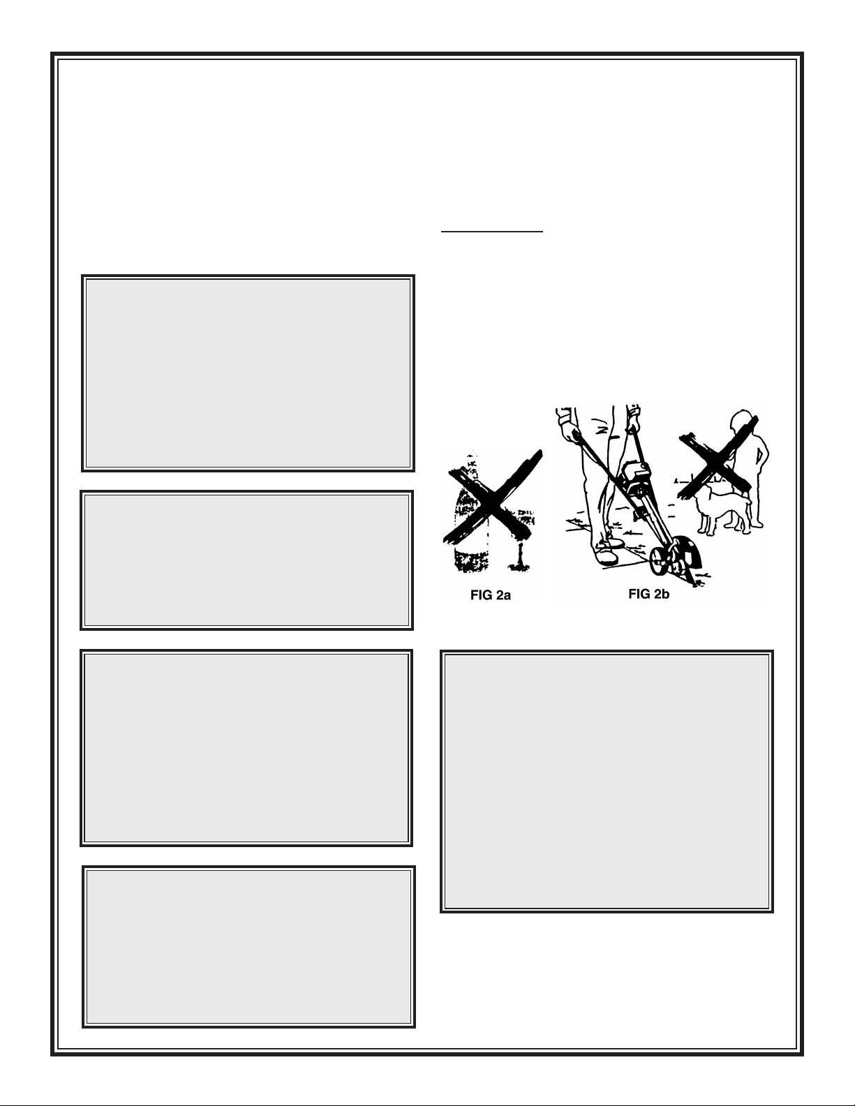
WARNING
The Xtra Edger must not be
operated by minors. Bystanders,
especially children and animals,
should not be allowed in the area
where a machine is in use
(at least 15 feet away) (Fig. 2b).
Never let the unit run unattended.
▲
!
▲
!
WARNING
Do not lend, rent or sell this
machine without the operator’s
manual. Be sure that anyone using
this unit understands the information
contained in this manual before use.
▲
!
▲
!
Safe use of an Xtra Edger involves:
1. The Operator
2. The Xtra Edger
3. The use of the Xtra Edger
T
HE OPERATOR
P
HYSICAL CONDITION
Operator must be in good physical condition and
mental health, and not under the influence of
any substance (drugs, alcohol, etc.) which might
impair vision, dexterity or judgement (Fig. 2a).
4
SAFETY PRECAUTIONS
WARNING
Prolonged use of any hand-held
powered machine exposing the
operator to vibrations may produce
whitefinger disease (Raynaud’s
phenomenon) or carpal tunnel syndrome.
These conditions reduce the hand’s
ability to feel and regulate temperature,
produce numbness and burning
sensations, and may cause nerve and
circulation damage and tissue necrosis.
▲
!
▲
!
Page 5

sunny conditions, always wear a hat and long
sleeve shirt for protection against skin cancers.
Use of a good brand of sunscreen cream is also
recommended on exposed skin surfaces.
Replace immediately broken or cracked blade
covers and grass debris deflector.
Never operate an Xtra Edger unless wearing
goggles or properly fitting safety glasses with
adequate top and side protection which comply
with ANSI Z 87.1.
Engine noise may damage your hearing. Wear
sound barriers (ear plugs or ear mufflers) to protect your hearing. Continual and regular users
should have their hearing checked regularly.
S
AFE FUELING
The Xtra Edger unit uses an oil-gasoline mixture
for fuel (see the chapter on “Fuel,” page 8).
Do not operate an Xtra Edger when fatigued.
Be alert - if you get tired while operating the
machine, take a break. Tiredness may result in
loss of control. Working with any power tool
can be strenuous. If you have any condition that
might be aggravated by strenuous work, check
with your doctor before operating the machine.
The Xtra Edger is equipped with vibrationreducing hand grips and main handle antivibration mountings. These are designed to
reduce the transmission of engine vibrations to
the operator’s hands. Replace hand grips and
mountings when worn or damaged.
The rubber handles do not guarantee that you
will not sustain whitefinger disease or carpal
tunnel syndrome. Therefore, continual and
regular users should monitor closely the
condition of their hands and fingers. If any
of the above symptoms appear, seek medical
advice immediately.
P
ROPER CLOTHING
Clothing must be sturdy and snug-fitting, but
allow complete freedom of movement (see Fig.
3). Avoid loose-fitting jackets, flared or cuffed
pants, or anything that could trip the operator.
Wear overalls or long pants to protect your legs.
DO NOT wear shorts. Use of gloves when
working with the Xtra Edger is recommended.
Good footing is most important. Wear sturdy
shoes with nonslip soles. DO NOT wear
sandals or operate with bare feet. In hot or
WARNING
Proper eye protection is a must.
The blade cover may not protect the
operator from all fast moving foreign
objects, even though the discharge is
directed away from the operator,
as ricochets and bouncebacks may
occur during lawn edging operations.
▲
!
▲
!
5
FIG 4
WARNING
Gasoline is an extremely flammable
and explosive fuel. Use extreme
caution when handling gasoline or
fuel mix. Do not smoke or bring
any fire or flame near the fuel.
▲
!
▲
!
Page 6

SAFE FUELING INSTRUCTIONS
Refuel outdoors only. Always switch off the
engine and allow it to cool before refueling.
Relieve fuel tank pressure by loosening fuel
cap slowly. Never remove fuel filler cap while
engine is running.
Select bare ground for fueling, then move at
least 10 feet from the fueling spot before starting the engine. Wipe off any spilled fuel before
starting your Xtra Edger and check for leakage.
Always tighten fuel filler cap securely after
fueling.
S
AFE STARTING
You should always inspect your unit before
starting it. Make sure the controls and safety
devices are working properly.
For specific starting instructions, see the
appropriate section of this operators manual.
Place the machine on firm ground or other solid
surface in an open area. Maintain good balance
and secure footing.
Failure to follow this procedure may result in
injury to hand or fingers or may damage the
starter mechanism.
S
AFE WORKING INSTRUCTIONS
AND
IMPORTANT ADJUSTMENTS
Never operate your machine if it is damaged,
improperly adjusted or not completely and
securely assembled. At correct idle speed, the
blade should not turn. Do not use the Xtra
Edger with incorrect idle speed; see the speed
setting instructions on page 13.
S
AFE MAINTENANCE, REPAIR AND STORING
Use only original Little Wonder replacement
parts for maintenance and repair. Use of parts
manufactured by others will void warranty
and/or may cause serious or fatal injury.
Follow the maintenance instructions in the
appropriate section of this manual. Any repairs
should be carried out by an authorized service
dealer.
WARNING
Always allow engine to cool before
refueling. Accidental spillage of gasoline
over hot engine could cause fire or
explosion to occur with consequent
possible disfigurement or fatal injury.
Wash and clean hands after fueling.
▲
!
▲
!
WARNING
The Xtra Edger is a one-person
machine. To reduce the risk of eye or
other injury from thrown objects,
ensure that bystanders are at least 50
feet away during use. Replace
immediately any worn or broken debris
deflector shield or blade cover. If
approached, release throttle trigger to
immediately deaccelerate the engine.
▲
!
▲
!
WARNING
When you pull the starter grip, do not
wrap starter rope around your hand.
Do not allow grip to snap back, but
guide starter rope slowly back to
permit rope to rewind properly.
▲
!
▲
!
6
WARNING
Always stop the engine, make sure that
the blade is stopped, and disconnect
the spark plug before adjusting blade
height, doing any maintenance or repair
work, or cleaning the unit or blade.
▲
!
▲
!
Page 7

Check fuel filler cap for leaks at regular
intervals. Use the specified spark plug and
make sure it and the ignition lead are always
in good condition.
Remember that the risk of forest or grass fires is
greater in hot weather.
Keep spark plug and wire connection tight and
clean. Spark plug electrode gap should be
checked with a feeler gauge at least every 50
operating hours and reset if necessary. Fit a
new spark plug if electrodes are badly pitted
or fouled with carbon build-up.
Store Xtra Edger in a dry, high or locked
location place and out of reach of children.
Before storing for a longer period, always empty
the fuel tank.
WARNING
A worn or damaged muffler is a fire
hazard and may cause loss of hearing.
Check to see that the muffler is in good
condition. The lawn edger must not be
operated if the muffler is not functioning
properly, is damaged, or has been removed.
In order to reduce the risk of fire, do not
modify or remove any part of the muffler
and ensure your spark arrestor screen
is not worn or broken.
▲
!
▲
!
Keep the space behind and beside the engine
clear at all times to allow for the escape of hot
and toxic exhaust fumes.
Operate your machine under good visibility and
daylight conditions only. Work carefully.
S
AFE
WORKING
CONDITIONS
When working with the Xtra Edger, always
wrap your fingers tightly around each handle.
Keep your hands in this position to have your
machine under control at all times. NEVER
attempt to operate the Xtra Edger with one
hand, as a loss of control may result in serious
or fatal injury.
Make sure the handle grips are in good
condition and free of moisture, pitch, oil or
grease. Use both hands, one on each handle,
to operate and control the lawn edger. Do not
overreach. Keep proper footing and balance at
all times.
WARNING
Never touch a hot muffler
as burns will result.
▲
!
▲
!
WARNING
Never store the machine with gasoline
inside a building where fumes may reach
an open flame or spark (e.g. gas or oil-fired
heater appliance, electric motor, etc.).
▲
!
▲
!
WARNING
Start and operate your unit
outdoors and in a ventilated area.
▲
!
▲
!
7
WARNING
Do not touch hot engine during
and immediatley after use as
you may burn yourself.
▲
!
▲
!
WARNING
Electrical shock. Never touch electrical
wires or components while the engine
is running. They are sources of high
voltage and can give you an electrical
shock. Replace immediately any
faulty tension lead or spark plug cap.
▲
!
▲
!
Page 8

ASSEMBLING THE XTRA EDGER
FUEL MIX AND FUELING
1. Fit cross brace (Key #68) to handles (Key #35 & 36) with brace touching the ground. Use 4
screws (Key #1) and 4 locknuts (Key #2) provided in packet.
2. Fit handle assembly to edger. Insert 150mm (6”) bolt through left handle, edger body and right
handle. Screw large wing nut (Key #85) on bolt (Key #31) so that bolt end is approximately flush
(level) with face of the center boss of the large wing nut. This allows handle “platform” to “float”
without vibration. DO NOT OVERTIGHTEN WING NUT.
3. Fit throttle (Key #50) to right handle (Key #36). Clip in throttle cable/ignition switch wire with
2 cable clamps (Key #60) attached to handle. THROTTLE CABLE FROM ENGINE MUST BE
FITTED UNDER HANDLE. DO NOT LOOP OVER HANDLE.
8
WARNING DANGER
FUEL IS EXTREMELY FLAMMABLE. HANDLE IT WITH CARE.
KEEP AWAY FROM IGNITION SOURCES.
DO NOT SMOKE WHILE FUELING YOUR EQUIPMENT.
▲
!
▲
!
FIG 6
60
50
31
85
85
1
35
2
36
68
Your Little Wonder Xtra Edger is powered by a
commercial, two-stroke, air cooled engine
which requires a fuel mixture of gasoline and
two-cycle oil.
Use a mixture of 50 parts unleaded regular
gasoline and 1 part two-cycle oil (50:1). Use
branded 89 octane unleaded gasoline or gasohol
(maximum 10% ethyl alcohol, or 15% MTBE,
no methyl alcohol.)
Page 9

Here’s how to mix the oil with the gas:
1. Pour 1/2 gallon of the gasoline into a safe
one gallon container. Do not mix the fuel
and oil in the engine fuel tank.
2. Add 2.6 ounces (50:1 ratio) of two-cycle
engine oil to the gasoline and mix. Then
add the other 1/2 gallon of gasoline.
3. Screw the cap onto the gasoline can.
Then swirl the can to blend the oil and gas.
4. Carefully pour the fuel mix into the Xtra
Edger’s fuel tank. After putting the fuel
tank’s cap back on, wipe up spilled
fuel from tank and gasoline can.
IMPORTANT:
Two-cycle fuel separates and ages. Do not mix
more than you will use in a month. Using old
fuel can cause difficult starting or engine
damage. Shake fuel container to thoroughly
mix fuel before each use. Do not attempt to run
your engine on gasoline only; this will cause
engine failure and void engine warranty.
Need pre-measured engine oil? Contact your
local authorized Little Wonder dealer.
Remember...
• Always mix two-cycle oil with gasoline
before fueling your edger. Never, ever run
your Edger on gasoline alone. This will ruin
your engine and void all warranties.
• Always use a clean gas can and always use
unleaded gas.
• Never try to mix the oil and gasoline in the
engine fuel tank.
• Always mix oil and gas in the proper
proportions: 2.6 ounces of two-cycle engine
oil to one gallon of unleaded gasoline.
IMPORTANT NOTE:
DO NOT use old or stale oil/gasoline
mixture. Always use the proper
oil/ gasoline mixture. If you do not,
your engine will suffer rapid,
permanent damage and you will
void the engine warranty.
9
WARNING DANGER
Pressure may build up in the canister. Remove fuel cap slowly
to avoid injury from fuel spray. Replace fuel cap securely.
Clean the fuel cap and canister from time to time.
Take care when handling gasoline. Avoid direct
contact with the skin and avoid inhaling fuel vapor.
Change fuel pickup filter at least once every year or more frequently, depending on use.
Before fueling, clean the filler cap and the area around it to ensure that no dirt
falls into the tank. Never mix the gasoline and oil in the fuel tank of the engine.
Always allow engine to cool before refueling. Accidental spillage of gasoline over a hot
engine could cause fire or explosion to occur. See Page 6 - Safety Precautions, Fueling.
Fill or add fuel to the tank only when the edger is in a horizontal position as shown
(Fig. 7). Allow engine to cool down for at least 5 minutes before adding fuel.
▲
!
▲
!
FUEL MIX
Page 10

STARTING AND STOPPING INSTRUCTIONS
1. Place lawn edger on ground in horizontal
position (see Fig. 9C). Be sure the ignition
switch is “ON.” Pull switch toward
operator to turn ON. Switch is located
on right side of trigger (see Fig. 8).
2. COLD START: Move choke lever up to
start (closed) position (Fig. 9A). Press and
release primer 3 or 4 times until the fuel
flows into the clear tube (Fig. 9B). Place
one foot on the cross brace. Make sure you
have a firm footing. Hold down engine
with left hand and with right hand, pull the
starter grip slowly until you feel it engage and then give it a fast pull (Fig. 9C).
Do not pull out starter rope more than 26”
(65 cm) - it might break.
3. Stand between handles to start. Do not let
starter grip snap back. Guide it back slowly
so that the starter rope can rewind slowly.
4. PULL THE STARTER ROPE BRISKLY
until you hear the engine sound like it
wants to run or runs then stops (normally
1-5 pulls).
5. Open choke gradually (open position,
Fig. 9A) to allow engine to run.
10
NOTE: In warm temperatures or with hot
engine, this step may not be necessary.
6. HOT OR WARM START: (Engine has
already been started and warmed up.)
Switch ignition “ON.” Pull starter until
engine runs.
WARNING
The blade will rotate when engine is
idling fast or when engine is cold).
TO STOP ENGINE move ignition switch
forward into the “OFF” position (Fig. 8).
▲
!
▲
!
FIG 8
FIG 9C
FIG 9A
FIG 9B
Page 11

NOTE: A built-in automatic centrifugal clutch
disengages the blade from rotating at engine
idle speed. The clutch engages the blade when
the engine speed is increased.
7. Throttle trigger (engine accelerator control)
is operated by pushing down interlock with
thumb and pulling on trigger (Fig. 8).
8. FLOODED ENGINE: (Engine will not
start.) If smoke or fuel comes from exhaust
and engine will not start.
i. Check that ignition switch is “ON,”
CHOKE LEVER is on RUN position.
ii. Pull starter rope up to 10 times to clear
engine of fuel so it can start.
iii. If engine has excessive fuel that cannot
be cleared by i and ii above, remove
spark plug from engine and from spark
plug terminal, crank engine to clear
excess fuel, wipe and dry spark plug of
all fuel, re-install spark plug and
terminal, and restart as above.
IMPORTANT: After 1 hour of use, tighten all
screws (especially 9 screws around gear case).
Check after every 20 hours of use.
9. To stop motor, push switch slide on throttle
trigger side forward.
Anti-Vibration (AV) Adjustment
Handle nut can be tightened to mark on knob
to obtain best AV effect to reduce handle
vibrations.
During Break-In Period
A factory-new machine should not be run at
high revs (full throttle) without any load. This
avoids unnecessary wear during the break-in
period. As all moving parts have to set during
break-in period, frictional resistances in the
engine are greater during this period. Engine
develops its maximum power after about 5 to 15
tank fillings.
After Finishing Work
Storing for a short period: Keep the unit in a
dry place until you need it again. Do not store
where open flame or electrical machinery is
operating.
Storing for a long period: Drain the fuel tank
and run engine until carburetor is dry.
OPERATING INSTRUCTIONS
1. The Xtra Edger is very easy and simple to
use. For some people, it may take a few
edgings to become an expert.
2. Thoroughly inspect the area where the
edger is to be used and remove all stones,
sticks, wires and other foreign objects.
3. Adjust blade height (Fig. 10). With a
new blade, try the second hole closest
to operator.
11
WARNING
Only operate unit when moving forward.
DO NOT operate walking backwards,
as you may trip, fall and injure yourself.
▲
!
▲
!
WARNING
TO AV OID PERSONAL INJURY,
NEVER CARRY THE EDGER WHILE
THE ENGINE IS RUNNING.
Stay clear of the rotating blade.
Stop the engine prior to making
adjustments and cleaning.
▲
!
▲
!
FIG 10
Page 12

12
FIG 12A
FIG 11
10. Sideways Tilting: Lower either left or right
handle to achieve angle cutting (Fig 12D).
11. Clutch: The Xtra Edger is equipped with
a centrifugal clutch. DO NOT run edger at
low speeds or, if blade is jammed, at high
speeds as clutch shoes will prematurely
wear out and cause damage.
FIG 12B
FIG 12C FIG 12D
4. With both arms fully extended downwards
(see illustration on front cover), hold both
handle grips firmly. With the engine
running, pull the throttle trigger to increase
engine speed.
5. If blade is not deep enough, or if digging
is too deep, adjust blade height or slightly
raise or lower handles to suit depth required
(Fig. 11). However, it is always more
comfortable and relaxed to have arms fully
extended downwards.
6. As cutting action begins, push the lawn
edger forward so that the blade can cut the
edge as you move forward (Fig. 12A).
7. Continue at a moderate pace until you are
familiar with the controls and the handling
of the Xtra Edger.
8. If blade jams or stops in the ground
(Fig. 12B), lower handles or pull back unit
and recommence. Control engine and
cutting speed to suit work being done.
When cutting efficiently, engine speed
should be full throttle under load.
9. Edging along Concrete edge: For position
of blade, align edge guide on top of blade
cover with edge of concrete. If blade hits
concrete, lower handles and re-position
blade at side of concrete. Even with the
grass growing over the concrete and you
cannot see the edge, you can feel the edge
of the concrete with the rotating blade by
slightly sideways tilting the handles of
the edger away from the concrete so that
the blade tilts towards the concrete and
touches or “kisses” the concrete edge and
acts as a guide (Fig 12C). Edger blades are
made from high tensile hardened spring
steel and will last a long time. Once the
edge is established the second and
subsequent times around are very fast
especially when the blade kisses or touches
the concrete edge (Fig 12C).
Page 13

13
FIG 13
FIG 15
FIG 16
FIG 14
AIR FILTER MAINTENANCE
NOTE: Clean and re-oil the air filter every 5
hours of operation or daily. The air filter is one
of the most important areas to maintain. If it is
not maintained, you will void the warranty.
Before cleaning, make sure the unit is turned off.
1. Wash the two filters in detergent and water
(Fig. 13). Rinse the filter thoroughly and
allow it to dry.
2. Apply enough clean two-cycle oil or
SAE 30 oil to saturate the filters when
squeezed. Squeeze the filters to spread the
oil and to remove excess oil (Fig. 13).
Reinstall the mesh screen and plate screen,
two air filters and air filter cover (Fig 14).
NOTE: If the unit is operated with a dry or
dirty filter or without the air filter and/or
carburetor/air filter cover, you will void
the warranty.
F
UEL FILTER
When the engine runs short of fuel supply and
the tank has gasoline in it, clean the fuel filter
for blockage (Fig. 15).
T
HROTTLE CABLE
The normal play is .040” to .080” when
measured at the carburettor side. Re-adjust with
the cable adjustor as required (Item 1, Fig. 16).
NOTE: Throttle cable wire is not to be pulled
tight (against trigger throttle). Trigger to have
small initial movement before it pulls cable and
carburettor throttle lever.
E
NGINE IDLING SPEED
It is normal that the engine keeps running without the blade rotating, when the throttle lever is
released. When the engine speed is too high or
too slow, readjust the idle set screw
(Item 2, Fig. 16).
Page 14

BLADE REPLACEMENT
1. Stop engine. Clean area around dust cover
and pry out with screwdriver (Fig. 17).
2. Through dust cover hole, place 14 mm
socket. On blade end of shaft, place 18 mm
wrench on blade nut (Fig. 18).
3. Unscrew nut (Key #40) counter-clockwise
(normal right hand thread).
4. Remove one small washer (Key #16), one
large washer (Key #17) and one straight
then one formed blade (Key #10). Before
installing blade and washers, clean all grit
and grease. Assemble these parts clean and
dry. Fit large washer (Key #17), new
blades (Key #10) with flat blade on inside
then overlapping formed blade, large
washer (Key #17), one small washer
(Key #16), and nut (Key #40) (Fig. 19).
Tighten nut.
5. Clean plastic dust cap (Key #72) and
housing (Key #80); press back by gently
tapping into place. Clean inside blade cover of
any built up dirt.
L
OOSE BLADE
Follow steps 1 and 2 of Blade Replacement and
tighten nut clockwise.
L
UBRICATION OF GEARS
The oil in the gear case should be filled up
according to use by adding light, free-flowing,
lithium-based grease (P/N 100130) through fill
screw hole in casing (Fig. 17). Use a suitable
filling gun or squeeze grease pack (P/N
100130). Remove bleed screw to allow grease
to eject, indicating gear box is 3/4 full. Refit
bleed screw and push in 3-4 more pumps. Refit
fill screw.
WARNING
DO NOT RUN ENGINE WITHOUT
BLADE TIGHTENED TO BLADE SHAFT
AS GEAR DAMAGE WILL OCCUR.
▲
!
▲
!
WARNING
USE ONLY LITTLE WONDER
BLADES (P/N 100105). Other blades
have larger size holes (1/2”) which
will cause out-of-balance vibrations
which will damage unit and cause injury.
▲
!
▲
!
14
FIG 17
FIG 18
FIG 19
FIT BLADES AT
RIGHT ANGLES.
2 SPIGOTS ON EACH
BLADE FIT INTO HOLES OF OTHER BLADE
FITTING INSTRUCTIONS
40
17
16
10
17
Page 15

CHECK THE
SPARK
PLUG
If engine is low on power, difficult to start
or runs poorly at idling speed, check the spark
plug.
•Allow engine to cool down.
• Remove spark plug.
• Clean dirty spark plug.
• Check electrode gap - it should be 0.02”
(0.5 mm) (Fig. 20).
• Rectify faults which have caused fouling of
spark plug. Possible faults include:
- Incorrect carburetor setting.
-Too much oil or wrong type of oil in
fuel mix.
- Old fuel mix.
-Dirty air filter.
- Unfavorable running conditions (e.g.
operating at part load).
Do not clean the spark plug in an abrasive
grit spark plug cleaner, as expensive damage to the engine could occur through loose
grit damaging chrome in cylinder bore.
Fit a new spark plug after approximately 100
operating hours or earlier if electrodes are
badly eroded (recommended type: NGK
BPMR7A or Champion RCJ-6Y).
NOTE: Using spark plugs other than those
designated may result in the engine failing to
operate properly or in the engine becoming
overheated and damaged.
C
HECKING EXHAUST MUFFLER
Tighten exhaust screws. If exhaust gasket is
leaking, replace gasket. If the engine is low
on power, check the muffler. Allow motor to
cool down. Remove and scrape out excess
carbon (Fig. 21) on both inlet and exit exhaust
or have this done by a service dealer. Replace
exhaust spark arrestor if worn, broken or
blocked (Fig. 22).
15
0.5mm
0.02”
Resistor Spark
Plug
FIG 20
FIG 22
FIG 21
If debris causes blockage around the
intake air cooling vent or between the
cylinder fins, it may cause the engine to
overheat, and that in turn may cause
mechanical failure on the part of the Xtra
Edger. Remove air deflector to clean.
Page 16

PROBLEM CAUSE ACTION
Engine will not run. Ignition switch is “OFF”
Empty fuel tank
Primer bulb was not pushed enough times
Engine is flooded
Turn switch “ON.” Push down.
Fill fuel tank.
Press primer bulb fully and slowly
5 times.
Use starting procedure without
using choke. See page 11.
Engine runs rough
or is hard to start.
Carburetor/crankcase/cylinder
gaskets/crankshaft seal leaking
Damaged engine parts
Tighten screws.
Replace gaskets with a sealant and
tighten screws. Replace crankshaft
seal, damaged parts.
Engine lacks power
or stalls when cutting.
Dirty air filter
Blocked muffler
Clean or replace air filter.
Clean muffler
Cutting blade
does not turn
when operating.
Blade cover filled with dirt/grass.
Clutch slipping.
Loose blade nut.
Clean.
Cut less depth. Check clutch.
Tighten nut. See page 14.
Gear case leaking. Loose screws
Broken “O” ring
Tighten.
Replace.
Noisy gears. No heavy oil in gear case.
Loose blade nut or gear adjustment
incorrect.
Refill. See page 14.
Reassemble parts correctly.
TROUBLESHOOTING TIPS
16
Page 17

N
OTES
17
Page 18

LITTLE WONDER XTRA EDGER PARTS LIST
18
KEY # PART # DESCRIPTION
1 100500 Screw M5 x 36mm
2 100501 Nut Nyloc 5mm
3 100100 Ball Bearing 6203RS
5 100101 “O” Ring
6 100102 Felt Seal
7 100103 Adjusting Arm Spring
9 100503 Set Screw 5/16 x 5/8” BSW
10 100105 Cross-blade Set
11 100504 Adjusting Arm Bolt and Pin
12 100106 Blade Cover Support
13 100107 Blade Cover
14 100108 Blade Drum
15 100109 Blade Shaft Drive
16 100506 Blade Washer Small (hardened)
17 100507 Blade Washer Large
18 100110 Crown Gear L/E
20 100111 Crown Gear Spacer
21 100604 Warning Label “Hot Motor”
22 100605 Warning Label “Blade Cover”
25 100607 Warning Label on Left Handle
26 100112 Grass Shield Spring
27 100113 Grass Shield
28 100114 Grass Shield Cover
29 100115 Grass Shield Limiter
30 100116 Grass Rubber Flap
31 100509 Handle Bolt 5/16 x 6” Cup Head
KEY # PART # DESCRIPTION
32 100117 Handle AV Rubber
33 100118 Handle End Plug (small)
34 100119 Main Body Shield
35 100120 Main Handle LH (Pro)
36 100121 Main Handle RH (Pro)
37 100510 Nut 5/16 Nyloc
39 100512 Nut Nyloc 3/8
40 100513 Nut 12mm x 1.75
41 100514 Pinion Washer .020”
42 100122 Pinion L/E
43 100515 Screw M5 x 39 Short/thread
44 100516 Spring Pin 3/16 x 11/16
45 100517 Screw M5 x 38
47 100519 Screw M5 x 16
49 100521 Screw Self Threading M5 x 20
50 100123 Throttle Trigger Assembly
51 100522 Washer Blade Cover
52 100124 Wheel Complete
53 100523 Wheel Axle Bolt 3/8 x 4 1/2
54 100125 Wheel Axle Spacer 49mm Z/P
55 100126 Wheel Axle Tube 39mm
56 100127 Wheel Support Arm
57 100524 Wheel Support Axle Bolt 3/8 x 2.5”
58 100128 Height Adjust Shaft Spacer 35mm
59 100525 Washer 3/8 x 20mm
60 100129 Throttle Wire Clamp
KEY # PART # DESCRIPTION
61 100130 Grease & Dispenser
62 100700 Pro Operators Manual
67 100132 Pro Clutch Drum
68 100133 Pro Handle Cross Brace
69 100134 Pro Clutch Cover
71 100136 Pro Height Adjust Handle
72 100137 Pro Dust Plug
73 100138 Cable Tube
74 100526 Screw 25mm x 6
75 100527 Washer
76 100139 Main Drive Shaft
78 100141 Handle Grip
79 100142 Switch Wire Pro
80 100143 Pro Main Body
81 100144 Pro Main Body Cover
82 100145 Handle AV Rubber Plate
83 100900 Pro G34L Motor
84 100146 Throttle Cable
85 100147 Knob Assembly
86 100148 Debris Deflector Assembly
87 100149 Engine Air Deflector
88 100528 Spacer
89 100150 Muffler Shield Plug
90 100603 Shaft Label
91 100602 Recoil Label
Page 19

19
LITTLE WONDER XTRA EDGER PARTS BREAKDOWN
Page 20

20
Page 21

21
LITTLE WONDER
X
TRA E
DGER
ENGINE PARTS
BREAKDOWN
Page 22

B
LADE REPLACEMENT
1. Stop engine. Clean area around dust cover and
pry out with screwdriver (Fig. 1A).
2. Through dust cover hole, place 14mm socket.
On blade end of shaft, place 18mm wrench on
blade nut (Fig. 1C).
3. Unscrew nut counter-clockwise (normal right
hand thread).
4. Remove one small washer, one large washer
and one straight and one formed blade. Before
fitting blade and washers, clean all grit and
grease. Assemble these parts clean and dry.
Fit large washer, new blades with flat blade on
inside then overlapping formed blade, large
washer, 1 small washer, and nut. Tighten nut
(Fig. 1B & 1C) to 15-20 ft. lbs. or hand tight.
F
ITTING NEW BLADE SHAFT
5. Remove blades, washers, blade drum, and felt
seal using wrenches as shown (Fig. 1A, 1B,1C).
6. Hold unit as shown and tap shaft through using
a 3/8 bolt or similar (Fig. 2A) so that bolt
READ ALL THIS INFORMATION BEFORE COMMENCING, SO YOU BECOME
FAMILIAR WITH SEQUENCE OF REPAIRS. CLEAN ALL PARTS BEFORE REASSEMBLY.
LITTLE WONDER® XTRA E
DGER
Body Workshop Manual
BLADE REPLACEMENT • FITTING NEW BLADE SHAFT
REPLACING CLUTCH DRUM HOUSING OR GEARS
WARNING
Use only Little Wonder Blades.
Other blades have larger size holes
(1/2”) which will cause out-of-balance
vibrations which will damage unit
and can cause injury. The use of
incorrect blades will void warranty.
▲
!
▲
!
22
FIG 1C
FIT BLADES AT RIGHT ANGLES.
2 SPIGOTS ON EACH BLADE FIT
INTO HOLES OF OTHER BLADE
FITTING INSTRUCTIONS
FIG 1A
FIG 1B
Page 23

replaces shaft and maintains alignment and
contains washers, spacer and gear in housing DO NOT TURN HOUSING OVER.
7. Carefully push new blade shaft up into bearing
and tap through carefully so washers, crown
gear and spacer remain in position and the 3/8
bolt is pushed out (Fig. 2B).
8. When through, turn assembly over and drive
blade shaft through so head of shaft is up
against inner bearing shoulder.
9. Reassemble all parts (Fig. 1B and 1C), fit blade
and tighten up to 15-20 ft lbs or hand tight.
Head of blade shaft must pull up tight against
inner race,
otherwise blade will become loose during use.
NOTE: If shaft is difficult to knock out, remove
complete main body bearing cover housing
(see following para. 13 and Fig. 7).
R
EPLACING CLUTCH DRUM, CLUTCH HOUSING
OR
GEARS
10. Remove blade cover wheel assembly and
handles, leaving throttle connected to engine.
Remove engine from clutch housing using a
10mm wrench or socket or ratchet (Fig. 3).
R
EMOVING CLUTCH DRUM
11. If not overtightened by heavy work, it may be
possible to remove by holding blade in vice
(Fig. 5) or hold firmly pushing blades on
concrete or wooden floor as shown (Fig. 5A)
and ratcheting off counter-clockwise using hex
socket. Replace with new clutch drum.
23
WARNING
This method could unscrew
pinion, resulting in shaft not
being able to be turned. If
over-tight, proceed as follows.
▲
!
▲
!
FIG 3
FIG 4
FIG 5
SCREW ON CLUTCH DRUM
(Note: single large spacer between
hub and bearing)
CLUTCH
HOUSING
P/N 100134
FIG 5A
HOLD
DOWN
Page 24

12. Remove bearing holding screw (A), self
tapping clutch housing locating screw (B)
and loosen 2 x 5mm screws (C) (see Fig. 6).
13. Remove 3 screws, blade support plate and one
self-tapper on blade cover. Remove 6 screws
(D) (Fig. 6) holding main housing bearing
cover. Fit blade loosely and with a soft hammer, holding housing up, strike as illustrated
until housing pops out (see Fig. 7).
14. Heat housing bearing area (E) on both sides of
casing (Fig. 8) where shown with an air heat
gun if available to make pinion removal easier.
Using a screwdriver, lever pinion back, turn
screwdriver on edge to force back further (Fig.
9A & B).
NOTE: Position of screwdriver and direction
to lever.
15. With a copper or brass punch (a 7/16” brass or
copper shaft about 10” long), hold housing and
tap pinion out (Fig. 10).
BE CAREFUL: On the last tap, the pinion and shaft
could move out very quickly and if the drum hits any
object, it could bend. Use an obstacle of cloth to
prevent this.
16. Hold shaft in vice between two pieces of
aluminum so as not to damage, and unscrew
clutch drum counter-clockwise (Fig. 11). Re-fit
new clutch drum. On Pro Model, note 10mm
long spacer between metal hub and bearing.
Use a 13/16” (21mm) AF socket.
24
A
B
D
C
FIG 6
FIG 7
WARNING
DO NOT use STEEL drift as punch,
as you will damage the pinion teeth.
▲
!
▲
!
FIG 8
FIG 9A
FIG 9B
FIG 10
Page 25

REPLACING CLUTCH HOUSING
17. To replace clutch housing, remove clutch drum
(Fig. 11), tap shaft through housing (Fig. 12)
and slide off bearing and clutch housing.
Replace with new housing, reinstall bearing,
spacer and clutch drum. Place clutch drum
housing on top of jaws of vice and carefully tap
down (as shown in center of hex nut - not the
drum, as you could distort same) until bearing
bottoms into housing (Fig. 13).
R
EMOVING PINION
18. To remove pinion, grip shaft just behind
bearing in jaws of vice. Use soft aluminum in
jaws to prevent damage and unscrew pinion
counter-clockwise (normal thread) with vice
grips. If tight, heat to break loctite seal and
replace if pinion is worn. Replace new pinion,
making sure it is tight up to spacer washer (P/N
100514, Fig. 15) and does not move
(see Fig. 16).
A
SSEMBLING MAIN H
OUSING
19. Place oil resistant gasket sealant (e.g.
Fullerprene 303) around bearing (Fig. 16).
Heat up bearing area E with air gun if available.
20. Lock up a 3/8 bolt or a 10mm round brass or
steel in vice jaws so it can be used as a mandril.
Heat bearing area E with an air gun if available
(Fig. 17) and line up lug on clutch housing
(Fig. 18A) with inner recess on main housing
and place center of clutch drum over mandril in
vice, tap housing down until it bottoms (Fig.
18B, 18C). DO NOT allow drum to be hit, only
centre of hex at end of shaft as shown, otherwise drum could distort and run out of round.
25
FIG 12
FIG 11
FIG 13
FIG 15
FIG 16
FIG 17
FIG 18A FIG 18B FIG 18C
Page 26

Fit pinion bearing locating screw (43) and leave
nut loose (A). Using a screwdriver, lever
pinion firmly back to bearing locating screw
and tighten nut (Fig. 19B).
NOTE: If this is not done, pinion or crown gear
could be tight. Correct distance is 6mm (.236”)
(Fig. 19A).
Refit and tighten screws (C) and self-tapping
screw (B) (Fig. 19B).
NOTE: If new clutch housing fitted, use a 4mm
(.158”) drill and drill through B (Fig. 19B) so
self-tapping screw will screw in and locate new
clutch drum housing (only one screw necessary).
21. Replace crown gear if teeth are worn.
See sequence of assembly (Fig. 20).
22. Check and renew ‘O’ ring if necessary. Fit
assembly into housing. If bearing is loose in
housing, smear loctite around bearing before
assembling. Carefully drive down (making sure
gears are meshing) by gently tapping around
bearing area (Fig. 21).
23. Fill or top up with gear lubricant. See Page 14
last paragraph “ LUBICATION OF GEARS”.
26
WARNING
Only use Little Wonder hardened
bevel washers (P/N 100506).
Soft washers will not allow blade to
tighten up and blade will slip in use.
Note washer assembly.
▲
!
▲
!
“O” RING
Page 27

HARD STARTING
INSPECTION AND
ADJUSTMENT
Check the quantity
of fuel in the tank.
Remove the plug,
attach the cap,
ground it and see
if it fires.
Is there compression
when the recoil
starter is pulled?
Perform the starting
operation according
to procedures. If the
motor does not start,
remove the plugs and
inspect them again.
PROBLEM & FINDINGS
The engine won’t start.
PROBABLE CAUSES
ACTION
There is fuel.
There is no fuel.
A spark fires
correctly.
There is
no spark.
Compression
is normal.
There is no
compression.
The plug is wet. The plug is dry.
Supply fuel.
1. Spark plug insulator is damaged.
2. The poles are dirty or there are carbon deposits.
3. The gap is incorrect.
4. The plug cap is damaged.
5. The plug cap spring contact is improper.
6. There is module failure inside.
7. The high tension cord or switch wire is damaged
or disconnected.
8. The air gap is incorrect.
9. The switch is broken.
1. Replace
2. Clean
3. Correct
4. Replace
5. Correct.
6. Replace
7. Replace
8. Adjust
9. Replace
1. The cylinder, piston, piston rings are worn,
damaged or warped.
2. The piston rings are sticking.
1. Air is entering from the insulator, carburetor or gasket.
2. The fuel filter is clogged.
3. The inlet screen or jets are clogged with dirt.
4. The needle valve is stuck.
5. Gas is leaking from the base of the cylinder.
6. Gas is leaking from the crankcase halves contact
surface.
7. Gas is leaking from the crankcase oil seal.
1. Replace
2. Replace
1. Correct
2. Clean or Replace
3. Clean or Replace
4. Clean or Replace
through pump body
assembly
5. Correct
6. Correct
7. Replace oil seal
1. There is dirt between the needle valve and the
needle valve seat.
2. The needle valve is worn.
3. The air cleaner is clogged.
4. Too much fuel is drawn in.
1. Clean
2. Replace
3. Wash out the
air cleaner.
4. Take out the spark
plugs and remove
the excess gas.
27
Page 28

ENGINE STALLS DURING OPERATION
INSPECTION
Pull the recoil starter.
Check the quantity
of fuel in the tank.
PROBLEM & FINDINGS
The motor stops suddenly.
PROBABLE CAUSES
ACTION
It turns normally.
It turns
abnormally or
does not turn.
The motor gradually stops.
There is fuel
in the tank.
There is
no fuel.
Inside engine damage.
Disassemble
and repair.
1. The plug cap is disconnected.
2. There are carbon deposits in the spark plug gap.
3. There is a module failure.
4. The high tension cord or switch wires are broken
or have a short circuit.
1. Attach the cap
securely.
2. Clean the
electrodes.
3. Replace after
inspection.
4. Correct or replace.
1. The fuel filter is clogged.
2. There is dirt in the carburetor valve or jet.
3. Water is mixed in the fuel.
1. Clean or Replace
2. Clean the valve
and jet.
3. Replace the fuel.
Add fuel to the tank.
28
Page 29

THE MOTOR RUNS POORLY
INSPECTION AND
ADJUSTMENT
Pull the recoil starter
and check how the
plug sparks.
Open the throttle
gradually and check
the speed.
PROBLEM & FINDINGS
The engine runs poorly at idle and
low speeds.
PROBABLE CAUSES
ACTION
The spark is
normal.
The spark is
weak.
The engine
does not stop.
The engine
speed is
reduced or the
engine stops.
1. The plug poles are dirty or worn.
2. The plug is not fully insulated.
3. There is a current leak from the plug cap.
4. The magnet air gap is too wide.
1. Clean, correct
or replace.
2. Replace.
3. Replace.
4. Correct.
1. The inside of the carburetor is clogged with dust.
2. The air cleaner is clogged.
The idle speed is too low.
1. Wash out.
2. Clean.
Set the idle to the
correct speed.
1. The tank cap vent hole is clogged.
2. The main jet of the carburetor is clogged.
3. Air is being drawn in from the fuel pipe.
Clean or wash out.
If the engine is operating under load,
the rotating speed fluctuates.
29
Page 30

INSUFFICIENT OUTPUT
INSPECTION
Check the spark
plug.
Check the spark.
Check the
compression.
Check if the engine
is overheating.
PROBLEM & FINDINGS
The engine speed does not increase.
PROBABLE CAUSES ACTION
Normal.
The plug poles
are dirty or have
condensation.
The spark is
normal.
The spark is
weak.
The compression
is normal.
The compression
is low.
Normal.
The engine is
overheating.
1. The piston ring is worn.
2. The piston is worn.
3. The spark plug and cylinder are not tightened
correctly.
1. There are carbon deposits inside the muffler.
2. There are carbon deposits inside the combustion
chamber and exhaust port.
3. Debris or dirt is attached to the cooling fin (cylinder).
4. The blades of the cooling fan are damaged.
5. The cooling air path is obstructed by debris.
1. Replace.
2. Replace.
3. Tighten as
necessary.
1. Clean
2. Clean
3. Clean
4. Replace
5. Clean
1. There are carbon deposits in the combustion
chamber.
2. The piston and piston pin are worn out.
3. The fuel is incorrect.
1. Clean
2. Replace
3. Replace.
Remove the air
cleaner, pull the lever
all the way back and
make sure the throttle
valve is open all
the way.
Check if the engine
is knocking.
The engine is
not knocking.
The engine
is knocking.
It opens all
the way.
It does not open
all the way.
1. The air cleaner is clogged.
2. Water is mixed in the fuel.
1. Clean.
2. Replace.
The throttle cable adjustment is not set correctly.
Set the cable correctly.
1. The spark plug pole gap is incorrect.
2. The air gap is incorrect.
1. Correct or
Replace.
2. Correct.
30
Page 31

31
CALIFORNIA EMISSION CONTROL WARRANTY STATEMENT
YOUR WARRANTY RIGHTS AND OBLIGATIONS
THE CALIFORNIA AIR RESOURCES BOARD AND LITTLE WONDER ARE PLEASED TO EXPLAIN
THE EMISSION CONTROL SYSTEM WARRANTY ON YOUR XTRA (TM) LAWN EDGER ENGINE.
IN CALIFORNIA, NEW UTILITY AND LAWN AND GARDEN EQUIPMENT ENGINES MUST BE
DESIGNED, BUILT AND EQUIPPED TO MEET THE STATE'S STRINGENT ANTI-SMOG STANDARDS. LITTLE WONDER MUST WARRANT THE EMISSION CONTROL SYSTEM ON YOUR XTRA
LAWN EDGER ENGINE FOR THE PERIODS OF TIME LISTED BELOW PROVIDED THERE HAS
BEEN NO ABUSE, NEGLECT OR IMPROPER MAINTENANCE OF YOUR LAWN EDGER ENGINE.
YOUR EMISSION CONTROL SYSTEM MAY INCLUDE PARTS SUCH AS THE CARBURETTOR,
THE IGNITION SYSTEM, AND CATALYTIC CONVERTER. ALSO INCLUDED MAY BE THE HOSES,
BELTS CONNECTORS AND OTHER EMISSION-RELATED ASSEMBLIES.
WHERE A WARRANTABLE CONDITION EXISTS, LITTLE WONDER WILL REPAIR YOUR LAWN
EDGER ENGINE AT NO COST TO YOU INCLUDING DIAGNOSIS, PARTS AND LABOR.
MANUFACTURER'S WARRANTY COVERAGE:
THE XTRA LAWN EDGER ENGINE IS WARRANTED FOR TWO YEARS.
IF ANY EMISSION-RELATEDPART ON YOUR ENGINE IS DEFECTIVE, THE PART WILL BE
REPAIRED OR REPLACED BY LITTLE WONDER.
OWNER'S WARRANTY RESPONSIBILITIES:
AS THE LAWN EDGER ENGINE OWNER, YOU ARE RESPONSIBLE FOR THE PERFORMANCE
OF THE REQUIRED MAINTENANCE LISTED IN YOUR OWNER'S MANUAL. LITTLE WONDER
RECOMMENDS THAT YOU RETAIN ALL RECEIPTS COVERING MAINTENANCE ON YOUR LAWN
AND GARDEN ENGINE, BUT LITTLE WONDER CAN NOT DENY WARRANTY SOLELY FOR THE
LACK OF RECEIPTS OR FOR YOUR FAILURE TO ENSURE THE PERFORMANCE OF ALL
SCHEDULED MAINTENANCE.
AS THE LAWN EDGER ENGINE OWNER, YOU SHOULD BE AWARE, HOWEVER, THAT
LITTLE WONDER MAY DENY YOU WARRANTY COVERAGE IF YOUR LAWN AND GARDEN
EQUIPMENT ENGINE OR A PART HAS FAILED DUE TO ABUSE, NEGLECT, IMPROPER
MAINTENANCE OR UNAPPROVED MODIFICATION.
YOU ARE RESPONSIBLE FOR PRESENTING YOUR LAWN EDGER ENGINE TO A LITTLE
WONDER DISTRIBUTION CENTER AS SOON AS A PROBLEM EXISTS. THE WARRANTY REPAIRS
SHOULD BE COMPLETED IN A REASONABLE AMOUNT OF TIME, NOT TO EXCEED 30 DAYS.
IF YOU HAVE ANY QUESTIONS REGARDING YOUR WARRANTY RIGHTS AND
RESPONSIBILITIES, YOU SHOULD CONTACT LITTLE WONDER AT (215) 357 5110.
Page 32

Schiller-Pfeiffer, Inc. warrants each new Little
Wonder Xtra Edger for ONE YEAR for residential
use based on the following terms.
This warranty extends to the original retail purchaser
only and commences on the date of the original
retail purchase.
Any part of the Little Wonder Xtra Edger
manufactured or supplied by Little Wonder and found
in the reasonable judgement of Little Wonder to be
defective in material or workmanship will be repaired
or replaced by an authorized Little Wonder service
dealer without charge for parts and labor.
The Little Wonder Xtra Edger, including any
defective part, must be returned to an authorized
service dealer within the warranty period. The
expense of delivering the Little Wonder Xtra Edger to
the dealer for warranty work and the expense of
returning it back to the owner after repair or
replacement will be paid for by the owner. Little
Wonder’s responsibility in respect to claims is limited
to making the required repairs or replacements and
no claim of breach of warranty shall be cause for
cancellation or rescission of the Contract of Sale of
any Little Wonder Xtra Edger. Proof of purchase will
be required by the dealer to substantiate any
warranty claim. All warranty work must be
performed by an authorized Little Wonder service
dealer or by Schiller-Pfeiffer, Inc.
This warranty is limited to the one (1) year from the
retail date of original purchase. Engine warranted
separately by engine manufacture.
This warranty does not cover any Little Wonder Xtra
Edger that has been subject to misuse, neglect,
negligence or accident, or that has been operated
in any way contrary to the operating instructions as
specified in the Little Wonder Xtra Operator’s
Manual. This warranty does not apply to any
damage to the Little Wonder Xtra Edger that is the
result of improper maintenance or to any Little
Wonder Xtra Edger that has been altered or
modified so as to adversely affect the product’s
operation, performance or durability or that has been
altered or modified so as to change its intended use.
The warranty does not extend to repairs made
necessary by normal wear or by the use of parts
or accessories which are either incompatible with
the Little Wonder Xtra Edger or adversely affect
its operation, performance or durability.
Little Wonder reserves the right to change or
improve the design of any Little Wonder Xtra Edger
without assuming any obligation to modify any product previously manufactured.
ALL IMPLIED WARRANTIES ARE LIMITED IN
DURATION TO THE ONE YEAR WARRANTY
PERIOD, ANY SUCH IMPLIED WARRANTIES,
INCLUDING MERCHANTABILITY, FITNESS FOR A
PA RTICULAR PURPOSE, OR OTHERWISE, ARE
DISCLAIMED IN THEIR ENTIRETY AFTER THE
EXPIRATION OF THE APPROPRIATE TWELVE (12)
MONTH WARRANTY PERIOD. LITTLE WONDER’S OBLIGATION UNDER THIS WARRANTY IS
STRICTLY AND EXCLUSIVELY LIMITED TO THE
REPAIR OR REPLACEMENT OF DEFECTIVE
PA RTS AND LITTLE WONDER DOES NOT
ASSUME OR AUTHORIZE ANYONE TO ASSUME
FOR THEM ANY OTHER OBLIGATION. SOME
STATES DO NOT ALLOW LIMITATIONS ON HOW
LONG AN IMPLIED WARRANTY LASTS, SO THE
ABOVE LIMITATION MAY NOT APPLY TO YOU.
LITTLE WONDER ASSUMES NO RESPONSBILITY
FOR INCIDENTAL, CONSEQUENTIAL OR OTHER
DAMAGES INCLUDING, BUT NOT LIMITED TO,
EXPENSE OF RETURNING THE LITTLE WONDER
PRODUCT TO AN AUTHORIZED SERVICE DEALER AND EXPENSE OF DELIVERING IT BACK TO
THE OWNER, MECHANIC’S TRAVEL TIME, TELEPHONE OR TELEGRAM CHARGES, RENTAL OF A
LIKE PRODUCT, DURING THE TIME WARRANTY
SERVICE IS BEING PERFORMED, TRAVEL, LOSS
OR DAMAGE TO PERSONAL PROPERTY, LOSS
OF REVENUE, LOSS OF USE OF THE PRODUCT,
LOSS OR TIME, OR INCONVENIENCE. SOME
STATES DO NOT ALLOW THE EXCLUSION OR
LIMITATION OF INCIDENTAL OR CONSEQUENTIAL DAMAGES SO THE ABOVE LIMITATION OR
EXCLUSION MAY NOT APPLY TO YOU.
This warranty gives you specific legal rights, and you
may also have other rights which vary from state to
state.
This warranty applies to all Little Wonder Xtra
Edgers manufactured by Little Wonder.
LITTLE WONDER
®
1028 Street Road, Southampton, PA 18966
Tel. (215) 357-5110 Fax (215) 357-8045
Division of Schiller-Pfeiffer Inc.
©2003 Little Wonder Div. of Schiller-Pfeiffer, Inc. P/N 100700
 Loading...