

Page 1
Your Little Giant condensate pump is designed as an automatic
condensate removal pump for water dripping off an air conditioner
evaporative coil. The pump is controlled by a float/switch mechanism
which turns the pump on when approximately 2-1/4" of water
collects in the tank, and automatically switches off when the tank
drains to approximately 1-1/4".
The Little Giant unit you have purchased is of the highest quality
workmanship and material. It has been engineered to give you
long and trouble-free service.
The Little Giant pumps are carefully packaged, inspected and tested
to ensure safe operation and delivery. When you receive your pump,
examine it carefully to determine that there are no broken or
damaged parts that may have occurred during shipment. If
damage has occurred, make notation and notify the firm that you
purchased the pump from. They will assist you in replacement or
repair, if required.
READ INSTRUCTIONS CAREFULLY BEFORE ATTEMPTING TO
INSTALL, OPERATE OR SERVICE THE LITTLE GIANT PUMP.
KNOW THE PUMP APPLICATION, LIMITATIONS AND POTENTIAL
HAZARDS. PROTECT YOURSELF AND OTHERS BY OBSERVING
ALL SAFETY INFORMATION. FAILURE TO COMPLY WITH
INSTRUCTIONS COULD RESULT IN PERSONAL INJURY AND/OR
PROPERTY DAMAGE! RETAIN INSTRUCTIONS FOR FUTURE
REFERENCE. INSTALLATION AND CONNECTIONS ARE TO BE
MADE BY A QUALIFIED PERSON.
SAFETY GUIDELINES
DO NOT USE TO PUMP FLAMMABLE OR EXPLOSIVE FLUIDS
SUCH AS GASOLINE, FUEL OIL, KEROSENE, ETC. DO NOT USE
IN EXPLOSIVE ATMOSPHERES. PUMP SHOULD BE USED WITH
LIQUIDS COMPATIBLE WITH PUMP COMPONENT MATERIALS.
DO NOT HANDLE PUMP WITH WET HANDS OR WHEN STANDING
ON A WET OR DAMP SURFACE, OR IN WATER.THIS PUMP IS
SUPPLIED WITH A GROUNDING CONDUCTOR AND/OR
GROUNDING TYPE ATTACHMENT PLUG. TO REDUCE THE RISK
OF ELECTRICAL SHOCK, BE CERTAIN THAT IT IS CONNECTED
TO A PROPERLY GROUNDED GROUNDING TYPE RECEPTACLE.
IN ANY INSTALLATIONS WHERE PROPERTY DAMAGE AND/OR
PERSONAL INJURY MIGHT RESULT FROM AN INOPERATIVE OR
LEAKING PUMP DUE TO POWER OUTAGES, DISCHARGE LINE
BLOCKAGE, OR ANY OTHER REASON, A BACKUP SYSTEM(S)
AND/OR ALARM SHOULD BE USED.
SUPPORT PUMP AND PIPING WHEN ASSEMBLING AND WHEN
INSTALLED. FAILURE TO DO SO MAY CAUSE PIPING TO BREAK,
PUMP TO FAIL, MOTOR BEARING FAILURES ETC.
INSTALLATION
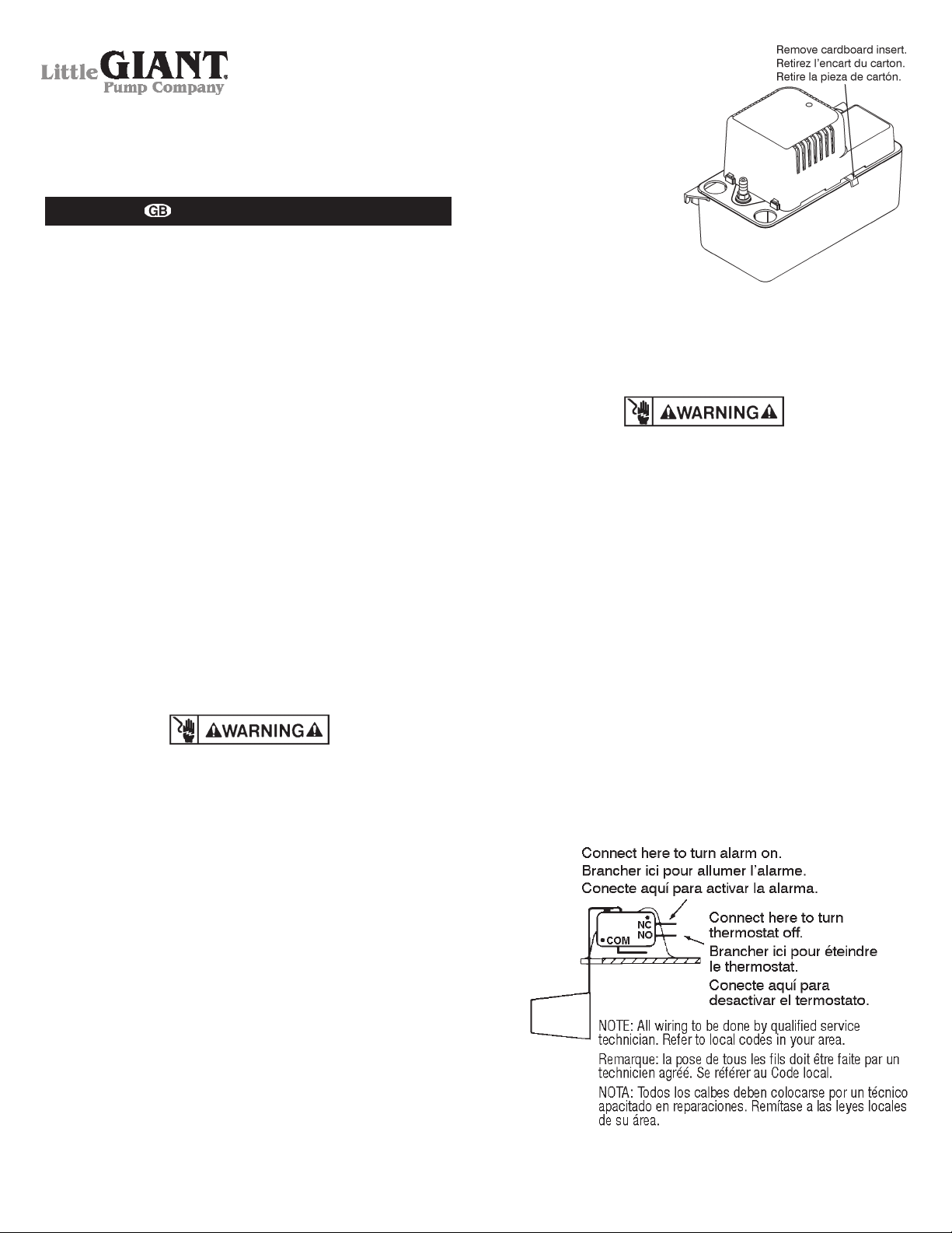
1. Carefully unpack the pump. Remove the cardboard packing
from the motor cover air slots. Carefully slide the packing away
from the pump. This packing is used to prevent switch movement during shipment (Figure 1).
INTRODUCTION
2. Mounting the pump: the
tank has two slots provided to mount the unit.
The slots are located on
the ends of the tank
(Figure 5). The unit should
be mounted either on
the side of the air conditioner unit or nearby wall.
Pump must be level and
the inlet must be below
the coil drain. Conduit
fittings are not compatible with the plastic pump
housing.
3. The pump should not be installed in a manner that will subject
it to splashing or spraying.
4. This pump is not intended for use inside air plenums.
ELECTRICAL CONNECTIONS
1. Shut off electrical power at fuse box before making any connections. All wiring must comply with local codes.
2. Line voltage: Connect power cord to line voltage specified on
motor and nameplate. Power cord must be connected to a
constant source of power (not a fan or other device that runs
intermittently). If power cord does not have a plug, wiring is as
follows: green (or green/yellow)—ground. Black (or brown)—
line. White (or blue)—neutral.
3. Safety switch: The safety overflow switch should be connected
to a class II low voltage circuit. To control a thermostatic circuit
the COM and NO connections from the safety switch are to be
wired in series with the low voltage thermostat circuit to shut
down the heating/AC circuit. The COM and NC switch contacts
may be used to actuate a low voltage alarm circuit (connected
in series) if the heating/cooling system can not be disrupted.
The safety switch comes from the factory with leads connected
to the COM and NO switch terminals. Typical hook-up of “NC”
circuits would be (Figures 2 & 3).
4. If fused plug is used on 230V units, a 1.0 amp fuse is recommended.
1
Little Giant Pump Company
P. O. Box 12010
Oklahoma City, OK 73157-2010
405.947.2511 • Fax: 405.947.8720
www.LittleGiant.com
customerservice@lgpc.com
VCMA-10,VCMA-15,
VCMA-20, CURP-20ULS
Série VCMA-10 VCMA-15
VCMA-20 et CURP-20ULS
Serie VCMA-10 VCMA-15
VCMA-20 y CURP-20ULS
Figure 1.
Figure 2.
Page 2

2
PIPING
1. Run flexible tubing or pipe from evaporator drain into one of
the three pump inlets. Be sure inlet piping is sloped downward
to allow gravity flow (Figure 4). Extend the inlet piping into the
tank from 1 to 3 inches to ensure that it will not interfere with
proper float operation. Be sure that the inlet piping is cut at an
angle where it enters the tank.
2. The outlet piping should be flexible tubing secured with a hose
clamp (not provided) or pipe (3/8 inch I.D. maximum to prevent
excessive flow back to unit). From condensate unit, extend
discharge piping straight up as high as necessary. Do not
extend this line above the head/GPH of the particular model
being installed. From this high point, slope discharge line down
slightly to a point above drain area; then turn down and extend
to a point below or approximately level with the bottom of the
condensate unit. This will give a siphoning effect which will
improve efficiency of the condensate unit and will, in most
cases, eliminate the need for a check valve (Figure 5). If it is
not possible to slope discharge line down, make an inverted
“U” trap directly above the pump at the highest point.
SERVICE INSTRUCTIONS
1. Make certain that the unit is disconnected from the power
source before attempting to service or remove any component!
2. Be sure the floats move freely. Clean as necessary (Figure 6).
3. Clean the tank with warm water and mild soap.
4. Check the inlet and outlet piping. Clean as necessary. Be sure
there are no kinks in the line that would inhibit flow.
TESTING
1. Turn on power.
2. Remove motor/tank cover assembly and hold level.
3. Test motor switch by raising motor switch float with finger
(Figure 6). Motor should turn on just before float contacts cover.
4. Test safety switch by raising safety switch float with finger.
Safety switch should activate before float contacts cover.
5. Replace motor/tank cover assembly on tank.
This pump is suitable for gas furnace condensate applications.
Caution must be taken to ensure acidity of condensate does not
increase below the average pH of 3.4 (to prevent localized pocket
of acid that acts like a battery causing pitting) by routinely cleaning
or flushing tank with fresh water.
Votre pompe a condensats Little Giant est concue comme une
unite automatique d’evacuation des condensats. Elle evacue l’eau
condensee egouttant de la volute de l’evaporateur d’un systeme
de climatisation. La pomp est actionee par un mechisme flotteur/
interrupteur lequel entraine le demarrage dela pompe oorsque
environ 2 po 1/4 d’eau s’accumule dans le reservoir. La pompe
s’arrete automatiquement lorsqu’il ne reste plus qu’environ 1 po
1/4 d’eau.
Votre nouvelle pompe Little Giant a été fabriquée avec les meilleurs
matériaux et avec le plus grand soin. Elle a été conçue pour
foncionner bien et longtemps.
Les pompes Little Giant sont soigneusement emballées, et testées
pour assurer une livraison et un fonctionnement sans problèmes.
Lorsque vous recevez votre pompe, examinez-la attentivement
pour vous assurer qu il n y a pas eu de pièce cassée ou endommagée pendant l acheminement. S il y a eu des dégats, prenez-en
note et signalez-le au magasin où vous avez acheté la pompe. Ils
INTRODUCTION
Figure 3.
Figure 4.
Figure 5.
Figure 6.
Page 3
vous aideront pour le remplacement ou la réparation, si nécessaire. Cette pompe est conçue pour pomper de l eau. NE POMPEZ
PAS de produit chimique, de solvant, d eau salée, ou de liquides
épais tels que des huiles ou de la graisse.
BIEN LIRE LES INSTRUCTIONS AVANT D’INSTALLER, DE FAIRE
FONCTIONNER OU D’ENTRETENIR LA POMPE LITTLE GIANT. IL
FAUT CONNAÎTRE L’APPLICATION, LES LIMITESET LES DANGERS
POTENTIELS DE LA POMPE. PROTÉGEZ-VOUS ET LES AUTRES
EN RESPECTANT TOUTES LES NORMES DE SÉCURITÉ. LE
NON-RESPECT DES INSTRUCTIONS PEUT CAUSER DES
ATTEINTES AUX PERSONNES OU À LA PROPRIÉTÉ! GARDER
LE PRÉSENT DOCUMENT POUR RÉFÉRENCE ULTÉRIEURE.
L´INSTALLATION ET LES BRANCHEMENTS DOIVENT ÊTRE
EFFECTUÉS PAR DES PROFESSIONNELS.
DIRECTIVES DE SECURITE
NE PAS UTILISER POUR POMPER DES LIQUIDES EXPLOSIFS
OU INFLAMMABLES (ESSENCE, HUILE, KÉROSÈNE, ETC.) NE
PAS UTILISER DANS UN ENVIRONNEMENT PROPICE AUX
EXPLOSIONS. UTILISER AVEC DES LIQUIDES COMPATIBLES
AVEC LES MATÉRIAUX DE LA POMPE.
NE PAS MANIPULER LA PUMPE LES MAINS HUMIDES, LES
PIEDS POSES SURE UNE SURFACE MOUILLEE OU HUMIDE,
OU LES PIEDS DANS L’EAU.
VOTRE POMPE VIENT AVEC UN FIL DE MISE A LA TERRE ET/OU
UNE PRISE A TROIS BRANCHES. AFIN DE RÉDUIRE LE
RUSQUE DE CHOC ÉLECTRIQUE, S’ASSURER QUE LA POMPE
EST BRANCHÉE A UNE PRISE CORRECTEMENT MISE A LA
TERRE.
L’UTILISATION D’UN OU DE PLUSIEURS SYSTÈMES AUXILIAIRES
ET/OU D’UN SYSTÈME D’ALARME EST RECOMMANDÉE POUR
TOUTE INSTALLATION POTENTIELLEMENT DANGEREUSE (FUITE
OU DÉFECTUOSITÉ CAUSÉES PAR UNE COUPURE DE COURANT,
UN BLOCAGE DU CIRCUIT DE REFOULEMENT OU POUR TOUTE
AUTRE RAISON) POUR LES PERSONNES OU LA PROPRIËTË.
IMMOBILISER LA POMPE ET LES TUYAUX LORS DE L’INSTALLATION ET DE L’UTILISATION AFIN D’ËVITER TOUT RISQUE DE
DOMMAGES AUX TUYAUX. À LA POMPE AUX ROULEMENTS À
BILLE DU MOTEUR, ETC.
INSTALLATION
1. Déballer la pompe avec précaution en faisant gliser l’emballage. Enlever l’emballage de carton des fetes d’aération qui se
trouvent sur le courvercle du moteur. Cet emballage est
destiné à éviter le mouvement des commutateurs pendant le
transport (Figure 1).
2. Montage-Deux fentes situées à l’extrémité du couvercle de
réservoir, permettent le montage. Celui-ci doit être fait prés d’un
climatiseur ou d’un mur (Figure 5). La pompe doit étre à niveau
et l’arrivée doit se trouver sous le serpentin d’écoulement. Son
carter en plastique n’est pas compatible avec la tuyauterie.
3. Éviter d’installer la pompe où elle pourrait être claboussée ou
arrosée.
4. Cette pompe n’a pas été conçue pour l’intérieur de chambres
de répartition d’air.
CONNEXIONS ELECTRIQUES
1. Avant de faire les connexions, couper le courant électrique à
fusibles et s’assurer que tous les fils sont conformes au Code
local de l’électricité.
2. Ligne de tension : Le câble électrique doit être connecté à la
ligne de tension comme spécifié sur le moteur et sur la plaque
de constructeur. La connexion doit être faite à une source constante et non à une source intermittente comme un ventilateur.
Si le câble électrique n’est pas équipé d’une prise, les fils se
présentent de la façon suivante: vert (ou vert et jaune) à la
terre—noir (ou marron) ligne de tension—blanc (ou bleu)-neutre.
3. Disjoncteur : Le disjoncteur de débordement doit être connecté
à un circuit à basse tension de catégorie II. Pour commander
un circuit thermostatique, les connexions COM et NO de
l’interrupteur de sécurité doivent être branchées en série avec
le circuit basse tension du thermostat; il est alors possible de
couper le système de chauffage/climatisation. Si une telle
coupure n’est pas désirée, les contacts COM and NO peuvent
aussi être utilisés pour activer une alarme de faible tension
(branchée en série). L’interrupteur de sécurité a été réglé en
usine avec des fils raccordés aux bornes COM et NO.
L’assemblage typique de circuits ‘NC’ serait (Figures 2 & 3).
4. Si une prise avec fusible est utilisée sous une tension de 230
V, l’utilisation d’un fusible de 1 ampère est recommandée.
TUYAUTERIE
1. Courant flexible tubage ou pipe dès evaporator drain into 1 de
la 3 pompe inlets. Pour permettre un bon écoulement, s’assurer
que le tuyau d’admission est bien dirigée vers le bas (Figure 4).
Introduire le tuyau d’entrée de 1 à 3 pouces (de 2,5 à 7,5 cm)
à l’intérieur du réservoir afin de s’assurer qu’il ne nuise pas au
fonctionnement du flotteur. Vérifier que le tuyau d’entrée est
coupé en angle à son entrée dans le réservoir.
2. Le tuyau de sortie, s’il est flexible, doit être fixé avec une pince
à tuyaux (non comprise). S’il est rigide, il ne doit pas dépasser
3/8 po (0,5 cm) de D.I., afin d’éviter un reflux excessif vers la
pompe. Á partir de l’unité d’extraction, étirer verticalement le
tuyau d’écoulement jusqu’à la bonne hauteur. Ne pas l’étirer
au dessus de la tête/GPH du modèle installé. De ce point haut,
incliner légèrement le tuyau d’écoulement vers un point situé
au-dessus de lieu d’écoulement; rabattre et étirer jusqu’à un
point situé en-doussous ou à peu près au même niveau que
le bas du système de condensation ce qui donnera un effet de
siphon qui en augmentera l’efficacité et éliminera pratiquement
l’installation d’une soupape d’arrêt (Figure 5). S’il n’est pas
possible d’incliner le tuyau d’écoulement, faire un branchement en U inversé, à un point situé le plus haut au-dessus de
la pompe.
DIRECTIVES D’ENTRETIEN
1. Votre pompe demandera très peu d’entretien. Si, pour une raison quelconque, elle ne peut pas fonctionner, suivez les
instructions ci- dessous!
2. Veillez à ce que les flotteurs bougent librement. Nettoyez-les
au besoin (Figure 6).
3. Nettoyez le réservoir à l’eau tiède et au savon.
4. Vérifiez la tuyauterie d’alimentation et de sortie. Nettoyez-la au
besoin. Assurez-vous que les tuyaux ne présentent aucun
tortillement pouvant influer sur le débit.
3
Page 4

VÉRIFICATION
1. Mettre la pompe en marche.
2. Enlever le couvercle qui couvre l’ensemble moteur, réservoir
et le supporter de niveau.
3. Tester le commutateur de moteur en levant le commutateur de
moteur du flotteur avec le doigt (Figure 6). Le moteur doit se
mettre en marche avant que le flotteur ne touche le couvercle.
4. Tester la sécurité du commutateur en levant le commutateur
de sécurité de flotteur avec le doigt. Le commutateur de
sécurité doit se mettre en marche avant que le flotteur ne
touche le couvercle.
5. Replacer le couvercle sur l’ensemble.
Cette pompe convient aux applications des condensats de radiateurs á gaz. Certaines précautions doivent être prises pour éviter
que l’acidité du condensat ne descende en dessous du pH moyen
de 3,4 ce qui causerait la formation lacalisée d’une poche d’acidité
qui fonctionnerait comme une batterie et causerait de la corrosion.
Il est recommandé de nettoyer ou de rincer périodiquement le
réservoir à l’eau claire.
Su bomba de condensacion Little Giant esta disenada como una
bomba de remocion de condenscion automatica para remover
agua que gotea de las bobinas evaporantes de una unidad de
aire acondicionado. La bombs esta controlada por un mecanismo
flotador/interruptor que activa la bomba aproximadamente cuando
2-1/4" de agua so junta en el tanque, y se apaga automaticamente
cuando elnnivel del agua baja a aprozimadamente 1-1/4".
La unidad Little Giant que usted ha adquirido posee la más alta
calidad de fabricación y materiales. Ha sido diseñada para brindarle
una larga vida de servicio sin problemas.
Las bombas Little Giant se envasan cuidadosamente, registradas
y probadaspara asegurar la entrega y operación segura. Cuando
usted recibe su bomba,examina lo cuidadosamente para determinar que no hay roto o dañado partes que pueden haber ocurrido
durante el embarque. Si el daño ha ocurrido, hechoanotación y
notificado la firma que usted compró la bomba desde. Ellos
ayudarán usted en el reemplazo o la reparación, si requirió.
LEA DETENIDAMENTE LAS INSTRUCCIONES ANTES DE INTENTAR
INSTALAR OPERAR O DAR MANTENIMIENTO A LA BOMBA
LITTLE GIANT. CONOZCA LAS LIMITACIONES, APLICACIONES Y
LOS PELIGROS POTENCIALES DE LA BOMBA. PROTEJASE A SI
MISMO Y A LOS DEMAS CUMPLIENDO TODAS LAS RECOMENDACIONES DE SEGURIDAD.
¡EL INCUMPLIMIENTO DE LAS INSTRUCCIONES PODRIA RESULTAR
EN LESIONES PERSONALES Y/O DAÑOS MATERIALES! CONSERVE LAS INSTRUCCIONES PARA REFERENCIAS FUTURAS.
LA INSTALACIÓN Y LAS CONEXIONES DEBEN SER HECHAS
POR UNA PERSONA CALIFICADA.
NORMAS DE SEGURIDAD
NO USE LA UNIDAD PARA BOMBEAR LIQUIDOS INFLAMABLES NI
EXPLOSIVOS TALES COMO GASOLINA, FUELOIL, QUEROSENO,
ETC. NO USE LA UNIDAD EN AMBIENTES EXPLOSIVOS. LA
BOMBA SE DEBE USAR CON LIQUIDOS COMPATIBLES CON LOS
MATERIALES DE LOS COMPONENTE DE LA BOMBA.
NO MANIPULE LA BOMBA CON LAS MANOS MOJADAS, NI MIENTRAS
SE ENCUENTRE EN UNA SUPERFICIE MOJADAS, NI MIENTRAS
SE ENCUENTRE EN UNA SUPERFICIE MOJADA O HUIMEDA O
ENTRE EL AQUA.
INTRODUCTION
ESTA BOMBA SE SUMINISTRA CON UN CONDUCTOR A TIERRA
Y/O UN ENCHUFE DE CONEXION DE TIPO DE CONEXION A
TIERRA. PARA REDUCIR EL RIESGO DE DESCARGA ELECTRICA
ASEGURESE DE CONECTAR LA UNIDAD A UN RECEPTACULO
DEL TIPO POLARIZADO Y ADECUADAMENTE CONECTADO A TIERRA.
EN CUALQUIER INSTALACION DONDE PUEDAN OCURRIR DAÑOS
MATERIALES Y/O LESIONES PERSONALES QUE RESULTEN DEL
FUNCIONAMIENTO INADECUADO O DE FUGAS EN LA BOMBA A
CAUSA DE FALLOS EN LA ALIMENTACION ELECTRICA, BLOQUEO
DE LA LINEA DE LA DESCARGA, O CUALQUIER OTRA RAZON, SE
DEBERA USAR UNO O VARIOS SISTEMAS DE RESPALDO Y/O
ALARMAS.
IAPOYE LA BOMBA Y LA TUBERIA DURANTE EL ENSAMBLADO DE
LA UNIDAD Y AL COMPLETAR LA INSTALACION. EL NO HACERLO
ASI PUEDE CAUSAR LA RUPTURA DE LA TUBERIA, EL FALLO DE
LA BOMBA, EL FALLO DE LOS COJINETES DEL MOTOR, ETC.
INSTALACIÓN
1. Desempaque la bomba cuidadosamente. Quite el embalaje
de cartón de los orificios de ventilación de la cubierta del
motor. Retire el embalaje de la bomba, haciéndolo deslizar
cuidadosamente. Este embalaje se usa para evitar el movimiento de los interruptores durante el transporte (Figura 1).
2. Montaje de la bomba: el tanque tiene dos ranuras, destinadas
a montar la unidad. Las ranuras se encuentran situadas en el
extremo de la cubierta del tanque (Figura 5). La unidad deberá
montarse al lado de la unidad del acondicionador de aire o en
una pared cercana a ella. La bomba deberá estar nivelada y la
toma deberá encontrarse debajo de la bobina de drenaje. Los
accesorios de tubo aislador no son compatibles con la caja
plástica de la bomba.
3. La bomba no debería instalarse de tal forma que quede
expuesta a salpicaduras o rociaduras.
4. Esta bomba no está preparada para usar dentro de la cámara
impelente de aire.
CONEXIONES ELECTRICAS
1. Desconecte la corriente eléctrica en la caja de fusibles, antes
de hacer cualquier conexión. El tendido de cables debe
ajustarse totalmente a la legislación local.
2. Voltaje de la línea: conecte el cable eléctrico a una línea del
voltaje especificado en el motor y en la placa del constructor.
El cable eléctrico debe estar conectado a una fuente constante
de electricidad (no un ventilador u otro dispositivo que funcione
de manera intermitente). Si el cable eléctrico carece de enchufe,
los cables son los siguientes: verde (o verde y amarillo)—a
tierra; negro (o marrón)—circuito; blanco (o azul)—neutro.
3. Interruptor de seguridad: el interruptor de seguridad de exceso
sobre la capacidad, debe encontrase conectado a un circuito
de bajo voltaje de la clase II. Para controlar un circuito termostático, las conexiones COM y NO del interruptor de
seguridad tienen que ser conectadas en serie con el circuito
del termostato de bajo voltaje, para que apague el sistema de
calefacción/aire acondicionado. Los contactos COM y NC del
interruptor pueden usarse para activar un circuito de bajo
voltaje de alarma (conectado en serie), si el sistema de calefacción/aire acondicionado no puede ser interrumpido. El
interruptor de seguridad se suministra desde la fábrica con
los cables conectados a los bornes COM y NO del interruptor.
El prototipo de la conexión de los circuitos abiertos, sería
(Figuras 2 & 3).
4
Page 5

4. Si se utiliza un enchufe con fusible en unidades a 230 V, se
recomienda el uso de un fusible de 1,0 amperio.
TUBERIA
1. Corra flexible tubería o pipe desde evaporator alcantarilla into
1 de el 3 bomba inlets. Cerciórese de que la tubería de la toma
se encuentre en declive, para permitir el flujo por gravedad
(Figura 4).
2. La tubería de descarga debe ser una tubería flexible o tubos
de un diámetro interno máximo de 3/18 de pulgada, para evitar
un reflujo excesivo a la unidad. Desde la unidad de agua de
condensación, extienda la tubería directamente hacia arriba, a
la altura que sea necesaria. No tienda esta tubería por encima
de la cabeza/GPH del modelo específico que se esté instalando. Desde esta altura, coloque la tubería de descarga en
declive ligero, hasta un punto por encima del área de drenaje.
Luego, vuélvala hacia abajo y tiéndala hasta un punto que se
encuentre aproximadamente al mismo nivel del fondo de la
unidad de agua de condensación o por debajo de éste. Esto
producirá un efecto de sifón, que incrementará la eficiencia de
la unidad de agua de condensación, y en la mayoría de los
casos eliminará la necesidad de una válvula de retención
(Figura 5). Si no es posible colocar en declive la tubería de
descarga, haga un purgador en forma de “U” invertida, directamente sobre la bomba, en el punto más alto.
INSTRUCCIONES DE SERVICIO
1. ¡Asegurese de que la unidad este desconectada de la fuenta
de alimentacion electrica antes de intentar prestar servicio a la
unidad o quitar cualquier componente de ella!
2. Asegúrese de que el flotador se mueva libremente. Limpie
cuando sea necesario (Figura 6).
3. Limpie el tanque con agua caliente y con un jabón suave.
4. Verifique la tubería de entrada y salida. Limpie cuando sea
necesario. Asegúrese de que no haya torceduras en la línea
que puedan detener el paso del líquido.
COMPROBACION
1. Conecte la electricidad.
2. Quite el conjunto del motor y la cubierta del tanque y consérvelo
nivelado.
3. Pruebe el interruptor del motor, levantando su flotador con el
dedo (Figura 6). El motor deberá activarse, antes de que el
flotador entre en contacto con la cubierta.
4. Pruebe el interruptor de seguridad, levantando su flotador con
el dedo. El interruptor de seguridad deberá activarse, antes de
que el flotador entre en contacto con la cubierta.
5. Vuelva a colocar sobre el tanque el conjunto de la cubierta del
motor y la cubierta del tanque.
La bomba es adecuada para el uso en aguas de condensación de
hornos de gas. Debe tenerse cuidado de verificar que la acidez
del agua de condensación no aumente por debajo del nivel de
acidez promedio de 3,4 (para evitar una bolsa de ácido) que actuaría como una pila, causando una corrosión localizada) limpiando o
enjuagando rutinaria mente el tanque con agua limpia.
5
Figure 7.
Page 6

6
ITEM NO.
REPERE
ARTÍCULO
P/N
DESCRIPTION • DESCRIPTION • DESCRIPCIÓN
(Figure 7)
554481
VCMA-10S
554401
VCMA-15UL
554405
VCMA-15ULS
554415
VCMA15ULST
554411
VCMA 15-ULT
554450
VCMA-20
554421
VCMA-20UL
554451
VCMA-20UL
554425
VCMA-20ULS
554455
VCMA-20ULS
554435
VCMA20ULST
554461
VCMA-20ULST
554431
VCMA-20ULT
554471
VCMA-20S
554472
VCMA-20ST
554473
VCMA-20S
577425
CURP-20ULS
1 154401 Tank, Black, ABS • Réservoir, Noir, ABS • Tanque, Negra, ABS • • • • • • • • • • • • • • • • •
2 154411
Tank, Cover, ABS • Couvercle, Réservoir, ABS • Cubierta Del
Tanque, ABS
• • • • • • • • • • • • • • • • •
3 154491
Volute/Motor Assy. • Ensemble Volute/Moteur • Ensamblaje
Voluta/Motor, 115V, 60Hz
• • • •
3 154492
Volute/Motor Assy. • Ensemble Volute/Moteur • Ensamblaje
Voluta/Motor, 115V, 60Hz
• • • • •
3 154493
Volute/Motor Assy. • Ensemble Volute/Moteur • Ensamblaje
Voluta/Motor, 230V, 50/60Hz
• • • • • • •
3 154494
Volute/Motor Assy. • Ensemble Volute/Moteur • Ensamblaje
Voluta/Motor, 230V, 50Hz
•
4 154421
Motor, Cover, ABS, Natural • Couvercle, Carter De Moteur, ABS,
Naturel • Cubierta, Caja Del Motor, ABS, Natural
• • • • • • • • • • • • • • • • •
5 154715 Check Valve • Soupape D’arrêt • Válvula De Retención • • • • • • • • • • • • • • • • •
6 154452 Float Arm • Bras Du Flotteur • Brazo Del Flotante • • • • • • • • • • • • • • • • •
7 154471
Switch Holder, ABS, Natural • Support De L’interrupteur, ABS,
Naturel • Portador De Interruptor, ABS, Natural
• • • • • • • • • • • • • • • • •
8 951604
Wiring Harness Assy., 115v, 6' With Terminals • Montage
Faisceau De Câbles, 6 Pieds (15 Cm) Avec Bornes • Conjunto
De Colector De Cables, 6 Pies Con Bornes
• • • • • • • • •
8 951606
Wiring Harness Assy., 230v, 6' With Terminals • Montage
Faisceau De Câbles, 6 Pieds (15 Cm) Avec Bornes • Conjunto
De Colector De Cables, 6 Pies Con Bornes
• • • •
8 951089
Wiring Harness Assy., 230v, 6' With Terminals • Montage
Faisceau De Câbles, 6 Pieds (15 Cm) Avec Bornes • Conjunto
De Colector De Cables, 6 Pies Con Bornes
• • •
8 951088
Wiring Harness Assy., 230v, 3M With Terminals Ho5vv-F
• Montage Faisceau De Câbles, 3M (7,5 Cm) Avec Bornes
• Conjunto De Colector De Cables, 3 Metros Con Bornes
•
9 902414
Tapping Screw • Vis Taraudée • Tornillo, Rosca Macho,
8-18 x 5/8"
5 5 5 5 5 5 5 5 5 5 5 5 5 5 5 5 5
10 950337 Switch • Commutateur • Interruptor • • • • • • • • • • • • • • • • •
11 929602
Drain Hole Plug • Bouchon, Orifice D’écoulement • Tapón
Agujero De Desagüe
2 2 2 2 2 2 2 2 2 2 2 2 2 2 2 2 •
12 154455
Float Pivot Pin • Axe De Pivotement Du Flotteur • Pasador De
Pivote De Flotante
• • • • • • • • • • • • • • • • •
13 951941
Lead Wire Assy. • Assemblage Fils Plumbés • Conjunto De Hilos
Conductores
• • • • • • • • • • • • • • • • •
14 154465
Safety Switch Assy. • Montage Interrupteur De Sécurité
• Conjunto De Interruptor De Seguridad
• • • • • • • • • •
15 944302
Tubing (not shown) • Tube (non illustré) • Tuberia, 3/8" x 1/2" x 20'
(no se muestra)
• • • • • •
Page 7

7
LIMITED WARRANTY
Your Little Giant product is guaranteed to be in perfect condition
when it leaves our Factory. It is warranted against defective materials
and workmanship for a period of 12 months (90 day warranty on
Models: 1-AA-OM, GKPK-SC, PP-1, PPS-1, PP-12, PPS-12, PP-230
and Cooler King) from date of purchase by the user. No warranty
on brush wear in Model 35-OM and impeller or cam in Models
PP-1, PP-12, and PP-230.
Any product that should fail for either of the above two reasons
and is still within the warranty period will be repaired or replaced
at the option of Little Giant as the sole remedy of buyer. For our
customers in the CONTINENTAL UNITED STATES: Please return
the defective unit, postage paid, to the factory at 301 North
MacArthur Blvd., Oklahoma City, OK 73127-6616. All defective
product returned under warranty will be fully inspected to determine
the cause of failure before warranty is approved.
For our customers located elsewhere; it is not economical, due to
duties and freight, to return the pump to the factory for inspection.
Please return the defective unit to any authorized distributor or
dealer with a brief written explanation of the problem. If there are
no apparent signs of customer abuse, unit will be repaired or
replaced. If dispute arises over replacement of the pump, the
distributor or dealer is to segregate such items and hold for
inspection by a representative of Little Giant Pump Company or
notify factory with details of the problem for factory disposition and
settlement of warranty claim.
DISCLAIMER: THE FOREGOING WARRANTY IS AN EXCLUSIVE
WARRANTY IN LIEU OF ANY OTHER EXPRESS WARRANTIES.
ANY IMPLIED WARRANTIES (INCLUDING, BUT NOT LIMITED TO
ANY IMPLIED WARRANTY OF MERCHANTABILITY OR FITNESS
FOR A PARTICULAR PURPOSE) TO THE EXTENT EITHER
APPLIES TO A PUMP SHALL BE LIMITED IN DURATION TO THE
PERIODS OF THE EXPRESS WARRANTIES GIVEN ABOVE.
Warranty will be VOID if any of the following conditions are found:
1. Sealed motor housing opened.
2. Product connected to voltage other than indicated on nameplate.
3. Cord cut off to a length less than three feet.
4. Pump allowed to operate dry (fluid supply cut off).
5. Pump used to circulate anything other than water.
6. Product abuse by customer.
Any oral statements about the product made by the seller, the
manufacturer, the representatives or any other parties, do not constitute warranties, shall not be relied upon by the user and are not
part of the contract for sale. Seller’s and manufacturer’s only obligation, and buyer’s only remedy, shall be the replacement and/or
repair by the manufacturer of the product as described above.
NEITHER SELLER NOR THE MANUFACTURER SHALL BE LIABLE
FOR ANY INJURY, LOSS OR DAMAGE, DIRECT, INCIDENTAL OR
CONSEQUENTIAL (INCLUDING, BUT NOT LIMITED TO INCIDENTAL OR CONSEQUENTIAL DAMAGES FOR LOST PROFITS, LOST
SALES, INJURY TO PERSON OR PROPERTY, OR ANY OTHER
INCIDENTAL OR CONSEQUENTIAL LOSS), ARISING OUT OF THE
USE OR THE INABILITY TO USE THE PRODUCT AND THE USER
AGREES THAT NO OTHER REMEDY SHALL BE AVAILABLE TO
IT. Before using, the user shall determine the suitability of the product for the intended use, and user assumes all risk and liability
whatsoever in connection therewith.
Some states and countries do not allow limitations on how long an
implied warranty lasts or the exclusion or limitation of incidental or
consequential damages, so the above limitations or exclusions
may not apply to you. This warranty gives you specific legal rights,
and you may also have other rights which vary from state to state
and country to country.
The National Electric Code (in the USA) and similar codes in other
countries require a Ground Fault Circuit Interrupter (GFCI) to be
installed in the branch circuit supplying fountain equipment rated
above 15 volts. 115 volt GFCI’s (with various cord lengths) are in
stock, and we recommend each pump be used with a GFCI.
GARANTIE LIMITÉE
La présente garantit que votre pompe Little Giant est en parfaite
condition à sa sortie de l’usine. La pompe est garantie contre tout
défaut de matériau ou de fabrication pendant une période de 12
mois (90 jours pour les Modèles: 1-AA-OM, GKPK-SC, PP-1, PPS-1,
PP-12, PPS-12, PP-230 et Cooler King) à partir de la date d’achat
initial. L’usure des balais sur le modèle 35-OM ainsi que les dommages au rotor ou à la came sur les modèles PP-1, PP-12 et PP-230
ne sont pas couverts par la présente garantie.
Tout produit encore garanti qui serait défectueux pour l’une des
deux raisons sus-mentionnées sera réparé ou remplacé à la
discrétion du fabricant. L’acheteur n’aura pas d’autre recours.
Pour nos clients aux ÉTATS-UNIS (territoire continental seulement) :
Veuillez retourner l’article défectueux suffisamment affranchi à
l’usine à l’adresse suivante 301 North MacArthur Blvd., Oklahoma
City, OK 73127-6616. Tous les produits garantis retournés feront
l’objet d’une inspection détaillée afin de déterminer si la défectuosité est couverte par la garantie. Pour les clients à l’extérieur des
États-Unis : étant donné les frais de douane et de transport, il n’est
pas économique de retourner la pompe à l’usine pour inspection.
Expédier la pompe ainsi qu’une brève description du problème à
tout distributeur ou détaillant autorisé. Si elle ne présente aucun signe
apparent d’une mauvaise utilisation, elle sera remplacée ou réparée.
S’il y a conflit sur la nécessité de remplacer la pompe, le distributeur ou le détaillant devra garder celle-ci et, soit la fera inspecter
par un représentant de Little Giant Pump Company, soit avisera
l’usine du problème afin de connaître la décision de celle-ci et le
règlement de la réclamation.
DÉNÉGATION : LA GARANTIE ÉNONCÉE DANS LES PRÉSENTES
EST EXCLUSIVE ET REMPLACE TOUTE AUTRE GARANTIE
EXPRESSE OU IMPLICITE; CELA COMPORTE, MAIS NON
EXCLUSIVEMENT, TOUTE GARANTIE IMPLICITE D’APTITUDE À
LA COMMERCIALISATION OU D’APTITUDE PARTICULIÈRE,
POUVANT S’APPLIQUER À UNE POMPE LITTLE GIANT. DE
PLUS, ELLE NE S’APPLIQUE QUE DURANT LA PÉRIODE DE
COUVERTURE PRÉCISÉE CI-DEVANT.
La présente garantie sera ANNULÉE si :
1. Le boîtier scellé du moteur a été ouvert;
2. Le branchement à une tension autre que celle indiquée sur la
plaque du fabricant a été effectué;
3. Le fil d’alimentation a été coupé à une longueur inférieure à
0,91 m (trois pieds);
4. La pompe a tourné à vide (l’alimentation en liquide a été coupée);
5. La pompe a été utilisée pour faire circuler des liquides autres
que de l’eau;
6. La pompe a été mal utilisée.
Toute déclaration sur la pompe faite oralement par le vendeur, le
fabricant, le représentant ou par toute autre partie ne constitue
pas une garantie et, par conséquent, ne peut servir à l’utilisateur.
De plus, une telle déclaration ne peut, en aucun cas, faire partie du
contrat de vente. L’unique obligation du vendeur et du fabricant, et
l’unique recours de l’acheteur, est le remplacement ou la réparation
de la pompe selon les modalités décrites précédemment. NI LE
VENDEUR NI LE FABRICANT NE PEUVENT ÊTRE TENUS
RESPONSABLES DE TOUTE BLESSURE, TOUTE PERTE, OU TOUT
DOMMAGE DIRECT, INDIRECT OU ACCESSOIRE (INCLUANT,
MAIS NON EXCLUSIVEMENT, LES VENTES OU PROFITS PERDUS,
LES ATTEINTES AUX PERSONNES OU À LA PROPRIÉTÉ OU
Page 8

8
©Copyright 2005 Little Giant Pump Co.
Form 998086 — 12/2005
Little Giant Print Services
TOUTE AUTRE PERTE INDIRECTE OU ACCESSOIRE) RÉSULTANT
DE L’UTILISATION OU DE L’INCAPACITÉ D’UTILISATION DE LA
POMPE, ET L’ACHETEUR CONVIENT QU’IL NE DISPOSE
D’AUCUN AUTRE RECOURS. L’acheteur doit s’assurer que la pompe
convient à l’usage projeté; il assume aussi tout risque et toute
responsabilité relativement à cet usage.
Certaines juridictions ne permettent pas la limitation de la durée
d’une garantie ou l’exclusion ou la limitation de responsabilité pour
des dommages indirects ou accessoires. Par conséquent, il est possible que la limitation ou l’exclusion indiquée précédemment puisse
ne pas être applicable. Cette garantie vous donne des droits particuliers
et peut-être d’autres, dépendamment des juridictions en vigueur.
Le code national de l’électricité et autres codes semblables
d’autres pays exigent l’installation d’un interrupteur avec mise à la
terre (GFI) sur le circuit d’alimentation de la fontaine pour toute
installation dont la tension est supérieure à 15 volts. Nous offrons
de tels interrupteurs (avec différentes longueurs de fil) et nous
recommandons que chaque pompe soit reliée à un interrupteur
de ce type.
GARANTIA LIMITADA
El producto que Little Giant le ofrece está garantizado a estar en
perfectas condiciones al momento de salir de la fábrica. El producto
está garantizado contra materiales y fabricación defectuosa por
un período de 12 meses (una garantía de 90 días para los
Modelos: 1-AA-OM, GKPK-SC, PP-1, PPS-1, PP-12, PPS-12, PP-230
y Cooler King) desde la fecha en la cual fue comprada por el
usuario. No hay garantía contra el gasto del cepillo del Modelo 35OM e impulsor o leva en los Modelos PP-1, PP12 y PP-230.
Cualquier producto que falle por alguna de las dos razones anteriores y que esté dentro del período de garantía será reparado o
reemplazado a opción de Little Giant y éste será el único remedio
del comprador. Para nuestros clientes en los ESTADOS UNIDOS
CONTINENTALES: Por favor, devolver la unidad defectuosa, con
el porte pagado, a la fábrica en 301 North MacArthur Blvd., Oklahoma
City, OK 73127-6616. Todo producto defectuoso devuelto bajo la
garantía será cuidadosamente inspeccionado para determinar la
causa de la falla antes de aprobar la garantía. Para nuestros clientes
ubicados en otros lugares; no es económico devolver la bomba a la
fábrica para que ésta sea inspeccionada, debido a los impuestos y
al flete.
Por favor, devuelva la unidad defectuosa a cualquier distribuidor o
vendedor autorizado con una breve explicación por escrito del
problema. Si no existen señas aparentes de abuso por parte del
cliente, la unidad será reemplazada o reparada. Si se produce
una disputa sobre el reemplazo de la bomba, el distribuidor o
vendedor debe separar los artículos y retenerlos para que sean
inspeccionados por un representante de Little Giant Pump
Company o avisarle a la fábrica de los detalles del problema para
que la fábrica disponga de las acciones necesarias y resuelva el
reclamo de la garantía.
DESAUTORIZACION: LA GARANTIA ANTERIOR ES UNA GARANTIA
EXCLUSIVA EN LUGAR DE CUALQUIER OTRA GARANTIA
EXPRESA. CUALQUIER GARANTIA IMPLICADA (INCLUYENDO
PERO NO LIMITADO A CUALQUIER GARANTIA IMPLICADA DE
COMERCIALIZACION O APTITUD PARA PROPOSITO PARTICULAR) EN LA MEDIDA EN QUE SE PUEDA APLICAR A UNA
BOMBA, QUEDARA LIMITADA EN DURACION A LOS PERIODOS
DE GARANTIAS PROPORCIONADOS ANTERIORMENTE.
La garantía será declarada NULA si se encuentran cualesquiera
de las siguientes condiciones:
1. El alojamiento sellado del motor abierto.
2. El producto conectado a un voltaje que no es el indicado en
la placa principal.
3. El cable cortado a menos de tres pies (0,91 m.).
4. Se permitió que la bomba opere en seco (envío de fluido cortado).
5. La bomba empleada para hacer circular cualquier otra sustancia
que no sea agua.
6. Abuso del producto por parte del cliente.
Cualquier declaración oral acerca del producto hecha por el
vendedor, fabricante, representantes o cualquiera de las partes,
no constituyen garantías, el usuario no debe confiarse de ellas, y
no forman parte del contrato de compra-venta. La única obligación
del vendedor y del fabricante y el único remedio para el comprador,
será la reposición y/o reparación del producto por parte del fabricante bajo las condiciones descritas anteriormente.
NI EL VENDEDOR NI EL FABRICANTE SE HACEN RESPONSABLES DE NINGUNA LESION, PERDIDA O DAÑO, DIRECTO,
INCIDENTAL O CONSECUENTE (INCLUYENDO, PERO SIN LIMITARSE A, DAÑOS INCIDENTALES O CONSECUENTES DEBIDO
A GANANCIAS PERDIDAS, VENTAS PERDIDAS, DAÑOS A PERSONAS O PROPIEDADES O CUALQUIER OTRA PERDIDA INCIDENTAL O CONSECUENTE), QUE RESULTE DEL USO O DE LA
IMPOSIBILIDAD DEL USO DEL PRODUCTO, Y EL COMPRADOR
ACUERDA QUE NO EXISTE OTRO REMEDIO DISPONIBLE PARA
EL. Antes de usar, el usuario debe determinar si el producto se
adapta al uso deseado, y el usuario asume todos los riesgos y
responsabilidades en relación a ello.
Algunos estados y países no permiten limitaciones sobre la
duración de una garantía implícita o la exclusión o limitación de
daños incidentales o consecuentes, de manera que las limitaciones
o exclusiones anteriores podrían no tener aplicación en su caso.
Esta garantía le da derechos legales específicos, y usted podría
disponer también de otros derechos que varían de un estado a
otro y de un país a otro.
El Código Eléctrico Nacional (en los Estados Unidos) y códigos
similares en otros países requieren un Interruptor de circuito de
falla de conexión a tierra (GFCI) para ser instalado en el circuito
secundario que suministra equipo de fuente calibrado por encima
de 15 voltios. En el almacén se encuentran GFCI de 115 voltios
(con varias longitudes de cable), y recomendamos que cada
bomba sea usada con un GFCI.
For Parts or Repair, please contact . . . . . . . . . . . . . . . . . . . . . . . . . . . . . . . . . . . .1.888.572.9933
For Technical Assistance, please contact . . . . . . . . . . . . . . . . . . . . . . . . . . . . . . .1.888.956.0000
Pour des Parties ou la Réparation, entrez s'il vous plaît en contact . . . . . . . . .1.888.572.9933
Pour l'Aide Technique, entrez s'il vous plaît en contact . . . . . . . . . . . . . . . . . . . .1.888.956.0000
Para Partes o la Reparación, por favor póngase en contacto . . . . . . . . . . . . . .1.888.572.9933
Para la Ayuda Técnica, por favor póngase en contacto . . . . . . . . . . . . . . . . . . .1.888.956.0000
www.LittleGiant.com
customerservice@lgpc.com
 Loading...