

Littfinski DatenTechnik (LDT)
Operating Instruction
4-fold decoder for single coil
turnouts
from the Digital-Professional-Series !
1-DEC-DC-F Part-No.: 110412
>> finished module <<
Compatible to the DCC-Format:
Turnouts can also be controlled via loc-addresses
(e.g. Lokmaus 2® and R3®).
For the digital control of:
⇒ up to four LGB turnout drives.
(LGB Part No. EPL 12010)
⇒ up to four PIKO G turnout drives.
(PIKO Part No. 35271)
⇒ up to four KATO UNITRACK, TOMIX and
ROKUHAN turnout drives.
⇒ switching current up to 1 Ampere on each
This product is not a toy! Not suitable for children under 14 years of age! The kit
contains small parts, which should be kept away from children under 3! Improper
use will imply danger of injuring due to sharp edges and tips! Please store this
instruction carefully.
CE Part-No.:
71 32 47
yellow point
Introduction/Safety instruction:
You have purchased the 4-fold turnout decoder 1-DEC-DC for
your model railway a kit or as finished module supplied within
the assortment of Littfinski DatenTechnik (LDT).
We wish you having a good time using this product.
The 1-DEC-DC decoder (receiver device is marked with a
yellow dot) is suitable for the DCC-Format as used by the
systems of Lenz-Digital Plus, Arnold-, Märklin-Digital=,
Intellibox, TWIN-CENTER, Roco-Digital, EasyControl, ECoS,
KeyCom-DC, Digitrax, DiCoStation and Zimo.
The decoder 1-DEC-DC can control the turnouts either via
turnout-addresses or via loc-addresses. Therefore is it
possible to switch the turnouts for example by using the push
buttons F1 to F4 of the Lokmaus 2® or R3®.
The finished module comes with 24 month warranty.
• Please read the following instructions carefully. Warranty will
Connecting the decoder to your digital
model railway layout:
• Attention: Before starting any installation switch off all
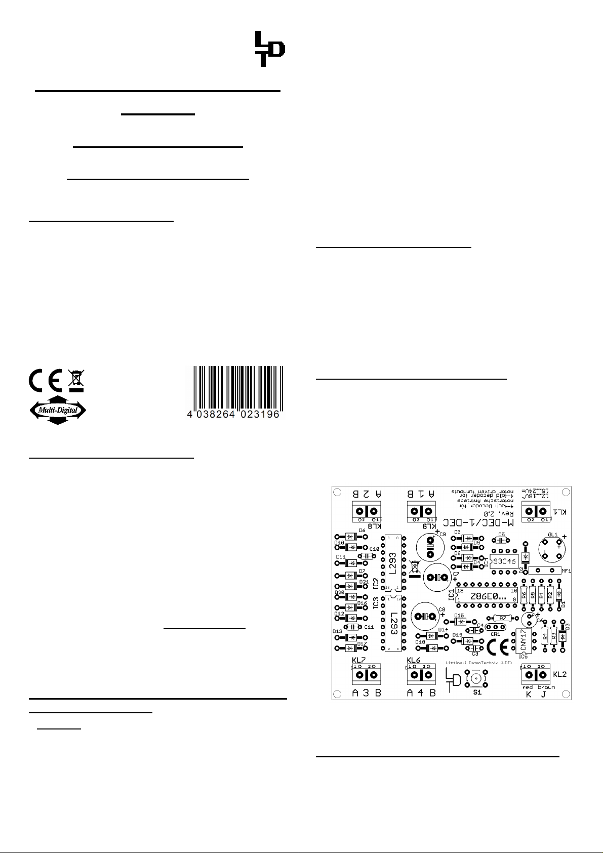
The decoder receives the digital information via the clamp
KL2. Connect the clamp with a rail or even better connect the
clamp directly to the command station or to a booster
assuring the supply of digital information free from any
interference.
output.
expire due to damages caused by disregarding the operating
instructions. LDT will also not be liable for any consequential
damages caused by improper use or installation.
power supply to the digital layout by pushing the stop
button or disconnect all main supply to the transformers.
Pay attention to the mark at clamp KL2. The color markings
'Black/Schwarz' and 'Red/Rot' next to the clamp are used for
Arnold-Digital (old) and Märklin-Digital= .
The Lenz Digital plus systems uses the letters 'J' and 'K'.
If you use the decoder with Intellibox you have to connect the
digital wires to 'red/rot' and 'brown/braun'.
The correct connection for LGB is schwarz/K/rot (black/K/red)
= LGB BLUE and rot/J/braun (red/J/brown) = LGB RED.
The decoder receives the power supply via the two poles
clamp KL1. Voltage in the range of 12…18V~ is acceptable
(alternate current output of a model railway transformer) or
15...24 V= (direct voltage from a switched mode mains power
supply).
If you do not want to supply power to the decoder 1-DEC-DC
from an external transformer you can connect the clamp
KL1 to KL2 with two wires. In this case the decoder will get the
power supply complete from the digital system.
Connecting turnout drives:
The Decoder 1-DEC-DC is suitable for digital switching of
single coil turnout drives. Those drives contain two
connection wires. This wires shall be directly connected with
one of the output clamps KL6 to KL9.
ROKUHAN turnout drives shall be supplied with a voltage of
10 to 12 Volt only. For reducing the voltage is it required to
apply two 9,1Volt Z-Diodes on each output . The connection
sample 1275 to be downloaded from our internet site from the
section “Sample Connection” will show the wiring.
Programming the decoder address:
To program the decoder address a turnout drive has to be
connected to the output 1 (clamp KL9) of the decoder.
• Switch on the power supply of your model rail way.
• Press the programming key S1. Do not touch the
integrated circuits of the pc-board because any electrostatic
discharge can destroy the IC`s.
• The turnout drive connected to output 1 will now move every
1,5 seconds. This indicates that the decoder is in the
programming mode.
Switching turnouts via turnout addresses:
• Press now one key of a key group to be assigned to the
decoder. For programming the decoder address you can
also release a turnout switch signal via a personal computer
over the model railway software.

Remarks: The decoder addresses for magnetic accessories
are combined in groups of four. The addresses 1 to 4 build
the first group. The addresses 5 to 8 build the second group
etc. Each 1-DEC-DC decoder can be assigned to any of
these groups. Which turnout of a group will be activated for
the addressing does not matter.
• If the decoder has recognized the assignment correctly the
connected turnout will move a little faster. Afterwards the
movement slows down to the initial 1,5 seconds again.
In case the decoder will not recognize the address it could
be that the two digital information connections (clamp 2) are
wrong way connected. For testing this, switch the power
supply off, exchange the connection on KL2 and start
addressing again.
• Leave the programming mode by pressing the programming
key S1 again. The decoder address is now permanently
stored but it can be changed at any time by repeating the
programming as described above.
• If you press now the first key of the programmed group of
keys or you send a switch signal for this turnout from a PC
the addressed turnout drive should move into the called
direction (round or straight) until end stop. In case the
movement goes in the wrong direction please exchange the
turnout connection.
Switching turnouts via loc-addresses
(Lokmaus 2® or R3®):
The decoder 1-DEC-DC can also control turnouts via locaddresses. For example with the functional keys F1 to F4 of
the Lokmaus 2® or R3®.
The turnout connected to output 1 will be switched with the
functional key F1 and the turnout connected to output 2 with
key F2 etc.
Each pressing of a functional key will release a movement of
the respective turnout from turning to straight or vice versa.
To program the loc-addresses a turnout drive has to be
connected to the output 1 (clamp KL9) of the decoder.
• Switch on the power supply of your model railway.
• Adjust the speed of all connected speed controller
respectively all lokmauses to zero (center position of the
adjusting dial).
• Press the programming key S1. Do not touch the
integrated circuits of the pc-board because any electrostatic
discharge can destroy the IC`s.
• The turnout drive connected to output 1 will now move every
1,5 seconds. This indicates that the decoder is in the
programming mode.
• Now adjust the required address on one Lokmaus and turn
the speed control dial away from the center position. If the
decoder has recognized the assignment correctly the
connected turnout will move a little faster. The decoder
1-DEC-DC will accept loc-addresses between 1 and 99.
• Adjust the speed control to zero again. The movement of
the connected turnout will slow down to the initial 1,5
seconds.
• Leave the programming mode by pressing the
programming key S1 again.
• If you press the functional key F1 the turnout connected
to output 1 will be switched over by each key stroke. In
case some further turnouts are connected to output 2 to 4 of
the decoder 1-DEC-DC this turnouts will be switched with
the functional keys F2 to F4 with each respective key stroke.
Attention:
• Each of the 4 decoder outputs can switch 1 Ampere max.
For securing the decoder components and the connected
turnout drives the decoder 1-DEC-DC includes an
overload fuse. This is an automatic fuse which will switch
back to normal operation with a few seconds delay as soon
as the current load will be below the maximum value.
Accessory:
For the assembly of the 1-DEC-DC below your layout base
plate is our assembly set MON-Set recommended. For the
ready assembled kits and the finished modules from version 2.0
we offer a suitable case under the order code LDT-01 a suitable
case with the dimension of 93x80x32mm within our program.
If you require for an outdoor application a suitable splash-
water protected case for the 4-fold turnout decoder 1-DECDC from version 2 we can offer you a suitable case of the
dimension of 125x85x55mm under the order coder G-2-DEC.
You will receive this case together with a splash-water
protected cable inlet.
Trouble shooting:
What to do if something is not working as described above?
If you have purchased the decoder as a kit, please check
carefully all parts and soldered joints.
Here some possible functional errors and possible solutions:
1. During programming of the decoder addresses the turnout
moves within 1,5 seconds, but does not confirm the
programming with faster movement by pressing any key.
• Change cable connections at KL2.
• Interfered digital information at KL2 respectively larger
lost of voltage at the tracks! Connect the decoder directly
with cables to the digital control unit or to the booster
instead to the tracks.
• For kits: Is IC5 correct inserted into the socket? Has
resistor R6 actually 220kOhm or has this resistor been
mixed-up with the 18kOhm resistor R5?
2. The programming of the decoder address functions as
described, nevertheless the connected consumers can not be
activated.
• Interfered digital information on KL2 respectively larger
lost of voltage at the tracks result to unsafe data transfer!
Connect the decoder directly with cables to the command
station or the booster.
• For kits: Is IC4 correct inserted into the socket?
Made in Europe by
Littfinski DatenTechnik (LDT)
Kleiner Ring 9
D-25492 Heist/Germany
Phone: 0049 4122 / 977 381
Fax: 0049 4122 / 977 382
Internet: http://www.ldt-infocenter.com
Arnold, Digitrax, Lenz, LGB, Märklin, and Roco are registered trade marks.
Subject to technical changes and errors. 12/2013 by LDT
 Loading...