

Littelfuse ZA Series Catalog Page

Varistor Products
Radial Lead Varistors > ZA Series
RoHS
ZA Varistor Series
Agency Approvals
Agency Agency File Number
E135010, (+ E320116 for selected parts)
116895
42201-006
Description
The ZA Series of transient voltage surge suppressors
are radial leaded varistors (MOVs) designed for
use in the protection of low and medium-voltage
circuits and systems. Typical applications include
motor control, telecom, automotive systems,
solenoid, and power supply circuits to protect circuit
board components and maintain data integrity.
These devices are available in five model sizes:
5mm, 7mm, 10mm, 14mm and 20mm, and feature
a wide V
voltage range of 5.5V to 615V.
DC
See ZA Series Device Ratings and Specifications
Table for part number and brand information.
Features
t -FBEoGSFF)BMPHFO
Free and R
oHS
compliant
t 8JEFPQFSBUJOHWPMUBHF
range V
M(AC)RMS
4V to 460V
t %$WPMUBHFSBUJOHT
5.5V to 615V
t /PEFSBUJOHVQUP
85ºC ambient
t NPEFMTJ[FT
available: 5, 7, 10,
14, and 20mm
t 3BEJBMMFBEQBDLBHFGPS
hard-wired or printed
circuit board designs
t "WBJMBCMFJOUBQFBOE
reel or bulk pack
t 4UBOEBSEMFBE
form options
ZA Series
Absolute Maximum Ratings
t'PSSBUJOHTPGJOEJWJEVBMNFNCFSTPGBTFSJFTTFF%FWJDF3BUJOHTBOE4QFDJmDBUJPOTDIBSU
Continuous ZA Series Units
Steady State Applied Voltage:
AC Voltage Range (V
DC Voltage Range (V
Transients:
Peak Pulse Current (I
Single Pulse Energy Range (Note 1)
Operating Ambient Temperature Range (T
Storage Temperature Range (T
Temperature Coefficient (a
Hi-Pot Encapsulation (COATING Isolation Voltage Capability)
(Dielectric must withstand indicated DC voltage for one minute per MIL–STD–202, Method 301)
COATING Insulation Resistance 1000 MΩ
)
TM
For 8/20μs Current Wave (See Figure 2) 50 to 6500 A
For 10/1000μs Current
) -55 to +125 ºC
STG
V
) of Clamping Voltage (VC) at Specified Test Current <0.01 %/ºC
CAUTION: Stresses above those listed in "Absolute Maximum Ratings" may cause permanent damage to the device. This is a stress only
rating and operation of the device at these or any other conditions above those indicated in the operational sections of this specification is
not implied.
) 4 to 460 V
M(AC)RMS
) 5.5 to 615 V
M(DC)
Wave (W
) -55 to +85 ºC
A
) 0.1 to 52 J
TM
2500 V
©2011 Littelfuse, Inc.
Specifications are subject to change without notice.
Please refer to www.littelfuse.com/series/za.html for current information.
Revision: November 13, 2011
ZA Varistor Series
Varistor Products
Radial Lead Varistors > ZA Series
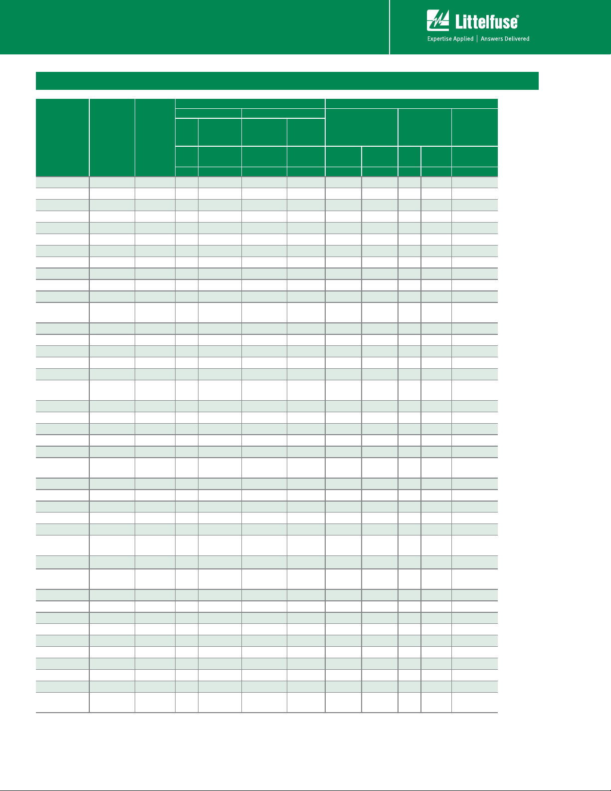
ZA Series Ratings & Specifications
Maximum Rating (85°C) Specifications (25°C)
Part
Number
Branding
Model
Size
Disc Dia.
(mm)
Continuous Transient
DC
M(DC)
Energy 10
x 1000μs
WTM I
V
RMS
V
M(AC)
V
V
Peak
Current
8 x 20μs
Varistor Voltage at
DC Test Current
V
NOM
TM
Min
1mA
V
Max
(V) (V) (J) (A) (V) (V) (V) (A) (pF)
V8ZA05P PZ08 5 4 5.5 0.1 50 6 11 30 1 2000
V8ZA1P P08Z1
7 4 5.5 0.4 100 6 11 22 2.5 4190
V8ZA2P P08Z2 10 4 5.5 0.8 250 6 11 20 5 7000
V12ZA05P PZ12 5 6 8 0.14 50 9 16 37 1 1700
V12ZA1P P12Z1 7 6 8 0.6 100 9 16 34 2.5
V12ZA2P P12Z2 10 6 8 1.2 250 9 16 30 5 6100
V18ZA05P PZ18 5 10 14 0.17 100 14.4 21.6 36 1 1400
V18ZA1P P18Z1 7 10 14 0.8 250 14.4 21.6 36 2.5 2700
V18ZA2P P18Z2 10 10 14 1.5 500 14.4 21.6 36 5 5300
V18ZA3P P18Z3 14 10 14 3.5 1000 14.4 21.6 36 10 18870
V18ZA20P P18Z20 20 10 14 10 2000 14.4 21.6 37 20 22000
V18ZA40P P18Z40 20 10 14
80
(Note2)
2000
14.4
(Note 3)
21.6 37 20 22000
V22ZA05P PZ22 5 14 18 0.2 100 18.7 26 43 1 1220
V22ZA1P P22Z1 7 14 18 0.9 250 18.7 26 43 2.5 2375
V22ZA2P P22Z2 10 14 18 2 500 18.7 26 43 5 4500
V22ZA3P P22Z3 14 14 18 4 1000 18.7 26 43
V24ZA20P P24Z20 20 14 18 12 2000 18.7 26 43 20 18000
V24ZA50P P24Z50 20 14
18
(Note 4)
100
(Note 2)
2000
19.2
(Note 3)
26 43 20 18000
V27ZA05P PZ27 5 17 22 0.25 100 23 31.1 53 1 920
V27ZA1P P27Z1 7 17 22 1 250 23 31.1 53 2.5 1875
V27ZA2P P27Z2 10 17 22 2.5 500 23 31.1 53 5 3850
V27ZA4P P27Z4 14 17 22 5 1000 23 31.1 53 10 11480
V27ZA20P P27Z20 20 17 22 14 2000 23 31.1 53 20 13000
V27ZA60P P27Z60 20 17 22 120
(Note 2) 2000
23
(Note 3)
31.1 50 20 13000
V33ZA05P PZ33 5 20 26 0.3 100 29.5 38 65 1 790
V33ZA1P P33Z1 7 20 26 1.2 250 29.5 36.5 65 2.5 1620
V33ZA2P P33Z2 10 20 26 3
500 29.5 36.5 65 5 3495
V33ZA5P P33Z5 14 20 26 6 1000 29.5 36.5 65 10 9290
V33ZA20P P33Z20 20 20 26 18 2000 29.5 36.5 65 20 13000
V33ZA70P P33Z70 20 21 27
150
(Note 2)
2000
29.5
(Note 3)
36.5 58 20 13000
V36ZA20P P36Z20 20 23 28 20 2000 32 40 70 20 12000
V36ZA80P P36Z80 20 23 31
160
(Note 2)
2000
32
(Note 3)
40 63 20 12000
V39ZA05P PZ39 5 25 31 0.3 100 35 46 79 1 675
V39ZA1P P39Z1 7 25 31 1.2 250 35 43 79 2.5 1350
V39ZA3P P39Z3 10 25 31 3 500 35 43 76 5 3100
V39ZA6P P39Z6 14 25 31 7.2 1000 35 43 76 10 7000
V39ZA20P P39Z20 20 25 31 20 2000 35 43 76 20 12000
V47ZA05P PZ47 5 30
38 0.4 100 42 55 93 1 585
V47ZA1P P47Z1 7 30 38 1.8 250 42 52 93 2.5 1245
V47ZA3P P47Z3 10 30 38 4.5 500 42 52 93 5 2590
V47ZA7P P47Z7 14 30 38 8.8 1000 42 52 93 10 6270
V47ZA20P P47Z20 20 30
38
(Note 6)23(Note 7)
2000 42 52 93 20 11000
NOM
Maximum
Clamping
Voltage
8 x 20μs
IPK C
V
C
10 14730
Typical
Capaci-
tance
f = 1MHz
3350
ZA Varistor Series
Revision: November 13, 2011
©2011 Littelfuse, Inc.
Please refer to www.littelfuse.com/series/za.html for current information.
Specifications are subject to change without notice.

Varistor Products
Radial Lead Varistors > ZA Series
ZA Series Ratings & Specifications (Continued...)
Maximum Rating (85°C) Specifications (25°C)
Part
Number
Branding
Model
Size
Disc Dia.
(mm)
Continuous Transient
V
RMS
V
M(AC)VM(DC)
V
DC
Energy 10
x 1000μs
WTM I
Peak
Current
8 x 20μs
Varistor Voltage at
DC Test Current
V
TM
Min
NOM
1mA
V
Max
(V) (V) (J) (A) (V) (V) (V) (A) (pF)
V56ZA05P PZ56 5 35 45 0.5 100 50 66 110 1 500
V56ZA2P P56Z2 7 35 45 2.3 250 50 62 110 2.5 1035
V56ZA3P P56Z3 10 35 45 5.5 500 50 62 110 5 2150
V56ZA8P P56Z8 14 35 45 10 1000 50 62 110 10 4840
V56ZA20P P56Z20 20 35 45 30 2000 50 62 110 20
V68ZA05P PZ68 5 40 56 0.6 100 61 80 135 1 400
V68ZA2P P68Z2 7 40 56 3 250 61 75 135 2.5 910
V68ZA3P P68Z3 10 40 56 6.5 500 61 75 135 5 1850
V68ZA10P P68Z10 14 40 56 13 1000 61 75 135 10 3870
V68ZA20P P68Z20 20 40 56 33 2000 61 75 135 20 9000
V82ZA05P PZ82 5 50 68 2 400 73 97 135 5 355
V82ZA2P P82Z2 7 50 68 4 1200 73 91 135 10 700
V82ZA4P P82Z4 10 50 68 8 2500 73 91 135 25 1485
V82ZA12P P82Z12 14 50 68 15 4500 73 91 145 50 3380
V82ZA20P P82Z20 20 50 68 25 6500 73 91 145 100 7000
V100ZA05P PZ100 5 60 81 2.5 400 90 117 165 5 310
V100ZA3P
P100Z 7 60 81 5 1200 90 110 165 10 600
V100ZA4P P100Z4 10 60 81 10 2500 90 110 165 25 1200
V100ZA15P P100Z15 14 60 81 20 4500 90 110 175 50 2900
V100ZA20P P100Z20 20 60 81 30 6500 90 110 175 100 6500
V120ZA05P PZ120 5 75 102 3 400 108 138 205 5 250
V120ZA1P P120Z 7 75 102 6 1200 108 132 205 10 515
V120ZA4P P120Z4 10 75 102 12 2500 108 132 200 25 1100
V120ZA6P P120Z6 14 75 102 22 4500 108 132 210 50 2450
V120ZA20P P120Z20 20 75 102 33 6500 108 132 210 100 5000
V150ZA05P PZ150 5 92 127 4 400 135 173 250 5 190
V150ZA1P PZ051 7 95 127 8 1200 135 165 250 10 460
V150ZA4P P150Z4 10
95 127 15 2500 135 165 250 25 860
V150ZA8P P150Z8 14 95 127 20 4500 135 165 250 50 1910
V150ZA20P P150Z20 20 95 127 45 6500 135 165 250 100 3500
V180ZA05P PZ180 5 110 153 5 400 162 207 295 5 100
V180ZA1P P180Z 7 115 153 10 1200 162 198 300 10 320
V180ZA5P P180Z5 10 115 153 18 2500 162 198 300 25 465
V180ZA10P P180Z10 14 115 153 35 4500 162 198 300 50 1190
V180ZA20P P180Z20 20 115 153 52 6500 162 198 300 100 2400
V205ZA05P PZ205 5 130 170 5.5 400 184 226 340 5 100
V220ZA05P PZ220 5 140 180 6 400 198 253 360 5 95
†
V240ZA05P PZ240 5 150 200 7 400 216 264 395 5 90
†
V270ZA05P PZ270 5 175 225 7.5 400 243 311 455 5 75
†
V330ZA05P PZ330 5 210 275 9 400 297 380 540 5 70
†
V360ZA05P PZ360 5 230 300 9.5 400 324 396 595 5 60
†
V390ZA05P PZ390 5 250 330 10 400 351 449 650 5 80
†
V430ZA05P PZ430 5 275 369 11 400 387 495 710 5 75
†
V470ZA05P PZ470 5 300 385 12 400 420 517 775 5 70
†
V620ZA05P PZ620 5 385 505 13 400 558 682 1025 5 45
†
V680ZA05P PZ680 5 420 560 14 400 610 748 1120 5 40
†
V715ZA05P PZ715 5 440 585 15.5 400 643 787 1180 5 35
†
V750ZA05P PZ750 5 460 615 17 400 675 825 1240 5 30
Note:
1. Average power dissipation of transients not to exceed 0.2W, 0.25W, 0.4W, 0.6W or 1W for model sizes 5mm, 7mm, 10mm, 14mm and 20mm, respectively.
2. Energy rating for impulse duration of 30ms minimum to one half of peak current (auto Load Dump).
3. 10mA DC test current.
4. Also rated to withstand 24V for 5 minutes.
5. Higher voltages available, contact Littelfuse.
6. Also rated to withstand 48V for 5 minutes.
7. Energy rating for impulse duration of 30ms minimum to one half of peak current (Auto Load Dump): 100J
† Also Recognized to UL 1449, Transient Voltage Surge Suppressors File E320116
NOM
Maximum
Clamping
Voltage
8 x 20μs
IPK C
V
C
Typical
Capaci-
tance
f = 1MHz
10000
ZA Series
©2011 Littelfuse, Inc.
Specifications are subject to change without notice.
Please refer to www.littelfuse.com/series/za.html for current information.
Revision: November 13, 2011
ZA Varistor Series
Varistor Products
Radial Lead Varistors > ZA Series
Phenolic Coating Option -- ZA Series Varistors for Hi-Temperature Operating Conditions:
t 1IFOPMJDDPBUFE;"4FSJFTEFWJDFTBSFBWBJMBCMFXJUIJNQSPWFENBYJNVNPQFSBUJOHUFNQFSBUVSFPG
t 5IFTFEFWJDFTBMTPIBWFJNQSPWFEUFNQFSBUVSFDZDMJOHQFSGPSNBODFDBQBCJMJUZ
t 3BUJOHTBOETQFDJmDBUJPOTBSFBTQFSTUBOEBSE;"4FSJFTFYDFQU)Jo1PU
Encapsulation (Isolation Voltage Capability) = 500V
t 5PPSEFSBEEh9hUPQBSUOVNCFSFH7;"19
t 5IFTFEFWJDFTBSFOPU6-$4"7%&PS$&$$DFSUJmFE
t $POUBDUGBDUPSZGPSGVSUIFSEFUBJMT
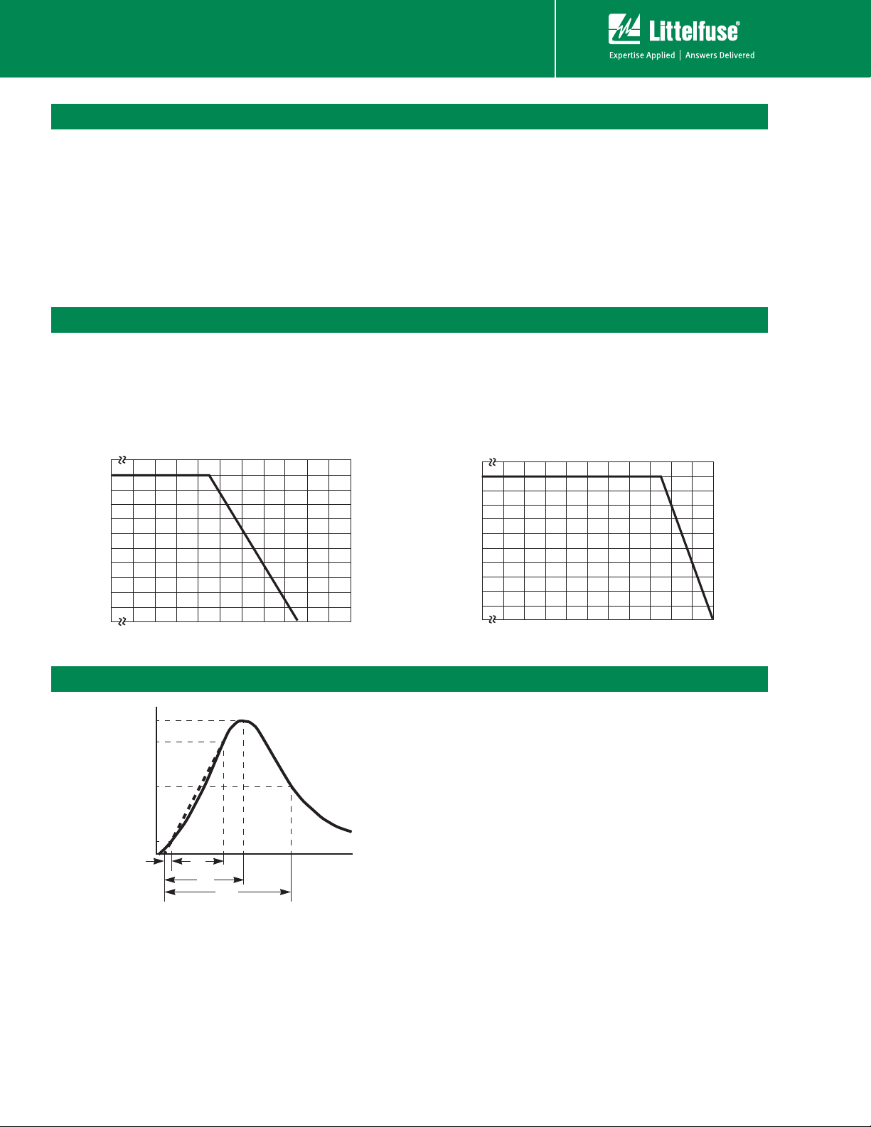
Current Energy and Power Dissipation Ratings
Should transients occur in rapid succession, the average
power dissipation is the energy (watt-seconds) per pulse
times the number of pulses per second. The power so
developed must be within the specifications shown on the
Device Ratings and Specifications Table for the specific
Figure 1A - Power Derating for Epoxy Coated
100
90
80
70
60
50
40
30
20
PERCENT OF RATED VALUE
10
0
-55 50 60 70 80 90 100 110 120 130 140 150
AMBIENT TEMPERATURE (
o
C)
device. The operating values of a MOV need to be derated
at high temperatures as shown above. Because varistors
only dissipate a relatively small amount of average power
they are not suitable for repetitive applications that involve
substantial amounts of average power dissipation.
Figure 1B - Power Derating for Pholenic Coated
100
90
80
70
60
50
40
30
20
PERCENT OF RATED VALUE
10
0
-55 50 60 70 80 90 100 110 120 130 140 150
AMBIENT TEMPERATURE (
o
¡$
C)
Peak Pulse Current Test Waveform
100
90
50
PERCENT OF PEAK VALUE
10
Figure 2
ZA Varistor Series
O
1
T
T
1
T
2
TIME
01 = Virtual Origin of Wave
T = Time from 10% to 90% of Peak
T1 = Rise Time = 1.25 x T
T2 = Decay Time
Example - For an 8/20 μs Current Waveform:
8μs = T1 = Rise Time
20μs = T2 = Decay Time
Revision: November 13, 2011
Please refer to www.littelfuse.com/series/za.html for current information.
©2011 Littelfuse, Inc.
Specifications are subject to change without notice.
3000
600
3
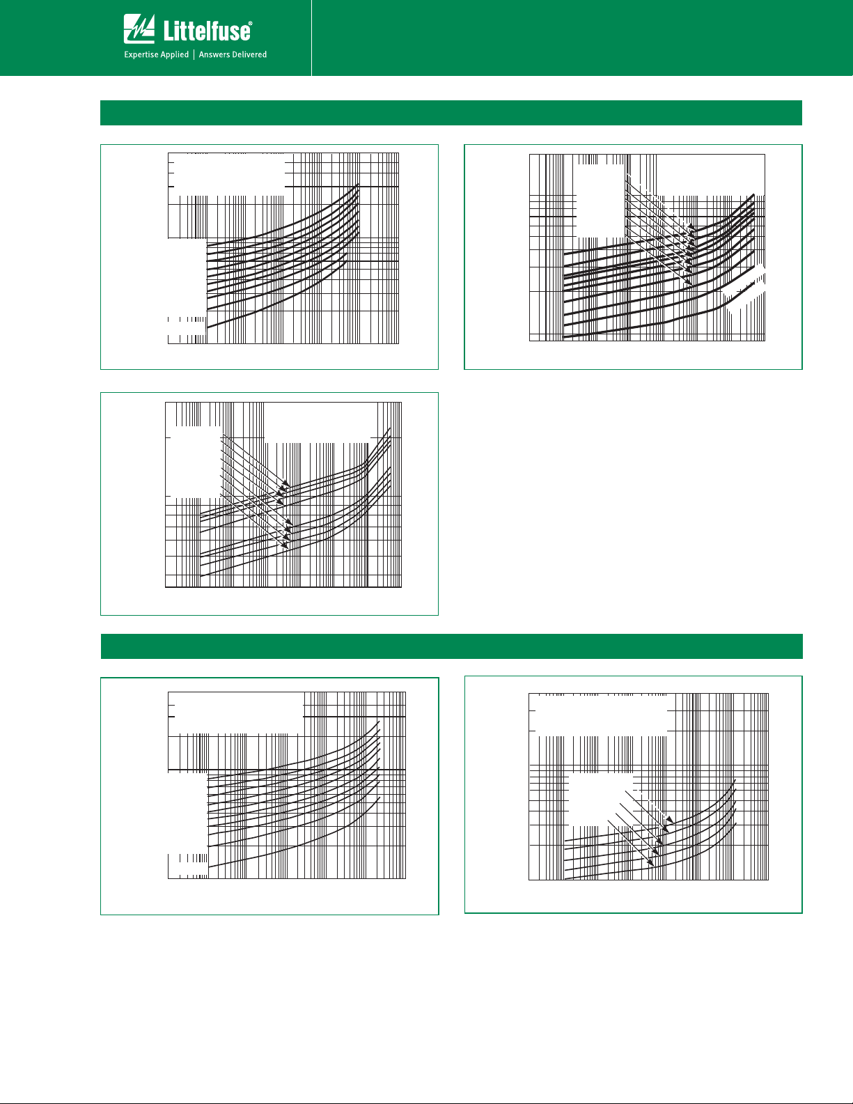
Maximum Clamping Voltage for 5mm Parts
2000
0
)
)
3
MAXIMUM PEAK VOLTS (V)
PEAK AMPERES (A)
V8ZA05(P) - V68ZA05(P)
MAX CLAMPING VOLTAGE
500
MODEL SIZE 5mm
400
8 TO 68V
300
= -55oC TO 85oC
T
A
200
100
90
V68ZA05(P)
80
V56ZA05(P)
70
V47ZA05(P)
60
50
V39ZA05(P)
V33ZA05(P)
40
V27ZA05(P)
V22ZA05(P)
30
MAXIMUM PEAK VOLTS (V)
V18ZA05(P)
V12ZA05(P)
20
V8ZA05(P)
10
-3
Figure 3
10
V360ZA05(P) - V750ZA05(P)
V750ZA05(P)
2000
V715ZA05(P)
V680ZA05(P)
V620ZA05(P)
V470ZA05(P)
V430ZA05(P)
V390ZA05(P)
V360ZA05(P)
1000
10
N(DC)
-2
RATING
10
-1
0
10
PEAK AMPERES (A)
MAX CLAMPING VOLTAGE
MODEL SIZE 5mm
360 TO 750V
T
= -55oC TO 85oC
A
10
1
N(DC)
Varistor Products
V82ZA05(P) - V33ZA05(P)
2
10
10
RATING
Figure 4
1000
500
200
MAXIMUM PEAK VOLTS (V)
100
MAX CLAMPING VOLTAGE
V330ZA05(P)
V270ZA05(P)
V240ZA05(P)
V220ZA05(P)
V205ZA05(P)
V180ZA05(P)
V150ZA05(P)
V120ZA05(P)
0 01 0 1 1 10 100 100
0 0010 0001
PEAK AMPERES (A)
MODEL SIZE 5mm
O 330V
82 T
T
= -55oC TO 85oC
A
N(DC)
RATING
V100ZA05(P
V82ZA05(P
MAXIMUM PEAK VOLTS (V)
500
Figure 5
0.01 0.1 1 10 100 10000.0010.0001
PEAK AMPERES (A)
Maximum Clamping Voltage for 7mm Parts
V8ZA1(P) - V68ZA2(P)
500
MAXIMUM CLAMPING VOLTAGE
400
MODEL SIZE 7mm
8 TO 68V
300
T
= -55oC TO 85oC
A
200
100
90
V68ZA2(P)
80
70
V56ZA2(P)
60
V47ZA1(P)
50
V39ZA1(P)
V33ZA1(P)
40
V27ZA1(P)
30
V22ZA1(P)
MAXIMUM PEAK VOLTS (V)
V18ZA1(P)
20
V12ZA1(P)
V8ZA1(P)
10
-3
10
Figure 6 Figure 7
RATING
N(DC)
-2
10
-1
10
PEAK AMPERES (A)
0
1
10
10
2
10
10
V82ZA2(P) - V180ZA1(P)
4,000
MAXIMUM CLAMPING VOLTAGE
MODEL SIZE 7mm
3,000
82 TO 180V
T
= -55oC TO 85oC
A
2,000
1,000
900
800
700
600
500
400
300
200
100
-3
10
V120ZA1(P)
V100ZA3(P)
V82ZA2(P)
10-210-110010110210
RATING
N(DC)
V180ZA1(P)
V150ZA1(P)
3
4
10
©2011 Littelfuse, Inc.
Revision: November 13, 2011
 Loading...