

Page 1
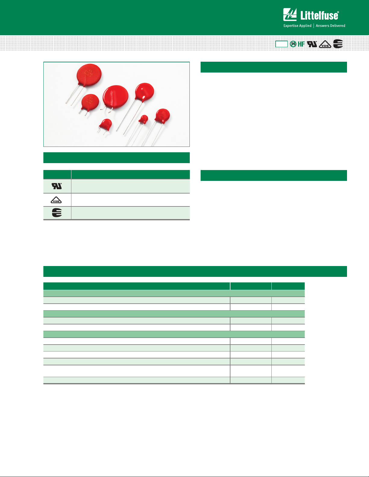
Varistor Products
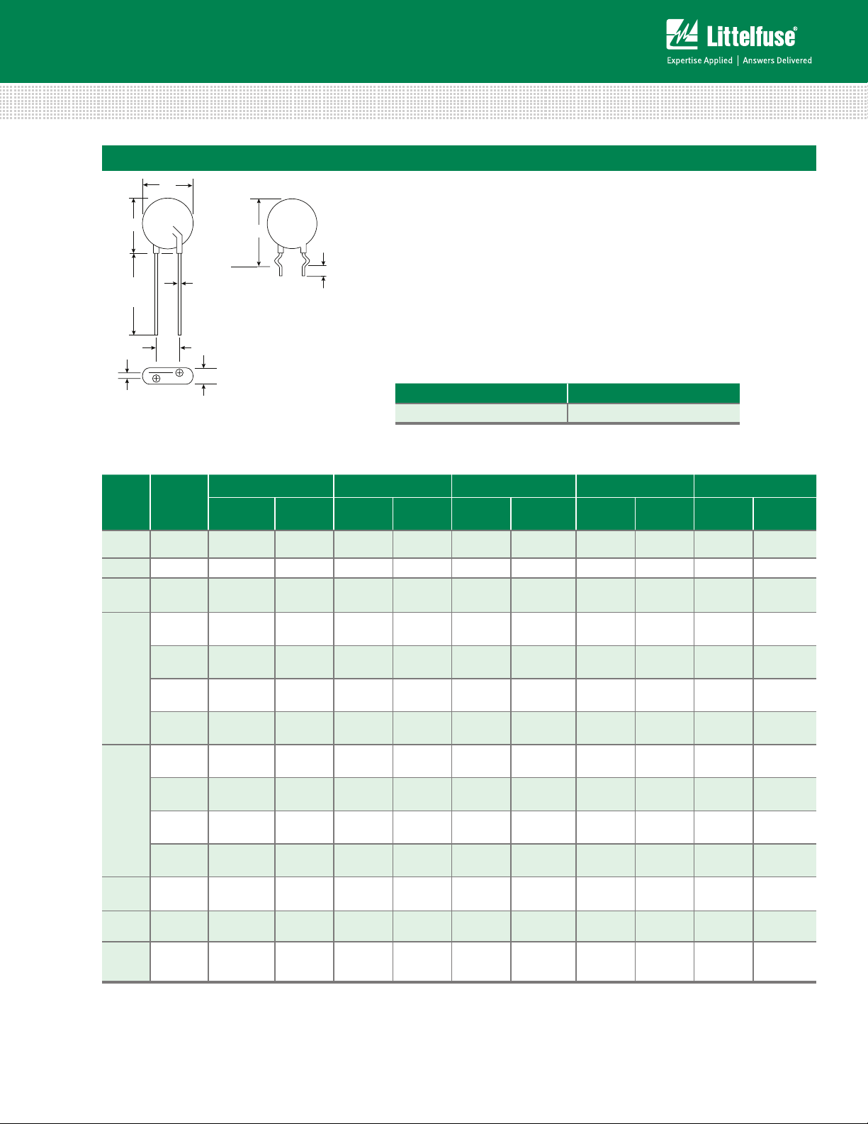
Radial Lead Varistors > ZA Series
ZA Varistor Series
Agency Approvals
Agency Agency File Number
E135010, (+ E320116 for selected parts)
116895
42201-006
RoHS
Description
The ZA Series of transient voltage surge suppressors
are radial leaded varistors (MOVs) designed for
use in the protection of low and medium-voltage
circuits and systems. Typical applications include
motor control, telecom, automotive systems,
solenoid, and power supply circuits to protect circuit
board components and maintain data integrity.
These devices are available in five model sizes:
5mm, 7mm, 10mm, 14mm and 20mm, and feature
a wide V
voltage range of 5.5V to 615V.
DC
See ZA Series Device Ratings and Specifications
Table for part number and brand information.
Features
• Lead–free, HalogenFree and RoHS
compliant
• Wide operating voltage
range V
M(AC)RMS
4V to 460V
• DC voltage ratings
5.5V to 615V
• No derating up to
85ºC ambient
• 5 model sizes
available: 5, 7, 10,
14, and 20mm
• Radial lead package for
hard-wired or printed
circuit board designs
• Available in tape and
reel or bulk pack
• Standard lead
form options
ZA Series
Absolute Maximum Ratings
• For ratings of individual members of a series, see Device Ratings and Specications chart
Continuous ZA Series Units
Steady State Applied Voltage:
AC Voltage Range (V
DC Voltage Range (V
Transients:
Peak Pulse Current (I
Single Pulse Energy Range (Note 1)
Operating Ambient Temperature Range (T
Storage Temperature Range (T
Temperature Coefficient (a
Hi-Pot Encapsulation (COATING Isolation Voltage Capability)
(Dielectric must withstand indicated DC voltage for one minute per MIL–STD–202, Method 301)
COATING Insulation Resistance 1000 MΩ
)
TM
For 8/20µs Current Wave (See Figure 2) 50 to 6500 A
For 10/1000µs Current Wave (W
) -55 to +125 ºC
STG
V
) of Clamping Voltage (VC) at Specified Test Current <0.01 %/ºC
CAUTION: Stresses above those listed in "Absolute Maximum Ratings" may cause permanent damage to the device. This is a stress only
rating and operation of the device at these or any other conditions above those indicated in the operational sections of this specification is
not implied.
) 4 to 460 V
M(AC)RMS
) 5.5 to 615 V
M(DC)
) 0.1 to 52 J
) -55 to +85 ºC
A
TM
2500 V
© 2014 Littelfuse, Inc.
Specifications are subject to change without notice.
Please refer to www.littelfuse.com/series/za.html for current information.
137
Revised: February 13, 2014
ZA Varistor Series
Page 2
Varistor Products
Radial Lead Varistors > ZA Series
ZA Series Ratings & Specifications
Maximum Rating (85°C) Specifications (25°C)
Part
Number
Branding
Model
Size
Disc Dia.
(mm)
Continuous Transient
RMS
V
V
V
V
M(AC)
DC
M(DC)
Energy 10
x 1000µs
WTM ITM
Peak
Current
8 x 20µs
Varistor Voltage at
1mA
DC Test Current
V
NOM
Min
V
Max
(V) (V) (J) (A) (V) (V) (V) (A) (pF)
V8ZA05P PZ08 5 4 5.5 0.1 50 6 11 30 1 2000
V8ZA1P P08Z1 7 4 5.5 0.4 100 6 11 22 2.5 4190
V8ZA2P P08Z2 10 4 5.5 0.8 250 6 11 20 5 7000
V12ZA05P PZ12 5 6 8 0.14 50 9 16 37 1 1700
V12ZA1P P12Z1 7 6 8 0.6 100 9 16 34 2.5 3350
V12ZA2P P12Z2 10 6 8 1. 2 250 9 16 30 5 6 10 0
V18ZA05P PZ18 5 10 14 0.17 100 14.4 21.6 36 1 140 0
V18ZA1P P18Z1 7 10 14 0.8 250 14.4 21.6 36 2.5 2700
V18ZA2P P18Z2 10 10 14 1. 5 500 14.4 21.6 36 5 5300
V18ZA3P P18Z3 14 10 14 3.5 1000 14.4 21.6 36 10 18870
V18ZA20P P18Z20 20 10 14 10 2000 14.4 21.6 37 20 22000
V18ZA40P P18Z40 20 10 14
80
(Note2)
2000
14.4
(Note 3)
21.6 37 20 22000
V22ZA05P PZ22 5 14 18 0.2 10 0 18.7 26 43 1 1220
V22ZA1P P22Z1 7 14 18 0.9 250 18.7 26 43 2.5 2375
V22ZA2P P22Z2 10 14 18 2 500 18.7 26 43 5 4500
V22ZA3P P22Z3 14 14 18 4 1000 18.7 26 43 10 14730
V24ZA20P P24Z20 20 14 18 12 2000 18.7 26 43 20 18000
V24ZA50P P24Z50 20 14
18
(Note 4)
100
(Note 2)
2000
19.2
(Note 3)
26 43 20 18000
V27ZA05P PZ27 5 17 22 0.25 10 0 23 31.1 53 1 920
V27ZA1P P27Z1 7 17 22 1 250 23 31.1 53 2.5 1875
V27ZA2P P27Z2 10 17 22 2.5 500 23 31.1 53 5 3850
V27ZA4P P27Z4 14 17 22 5 1000 23 31.1 53 10 11480
V27ZA20P P27Z20 20 17 22 14 2000 23 31.1 53 20 13000
V27ZA60P P27Z60 20 17 22 100
(Note 2) 2000
23
(Note 3)
31.1 50 20 13000
V33ZA05P PZ33 5 20 26 0.3 10 0 29.5 38 65 1 790
V33ZA1P P33Z1 7 20 26 1. 2 250 29.5 36.5 65 2.5 1620
V33ZA2P P33Z2 10 20
26 3 500 29.5 36.5 65 5 3495
V33ZA5P P33Z5 14 20 26 6 1000 29.5 36.5 65 10 9290
V33ZA20P P33Z20 20 20 26 18 2000 29.5 36.5 65 20 13000
V33ZA70P P33Z70 20 21 27
100
(Note 2)
2000
29.5
(Note 3)
36.5 58 20 13000
V36ZA20P P36Z20 20 23 28 20 2000 32 40 70 20 12000
V36ZA80P P36Z80 20 23 28
100
(Note 2)
2000
32
(Note 3)
40 63 20 12000
V39ZA05P PZ39 5 25 31 0.3 10 0 35 46 79 1 675
V39ZA1P P39Z1 7 25 31 1. 2 250 35 43 79 2.5 1350
V39ZA3P P39Z3 10 25 31 3 500 35 43 76 5 310 0
V39ZA6P P39Z6 14 25 31 7. 2 1000 35 43 76 10 7000
V39ZA20P P39Z20 20 25 31 20 2000 35 43 76 20 12000
V47ZA05P PZ47 5 30 38 0.4 10 0 42 55 93 1 585
V47ZA1P P47Z1 7 30 38 1. 8 250 42 52 93 2.5 1245
V47ZA3P P47Z3 10 30 38 4.5 500 42 52 93 5 2590
V47ZA7P P47Z7 14 30 38 8.8 1000 42 52 93 10 6270
V47ZA20P P47Z20 20 30
ZA Varistor Series
38
(Note 6)23(Note 7)
Revised: February 13, 2014
2000 42 52 93 20 11000
138
Please refer to www.littelfuse.com/series/za.html for current information.
NOM
Maximum
Clamping
Voltage
8 x 20µs
V
C
Specifications are subject to change without notice.
Typical
Capaci-
tance
f = 1MHz
IPK C
© 2014 Littelfuse, Inc.
Page 3
Varistor Products
Radial Lead Varistors > ZA Series
ZA Series Ratings & Specifications (Continued...)
Maximum Rating (85°C) Specifications (25°C)
Part
Number
Branding
Model
Size
Disc Dia.
(mm)
Continuous Transient
V
RMS
V
M(AC)VM(DC)
V
DC
Energy 10
x 1000µs
WTM ITM
Peak
Current
8 x 20µs
Varistor Voltage at
1mA
DC Test Current
V
NOM
Min
V
Max
(V) (V) (J) (A) (V) (V) (V) (A) (pF)
V56ZA05P PZ56 5 35 45 0.5 10 0 50 66 110 1 500
V56ZA2P P56Z2 7 35 45 2.3 250 50 62 110 2.5 1035
V56ZA3P P56Z3 10 35 45 5.5 500 50 62 110 5 2150
V56ZA8P P56Z8 14 35 45 10 1000 50 62 110 10 4840
V56ZA20P P56Z20 20 35 45 30 2000 50 62 110 20 10000
V68ZA05P PZ68 5 40 56 0.6 10 0 61 80 135 1 400
V68ZA2P P68Z2 7 40 56 3 250 61 75 135 2.5 910
V68ZA3P P68Z3 10 40 56 6.5 500 61 75 135 5 1850
V68ZA10P P68Z10 14 40 56 13 1000 61 75 135 10 3870
V68ZA20P P68Z20 20 40 56 33 2000 61 75 135 20 9000
V82ZA05P PZ82 5 50 68 2 400 73 97 135 5 355
V82ZA2P P82Z2 7 50 68 4 120 0 73 91 135 10 700
V82ZA4P P82Z4 10 50 68 8 2500 73 91 135 25 1485
V82ZA12P P82Z12 14 50 68 15 4500 73 91 145 50 3380
V82ZA20P P82Z20 20 50 68 25 6500 73 91 14 5 100 7000
V100ZA05P PZ100 5 60 81 2.5 400 90 117 165 5 3 10
V100ZA3P P100Z 7 60 81 5 120 0 90 110 165 10 600
V100ZA4P P100Z4 10 60 81 10 2500 90 110 165 25 1200
V100ZA15P P100Z15 14 60 81 20 4500 90 110 175 50 2900
V100ZA20P P100Z20 20 60 81 30 6500 90 110 17 5 100 6500
V120ZA05P PZ120 5 75 102 3 400 108 138 205 5 250
V120ZA1P P120Z 7 75 102 6 12 00 108 132 205 10 515
V120ZA4P P120Z4 10 75 10 2 12 2500 108 13 2 200 25 110 0
V120ZA6P P120Z6 14 75 102 22 4500 10 8 132 2 10 50 2450
V120ZA20P P120Z20 20 75 10 2 33 6500 10 8 132 210 100 5000
V150ZA05P PZ150 5 92 127 4 400 135 17 3 250 5 190
V150ZA1P PZ051 7 95 127 8 12 00 135 165 250 10 460
V150ZA4P
P150Z4 10 95 127 15 2500 135 165 250 25 860
V150ZA8P P150Z8 14 95 127 20 4500 135 16 5 250 50 19 10
V150ZA20P P150Z20 20 95 127 45 6500 135 16 5 250 100 3500
V180ZA05P PZ180 5 110 153 5 400 162 207 295 5 10 0
V180ZA1P P180Z 7 11 5 153 10 1200 162 198 300 10 320
V180ZA5P P180Z5 10 115 153 18 2500 16 2 198 300 25 465
V180ZA10P P180Z10 14 11 5 153 35 4500 162 19 8 300 50 119 0
V180ZA20P P180Z20 20 115 153 52 6500 162 19 8 300 100 2400
V205ZA05P PZ205 5 13 0 170 5.5 400 184 226 340 5 100
V220ZA05P PZ220 5 14 0 180 6 400 198 253 360 5 95
†
V240ZA05P PZ240 5 150 200 7 400 216 264 395 5 90
†
V270ZA05P PZ270 5 175 225 7. 5 400 243 3 11 455 5 75
†
V330ZA05P PZ330 5 210 275 9 400 297 380 540 5 70
†
V360ZA05P PZ360 5 230 300 9.5 400 324 396 595 5 60
†
V390ZA05P PZ390 5 250 330 10 400 351 449 650 5 80
†
V430ZA05P PZ430 5 275 369 11 400 387 495 710 5 75
†
V470ZA05P PZ470 5 300 385 12 400 420 517 775 5 70
†
V620ZA05P PZ620 5 385 505 13 400 558 682 1025 5 45
†
V680ZA05P PZ680 5 420 560 14 400 6 10 74 8 112 0 5 40
†
V715ZA05P PZ715 5 440 585 15.5 400 643 787 118 0 5 35
†
V750ZA05P PZ750 5 460 615 17 400 675 825 1240 5 30
Note:
1. Average power dissipation of transients not to exceed 0.2W, 0.25W, 0.4W, 0.6W or 1W for
model sizes 5mm, 7mm, 10mm, 14mm and 20mm, respectively.
2. Energy rating for impulse duration of 30ms minimum to one half of peak current (auto
Load Dump).
3. 10mA DC test current.
© 2014 Littelfuse, Inc.
Specifications are subject to change without notice.
Please refer to www.littelfuse.com/series/za.html for current information.
Revised: February 13, 2014
4. Also rated to withstand 24V for 5 minutes.
5. Higher voltages available, contact Littelfuse.
6. Also rated to withstand 48V for 5 minutes.
7. Energy rating for impulse duration of 30ms minimum to one half of peak current (Auto
Load Dump): 100J
† Also Recognized to UL 1449, Transient Voltage Surge Suppressors File E320116
139
NOM
Maximum
Clamping
Voltage
8 x 20µs
IPK C
V
C
Typical
Capaci-
tance
f = 1MHz
ZA Series
ZA Varistor Series
Page 4
Varistor Products
100
90
50
10
O
1
T
T
1
T
2
TIME
PERCENT OF PEAK VALUE
100
90
80
70
60
50
40
30
20
10
0
-55 50 60 70 80 90 100110 120130 140150
AMBIENT TEMPERATURE (
o
C)
PERCENT OF RATED VALUE
100
90
80
70
60
50
40
30
20
10
0
-55 50 60 70 80 90 100110 120130 140150
AMBIENT TEMPERATURE (
o
C)
PERCENT OF RATED VALUE
Radial Lead Varistors > ZA Series
Phenolic Coating Option -- ZA Series Varistors for Hi-Temperature Operating Conditions:
• Phenolic coated ZA Series devices are available with improved maximum operating temperature of 125°C
• These devices also have improved temperature cycling performance capability
• Ratings and specications are as per standard ZA Series except Hi–Pot
Encapsulation (Isolation Voltage Capability) = 500V
• To order: add 'X1347' to part number (e.g. V22ZA3PX1347)
• These devices are not UL, CSA, VDE or CECC certied
• Contact factory for further details
• Product marking:
Lead-Free,
Halogen-Free
& RoHS Compliant
Indicator
LF 9
P22P3
YYWW
Phenolic Coated
Option
Identifier
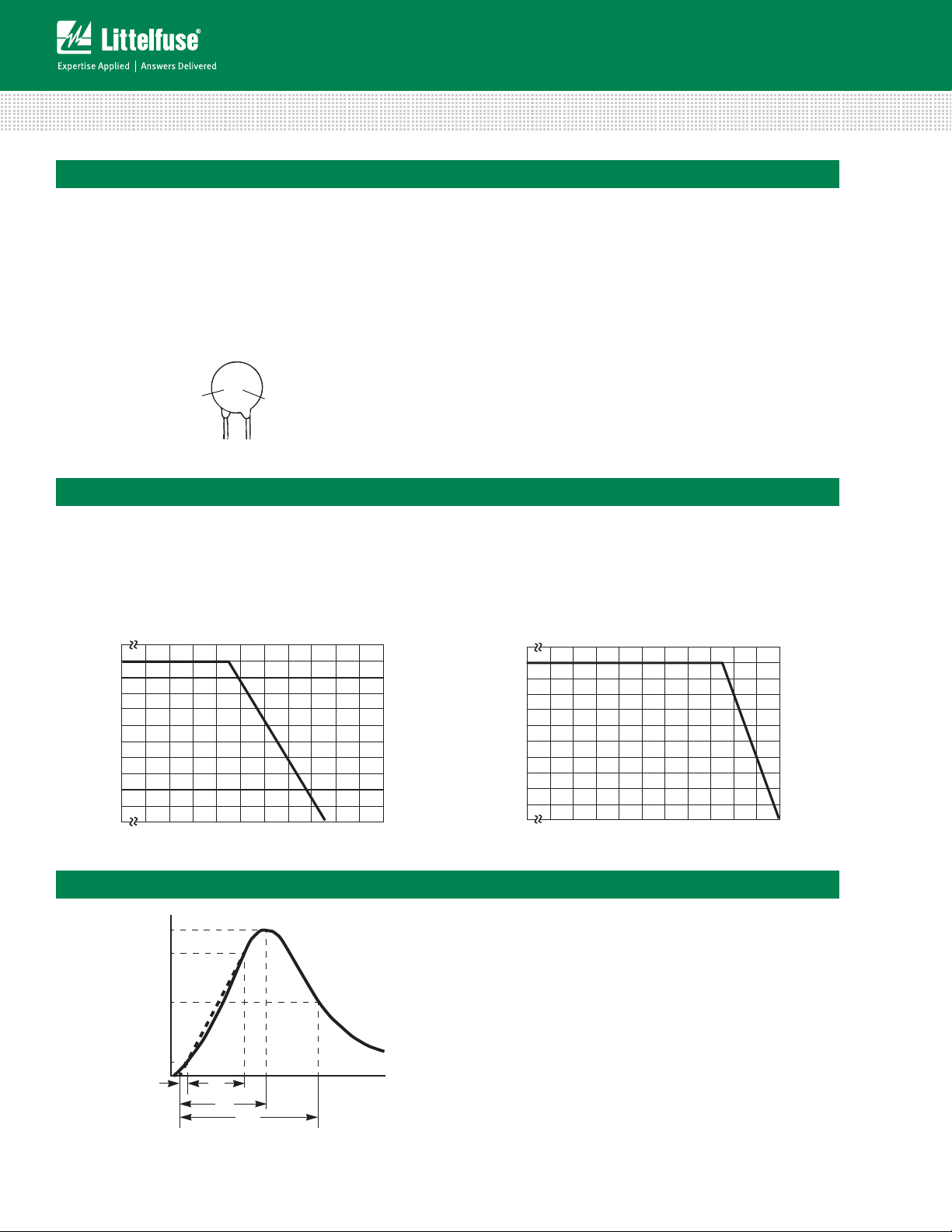
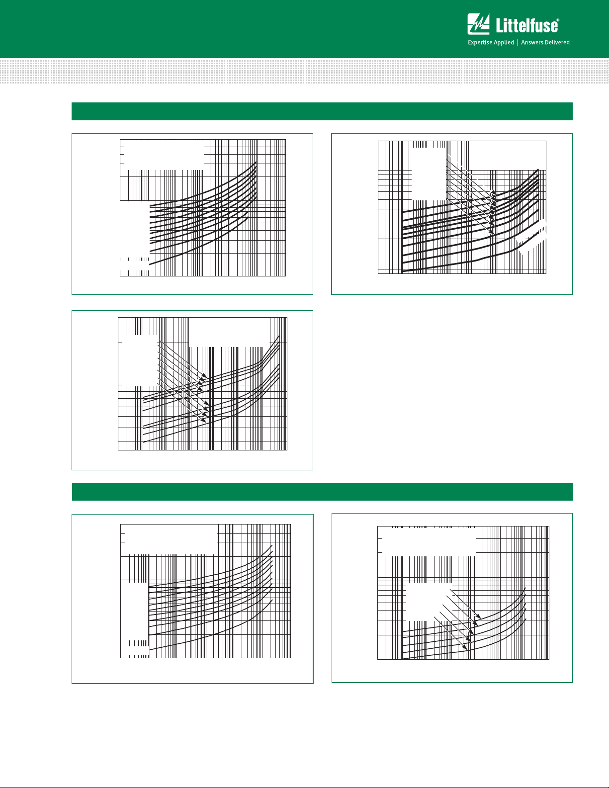
Current Energy and Power Dissipation Ratings
Should transients occur in rapid succession, the average
power dissipation is the energy (watt-seconds) per pulse
times the number of pulses per second. The power so
developed must be within the specifications shown on the
Device Ratings and Specifications Table for the specific
Figure 1A - Power Derating for Epoxy Coated
Peak Pulse Current Test Waveform
device. The operating values of a MOV need to be derated
at high temperatures as shown above. Because varistors
only dissipate a relatively small amount of average power
they are not suitable for repetitive applications that involve
substantial amounts of average power dissipation.
Figure 1B - Power Derating for Phenolic Coated
Figure 2
ZA Varistor Series
01 = Virtual Origin of Wave
T = Time from 10% to 90% of Peak
T1 = Rise Time = 1.25 x T
T2 = Decay Time
Example - For an 8/20 µs Current Waveform:
8µs = T1 = Rise Time
20µs = T2 = Decay Time
140
Revised: February 13, 2014
Please refer to www.littelfuse.com/series/za.html for current information.
Specifications are subject to change without notice.
© 2014 Littelfuse, Inc.
Page 5
Varistor Products
3000
2000
1000
500
MAXIMUM PEAK VOLTS (V)
PEAK AMPERES (A)
0.01 0.1 110100 10000.0010.0001
V750ZA05(P)
V715ZA05(P)
V680ZA05(P)
V620ZA05(P)
V470ZA05(P)
V430ZA05(P)
V390ZA05(P)
V360ZA05(P)
MAX CLAMPING VOLTAGE
MODEL SIZE 5mm
360 TO 750V
N(DC)
RATING
T
A
= -55oC TO 85oC
500
400
300
200
100
90
80
70
60
50
40
30
20
10
MAXIMUM PEAK VOLTS (V)
10
-3
10
-2
10
-1
10
0
10
1
10
2
10
3
MAXIMUM CLAMPING VOLTAGE
8 TO 68V
N(DC)
RATING
T
A
= -55oC TO 85oC
PEAK AMPERES (A)
V68ZA2(P)
V56ZA2(P)
V47ZA1(P)
V39ZA1(P)
V33ZA1(P)
V27ZA1(P)
V22ZA1(P)
V12ZA1(P)
V18ZA1(P)
V8ZA1(P)
MODEL SIZE 7mm
600
500
400
300
200
100
90
80
70
60
50
40
30
20
MAXIMUM PEAK VOLTS (V)
PEAK AMPERES (A)
10
-2
10
-1
10
0
10
1
10
2
10
3
MAX CLAMPING VOLTAGE
MODEL SIZE 5mm
8 TO 68V
N(DC)
RATING
T
A
= -55oC TO 85oC
10
V68ZA05(P)
V56ZA05(P)
V47ZA05(P)
V39ZA05(P)
V33ZA05(P)
V27ZA05(P)
V22ZA05(P)
V18ZA05(P)
V12ZA05(P)
V8ZA05(P)
10
-3
2000
1000
500
200
MAXIMUM PEAK VOLTS (V)
PEAK AMPERES (A)
0.01 0.1 110 100 1000
100
0.0010.0001
V100ZA05(P)
V82ZA05(P)
MAX CLAMPING VOLTAG E
MODEL SIZE 5mm
82 T
O 330V
N(DC)
RATING
T
A
= -55oC TO 85oC
V330ZA05(P)
V270ZA05(P)
V240ZA05(P)
V220ZA05(P)
V205ZA05(P)
V180ZA05(P)
V150ZA05(P)
V120ZA05(P)
500
400
300
200
100
90
80
70
60
50
40
30
20
10
MAXIMUM PEAK VOLTS (V)
10
-3
10
-2
10
-1
10
0
10
1
10
2
10
3
MAXIMUM CLAMPING VOLTAGE
8 TO 68V
N(DC)
RATING
T
A
= -55oC TO 85oC
PEAK AMPERES (A)
V68ZA2(P)
V56ZA2(P)
V47ZA1(P)
V39ZA1(P)
V33ZA1(P)
V27ZA1(P)
V22ZA1(P)
V12ZA1(P)
V18ZA1(P)
V8ZA1(P)
MODEL SIZE 7mm
FIGURE 5. CLAMPING VOLTAGE FOR V360ZA05(P) - V750ZA05(P) FIGURE 6. CLAMPING VOLTAGE FOR V8ZA1(P) - V68ZA2(P)
3000
2000
1000
500
MAXIMUM PEAK VOLTS (V)
PEAK AMPERES (A)
0.01 0.1 110100 10000.0010.0001
V750ZA05(P)
V715ZA05(P)
V680ZA05(P)
V620ZA05(P)
V470ZA05(P)
V430ZA05(P)
V390ZA05(P)
V360ZA05(P)
MAX CLAMPING VOLTAGE
MODEL SIZE 5mm
360 TO 750V
N(DC)
RATING
T
A
= -55oC TO 85oC
500
400
300
200
100
90
80
70
60
50
40
30
20
10
MAXIMUM PEAK VOLTS (V)
10
-3
10
-2
10
-1
10
0
10
1
10
2
10
3
MAXIMUM CLAMPING VOLTAGE
8 TO 68V
N(DC)
RATING
T
A
= -55oC TO 85oC
PEAK AMPERES (A)
V68ZA2(P)
V56ZA2(P)
V47ZA1(P)
V39ZA1(P)
V33ZA1(P)
V27ZA1(P)
V22ZA1(P)
V12ZA1(P)
V18ZA1(P)
V8ZA1(P)
MODEL SIZE 7mm
MAXIMUM PEAK VOLTS (V)
PEAK AMPERES (A)
10
-2
10
-1
10010110210
3
10
-3
MAXIMUM CLAMPING VOLTAGE
MODEL SIZE 7mm
82 TO 180V
N(DC)
RATING
T
A
= -55oC TO 85oC
4,000
3,000
2,000
1,000
900
800
700
600
500
400
300
200
100
10
4
V180ZA1(P)
V150ZA1(P)
V120ZA1(P)
V100ZA3(P)
V82ZA2(P)
500
400
300
200
100
90
80
70
60
50
40
30
20
10
MAXIMUM PEAK VOLTS (V)
10
-3
10
-2
10
-1
10
0
10
1
10
2
10
3
PEAK AMPERES (A)
V68ZA3(P)
V56ZA3(P)
V47ZA3(P)
V39ZA3(P)
V33ZA2(P)
V27ZA2(P)
V22ZA2(P)
V18ZA2(P)
V8ZA2(P)
V12ZA2(P)
MAXIMUM CLAMPING VOLTAGE
MODEL SIZE 10mm
8 TO 68V
N(DC)
RATING
T
A
= -55oC TO 85oC
Radial Lead Varistors > ZA Series
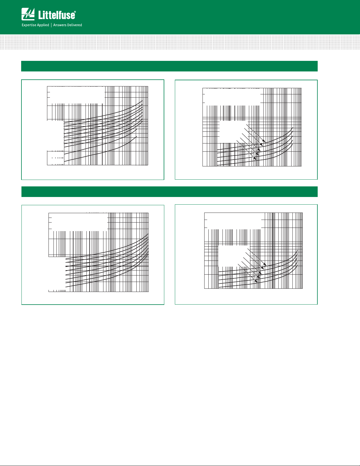
Maximum Clamping Voltage for 5mm Parts
V8ZA05(P) - V68ZA05(P)
V82ZA05(P) - V33ZA05(P)
Figure 3
V360ZA05(P) - V750ZA05(P)
Figure 5
Maximum Clamping Voltage for 7mm Parts
V8ZA1(P) - V68ZA2(P)
Figure 4
V82ZA2(P) - V180ZA1(P)
ZA Series
Figure 6 Figure 7
© 2014 Littelfuse, Inc.
Specifications are subject to change without notice.
Please refer to www.littelfuse.com/series/za.html for current information.
141
Revised: February 13, 2014
ZA Varistor Series
Page 6
Maximum Clamping Voltage for 10mm Parts
500
400
300
200
100
90
80
70
60
50
40
30
20
10
MAXIMUM PEAK VOLTS (V)
10
-3
10
-2
10
-1
10
0
10
1
10
2
10
3
MAXIMUM CLAMPING VOLTAGE
8 TO 68V
N(DC)
RATING
T
A
= -55oC TO 85oC
PEAK AMPERES (A)
V68ZA2(P)
V56ZA2(P)
V47ZA1(P)
V39ZA1(P)
V33ZA1(P)
V27ZA1(P)
V22ZA1(P)
V12ZA1(P)
V18ZA1(P)
V8ZA1(P)
MODEL SIZE 7mm
500
400
300
200
100
90
80
70
60
50
40
30
20
10
MAXIMUM PEAK VOLTS (V)
10
-3
10
-2
10
-1
10
0
10
1
10
2
10
3
PEAK AMPERES (A)
V68ZA3(P)
V56ZA3(P)
V47ZA3(P)
V39ZA3(P)
V33ZA2(P)
V27ZA2(P)
V22ZA2(P)
V18ZA2(P)
V8ZA2(P)
V12ZA2(P)
MAXIMUM CLAMPING VOLTAGE
MODEL SIZE 10mm
8 TO 68V
N(DC)
RATING
T
A
= -55oC TO 85oC
FIGURE 5. CLAMPING VOLTAGE FOR V360ZA05(P) - V750ZA05(P) FIGURE 6. CLAMPING VOLTAGE FOR V8ZA1(P) - V68ZA2(P)
FIGURE 7. CLAMPING VOLTAGE FOR V82ZA2(P) - V180ZA1(P) FIGURE 8. CLAMPING VOLTAGE FOR V8ZA2(P) - V68ZA3(P)
3000
2000
1000
500
MAXIMUM PEAK VOLTS (V)
PEAK AMPERES (A)
0.01 0.1 110100 10000.0010.0001
V750ZA05(P)
V715ZA05(P)
V680ZA05(P)
V620ZA05(P)
V470ZA05(P)
V430ZA05(P)
V390ZA05(P)
V360ZA05(P)
MAX CLAMPING VOLTAGE
MODEL SIZE 5mm
360 TO 750V
N(DC)
RATING
T
A
= -55oC TO 85oC
500
400
300
200
100
90
80
70
60
50
40
30
20
10
MAXIMUM PEAK VOLTS (V)
10
-3
10
-2
10
-1
10
0
10
1
10
2
10
3
MAXIMUM CLAMPING VOLTAGE
8 TO 68V
N(DC)
RATING
T
A
= -55oC TO 85oC
PEAK AMPERES (A)
V68ZA2(P)
V56ZA2(P)
V47ZA1(P)
V39ZA1(P)
V33ZA1(P)
V27ZA1(P)
V22ZA1(P)
V12ZA1(P)
V18ZA1(P)
V8ZA1(P)
MODEL SIZE 7mm
MAXIMUM PEAK VOLTS (V)
PEAK AMPERES (A)
10
-2
10
-1
10010110210
3
10
-3
MAXIMUM CLAMPING VOLTAGE
MODEL SIZE 7mm
82 TO 180V
N(DC)
RATING
T
A
= -55oC TO 85oC
4,000
3,000
2,000
1,000
900
800
700
600
500
400
300
200
100
10
4
V180ZA1(P)
V150ZA1(P)
V120ZA1(P)
V100ZA3(P)
V82ZA2(P)
500
400
300
200
100
90
80
70
60
50
40
30
20
10
MAXIMUM PEAK VOLTS (V)
10
-3
10
-2
10
-1
10
0
10
1
10
2
10
3
PEAK AMPERES (A)
V68ZA3(P)
V56ZA3(P)
V47ZA3(P)
V39ZA3(P)
V33ZA2(P)
V27ZA2(P)
V22ZA2(P)
V18ZA2(P)
V8ZA2(P)
V12ZA2(P)
MAXIMUM CLAMPING VOLTAGE
MODEL SIZE 10mm
8 TO 68V
N(DC)
RATING
T
A
= -55oC TO 85oC
MAXIMUM PEAK VOLTS (V)
PEAK AMPERES (A)
10
-2
10
-1
10010110210
3
10
-3
MAXIMUM CLAMPING VOLTAGE
MODEL SIZE 10mm
82 TO 180V
N(DC)
RATING
T
A
= -55oC TO 85oC
4,000
3,000
2,000
1,000
900
800
700
600
500
400
300
200
100
10
4
V180ZA5(P)
V150ZA4(P)
V120ZA4(P)
V100ZA4(P)
V82ZA4(P)
600
500
400
300
200
100
90
80
70
60
50
40
30
20
10
-3
10
-2
10
-1
10
0
10
1
10
2
10
3
PEAK AMPERES (A)
MAXIMUM PEAK VOLTS (V)
V68ZA10(P)
V56ZA8(P)
V47ZA7(P)
V39ZA6(P)
V33ZA5(P)
V27ZA4(P)
V22ZA3(P)
V18ZA3(P)
MAXIMUM CLAMPING VOLTAGE
18 TO 68V
N(DC)
RATING
T
A
= -55oC TO 85oC
MODEL SIZE 14mm
500
400
300
200
100
90
80
70
60
50
40
30
20
10
MAXIMUM PEAK VOLTS (V)
10
-3
10
-2
10
-1
10
0
10
1
10
2
10
3
MAXIMUM CLAMPING VOLTAGE
8 TO 68V
N(DC)
RATING
T
A
= -55oC TO 85oC
PEAK AMPERES (A)
V68ZA2(P)
V56ZA2(P)
V47ZA1(P)
V39ZA1(P)
V33ZA1(P)
V27ZA1(P)
V22ZA1(P)
V12ZA1(P)
V18ZA1(P)
V8ZA1(P)
MODEL SIZE 7mm
500
400
300
200
100
90
80
70
60
50
40
30
20
10
MAXIMUM PEAK VOLTS (V)
10
-3
10
-2
10
-1
10
0
10
1
10
2
10
3
PEAK AMPERES (A)
V68ZA3(P)
V56ZA3(P)
V47ZA3(P)
V39ZA3(P)
V33ZA2(P)
V27ZA2(P)
V22ZA2(P)
V18ZA2(P)
V8ZA2(P)
V12ZA2(P)
MAXIMUM CLAMPING VOLTAGE
MODEL SIZE 10mm
8 TO 68V
N(DC)
RATING
T
A
= -55oC TO 85oC
600
500
400
300
200
100
90
80
70
60
50
40
30
20
10
-3
10
-2
10
-1
10
0
10
1
10
2
10
3
PEAK AMPERES (A)
MAXIMUM PEAK VOLTS (V)
V68ZA10(P)
V56ZA8(P)
V47ZA7(P)
V39ZA6(P)
V33ZA5(P)
V27ZA4(P)
V22ZA3(P)
V18ZA3(P)
MAXIMUM CLAMPING VOLTAGE
18 TO 68V
N(DC)
RATING
T
A
= -55oC TO 85oC
MODEL SIZE 14mm
Transient V-I Characteristic Curves
(Continued)
PEAK AMPERES (A)
10
-2
10-110010110210
3
10
-3
MAXIMUM CLAMPING VOLTAGE
MODEL SIZE 14mm
82 TO 180V
N(DC)
RATING
T
A
= -55oC TO 85oC
4,000
3,000
2,000
1,000
900
800
700
600
500
400
300
200
100
10
4
V180ZA10(P)
V150ZA8(P)
V120ZA6(P)
V100ZA15(P)
V82ZA12(P)
300
200
100
90
80
70
60
50
40
30
20
MAXIMUM PEAK VOLTS (V)
MAXIMUM PEAK VOLTS (V)
PEAK AMPERES (A)
10
-2
10-110010110210
3
10
-3
10
4
MAXIMUM CLAMPING VOLTAGE
MODEL SIZE 20mm
18 TO 36V
N(DC)
RATING
T
A
= -55oC TO 85oC
V36ZA20(P) V36ZA80(P)
V33ZA20(P) V33ZA70(P)
V27ZA60(P) V27ZA60(P)
V24ZA50(P) V24ZA50(P)
V18ZA40P(P) V18ZA40P(P)
V8ZA2(P) - V68ZA3(P)
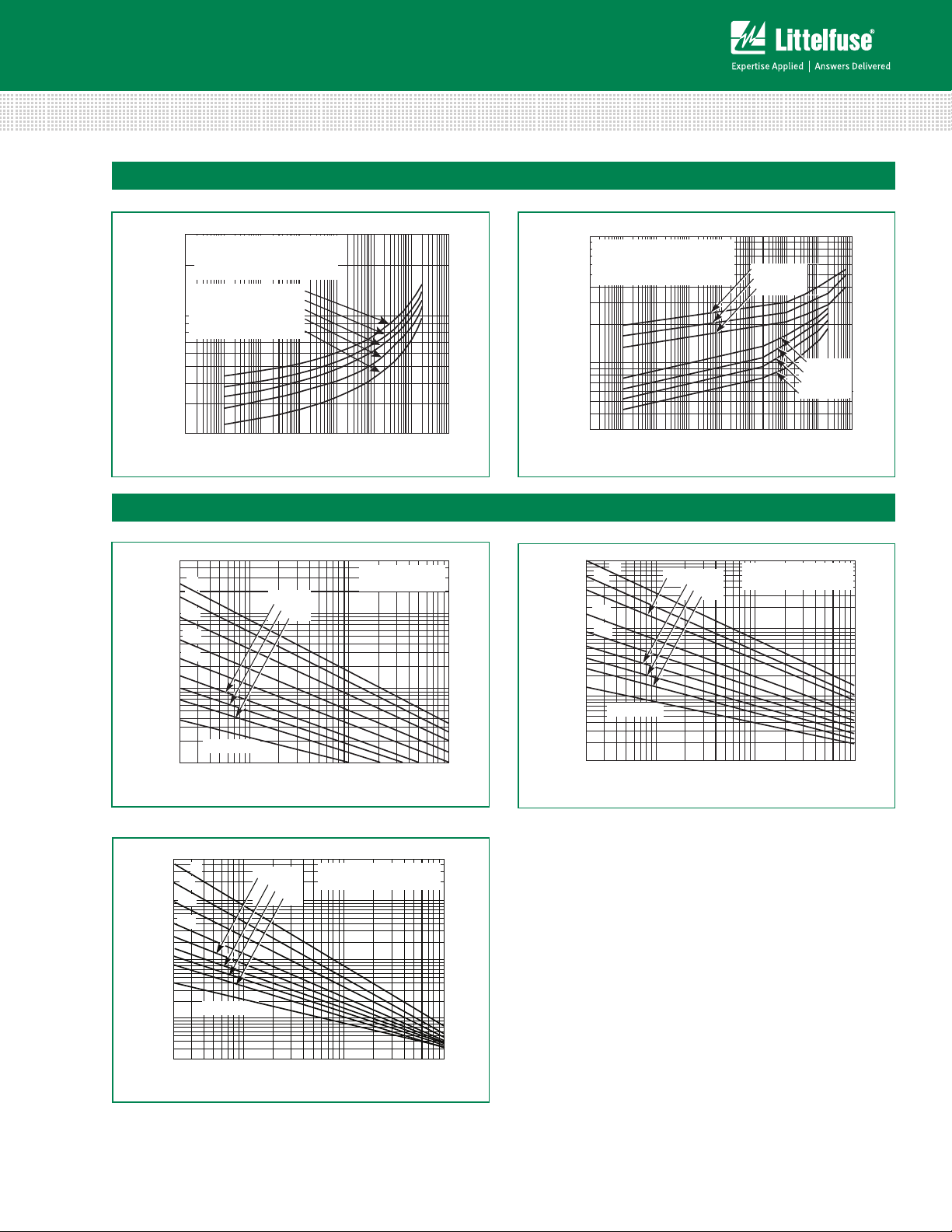
Figure 8 Figure 9
Maximum Clamping Voltage for 14mm Parts
V18ZA3(P) - V68ZA10(P)
Varistor Products
Radial Lead Varistors > ZA Series
V82ZA4(P) - V180ZA5(P)
V82ZA12(P) - V180ZA10(P)
Figure 10 Figure 11
ZA Varistor Series
142
Revised: February 13, 2014
Please refer to www.littelfuse.com/series/za.html for current information.
© 2014 Littelfuse, Inc.
Specifications are subject to change without notice.
Page 7
Varistor Products
300
200
100
90
80
70
60
50
40
30
20
MAXIMUM PEAK VOLTS (V)
PEAK AMPERES (A)
10
-2
10-110010110210
3
10
-3
10
4
MAXIMUM CLAMPING VOLTAGE
MODEL SIZE 20mm
18 TO 36V
N(DC)
RATING
T
A
= -55oC TO 85oC
V36ZA20(P) V36ZA80(P)
V33ZA20(P) V33ZA70(P)
V27ZA60(P) V27ZA60(P)
V24ZA50(P) V24ZA50(P)
V18ZA40P(P) V18ZA40P(P)
(Continued)
0101
10210
3104
300
200
100
90
80
70
60
50
40
30
20
MAXIMUM PEAK VOLTS (V)
PEAK AMPERES (A)
10
-2
10-110010110210
3
10
-3
10
4
MAXIMUM CLAMPING VOLTAGE
MODEL SIZE 20mm
18 TO 36V
N(DC)
RATING
T
A
= -55oC TO 85oC
V36ZA20(P) V36ZA80(P)
V33ZA20(P) V33ZA70(P)
V27ZA60(P) V27ZA60(P)
V24ZA50(P) V24ZA50(P)
V18ZA40P(P) V18ZA40P(P)
10-310-210-110010110
2
10
4
10
3
1,000
500
300
200
30
PEAK AMPERES (A)
MAXIMUM PEAK VOLTS (V)
V56ZA20(P)
V47ZA20(P)
V39ZA20(P)
MAXIMUM CLAMPING VOLTAGE
MODEL SIZE 20mm
T
A
= -55oC TO 85oC
39 TO 180V
M(AC )
RATING
V180ZA20(P)
V150ZA20(P)
V120ZA20(P)
100
50
V68ZA20(P)
FIGURE 11. CLAMPING VOLTAGE FOR V82ZA12(P) - V180ZA10(P) FIGURE 12. CLAMPING VOLTAGE FOR V18ZA40(P) - V36ZA80(P)
FIGURE 13. CLAMPING VOLTAGE FOR V39ZA20(P) - V180ZA20(P)
Transient V-I Characteristic Curves
(Continued)
PEAK AMPERES (A)
10
-2
10-110010110210
3
10
-3
MAXIMUM CLAMPING VOLTAGE
MODEL SIZE 14mm
82 TO 180V
N(DC)
RATING
T
A
= -55oC TO 85oC
4,000
3,000
2,000
1,000
900
800
700
600
500
400
300
200
100
10
4
V180ZA10(P)
V150ZA8(P)
V120ZA6(P)
V100ZA15(P)
V82ZA12(P)
300
200
100
90
80
70
60
50
40
30
20
MAXIMUM PEAK VOLTS (V)
MAXIMUM PEAK VOLTS (V)
PEAK AMPERES (A)
10
-2
10-110010110210
3
10
-3
10
4
MAXIMUM CLAMPING VOLTAGE
MODEL SIZE 20mm
18 TO 36V
N(DC)
RATING
T
A
= -55oC TO 85oC
V36ZA20(P) V36ZA80(P)
V33ZA20(P) V33ZA70(P)
V27ZA60(P) V27ZA60(P)
V24ZA50(P) V24ZA50(P)
V18ZA40P(P) V18ZA40P(P)
10-310-210-110010110
2
10
4
10
3
1,000
500
300
200
30
PEAK AMPERES (A)
MAXIMUM PEAK VOLTS (V)
V56ZA20(P)
V47ZA20(P)
V39ZA20(P)
MAXIMUM CLAMPING VOLTAGE
MODEL SIZE 20mm
T
A
= -55oC TO 85oC
39 TO 180V
M(AC )
RATING
V180ZA20(P)
V150ZA20(P)
V120ZA20(P)
100
50
V68ZA20(P)
Pulse Rating Curves
50
20
10
5
2
1
0.5
0.2
0.1
SURGE CURRENT (A)
20 100 1,000 10,000
IMPULSE DURATION (μs)
1
10
10
2
2
10
3
INDEFINITE
10
4
10
5
10
6
MODEL SIZE 5mm
V8ZA05(P)
100
50
20
10
2
1
0.5
0.2
0.1
SURGE CURRENT (A)
20 100 1,000 10,000
INDEFINITE
10
4
10
5
10
6
MODEL SIZE 5mm
V12ZA05(P) - V68ZA05(P)
1
10
10
2
2
10
3
IMPULSE DURATION (μs)
300
200
100
90
80
70
60
50
40
30
20
MAXIMUM PEAK VOLTS (V)
PEAK AMPERES (A)
10
-2
10-110010110210
3
10
-3
10
4
MAXIMUM CLAMPING VOLTAGE
MODEL SIZE 20mm
18 TO 36V
N(DC)
RATING
T
A
= -55oC TO 85oC
V36ZA20(P) V36ZA80(P)
V33ZA20(P) V33ZA70(P)
V27ZA60(P) V27ZA60(P)
V24ZA50(P) V24ZA50(P)
V18ZA40P(P) V18ZA40P(P)
10110
2
10
4
10
3
V56ZA20(P)
V47ZA20(P)
V39ZA20(P)
V180ZA20(P)
V150ZA20(P)
V120ZA20(P)
V68ZA20(P)
100
50
20
10
2
1
0.5
0.2
0.1
SURGE CURRENT (A)
20 100 1,000 10,000
INDEFINITE
10
4
10
5
10
6
MODEL SIZE 5mm
V12ZA05(P) - V68ZA05(P)
1
10
10
2
2
10
3
IMPULSE DURATION (μs)
50
20
10
5
2
1
0.5
0.2
SURGE CURRENT (A)
20 100 1,000 10,000
IMPULSE DURATION ( µs)
1
10
10
2
2
10
3
INDEFINITE
10
4
10
5
10
6
MODEL SIZE 5mm
V82ZA05(P) - V750ZA05(P)
500
200
100
20 100 1,000 10,000
IMPULSE DURATION ( µs)
SURGE CURRENT (A)
1
10
10
2
2
10
3
INDEFINITE
10
4
10
5
10
6
200
100
50
20
10
5
2
1
0.5
0.2
MODEL SIZE 7mm
V8ZA1(P) - V12ZA1(P)
Radial Lead Varistors > ZA Series
Maximum Clamping Voltage for 20mm Parts
V18ZA20(P) - V36ZA80(P)
V39ZA20(P) - V180ZA20(P)
Figure 11 Figure 12
Repetitive Surge Capability for 5mm Parts
V8ZA05(P)
V12ZA05(P) - V68ZA05(P)
Figure 13 Figure 14
V82ZA05(P) - V750ZA05(P)
ZA Series
Figure 15
© 2014 Littelfuse, Inc.
Specifications are subject to change without notice.
Please refer to www.littelfuse.com/series/za.html for current information.
Revised: February 13, 2014
143
ZA Varistor Series
Page 8
Varistor Products
20 100 1,000 10,000
IMPULSE DURATION ( µs)
SURGE CURRENT (A)
1
10
10
2
2
10
3
INDEFINITE
10
4
10
5
10
6
200
100
50
20
10
5
2
1
0.5
0.2
MODEL SIZE 7mm
V8ZA1(P) - V12ZA1(P)
FIGURE 16. SURGE CURRENT RATING CURVES FOR
V82ZA05(P) - V750ZA05(P)
FIGURE 17. SURGE CURRENT RATING CURVES FOR
V8ZA1(P) - V12ZA1(P)
50
20
10
5
2
1
0.5
0.2
SURGE CURRENT (A)
20 100 1,000 10,000
IMPULSE DURATION ( µs)
1
10
10
2
2
10
3
INDEFINITE
10
4
10
5
10
6
MODEL SIZE 5mm
V82ZA05(P) - V750ZA05(P)
500
200
100
20 100 1,000 10,000
IMPULSE DURATION ( µs)
SURGE CURRENT (A)
1
10
10
2
2
10
3
INDEFINITE
10
4
10
5
10
6
200
100
50
20
10
5
2
1
0.5
0.2
MODEL SIZE 7mm
V8ZA1(P) - V12ZA1(P)
20 100 1,000 10,000
IMPULSE DURATION ( µs)
SURGE CURRENT (A)
1
10
10
2
2
10
3
INDEFINITE
500
200
100
50
20
10
2
1
0.5
0.2
10
4
10
5
10
6
5
MODEL SIZE 7mm
V18ZA1(P) - V68ZA2(P)
2,000
1,000
200
100
50
20
10
5
1
2
500
20 100 1,000 10,000
IMPULSE DURATION ( µs)
SURGE CURRENT (A)
1
2
10
10
2
10
4
10
5
10
6
10
3
INDEFINITE
MODEL SIZE 7mm
V82ZA2(P) - V180ZA1(P)
FIGURE 17. SURGE CURRENT RATING CURVES FOR
V8ZA1(P) - V12ZA1(P)
20 100 1,000 10,000
IMPULSE DURATION ( µs)
SURGE CURRENT (A)
1
10
10
2
2
10
3
INDEFINITE
10
4
10
5
10
6
200
100
50
20
10
5
2
1
0.5
0.2
MODEL SIZE 7mm
V8ZA1(P) - V12ZA1(P)
2,000
1,000
200
100
50
20
10
5
1
2
500
20 100 1,000 10,000
IMPULSE DURATION ( µs)
SURGE CURRENT (A)
1
2
10
10
2
10
4
10
5
10
6
10
3
INDEFINITE
MODEL SIZE 7mm
V82ZA2(P) - V180ZA1(P)
FIGURE 17. SURGE CURRENT RATING CURVES FOR
V8ZA1(P) - V12ZA1(P)
FIGURE 19. SURGE CURRENT RATING CURVES FOR
V82ZA2(P) - V180ZA1(P)
20 100 1,000 10,000
IMPULSE DURATION ( µs)
SURGE CURRENT (A)
1
10
10
2
2
10
3
INDEFINITE
10
4
10
5
10
6
200
100
50
20
10
5
2
1
0.5
0.2
MODEL SIZE 7mm
V8ZA1(P) - V12ZA1(P)
2,000
1,000
200
100
50
20
10
5
1
2
500
20 100 1,000 10,000
IMPULSE DURATION ( µs)
SURGE CURRENT (A)
1
2
10
10
2
10
4
10
5
10
6
10
3
INDEFINITE
MODEL SIZE 7mm
V82ZA2(P) - V180ZA1(P)
1,000
500
100
50
20
10
5
1
2
200
20
SURGE CURRENT (A)
1
2
10
5
10
6
10
4
INDEFINITE
MODEL SIZE 10mm
V18ZA2(P) - V68ZA3(P)
100 1,000 10,000
IMPULSE DURATION ( µs)
10
2
10
3
FIGURE 16. SURGE CURRENT RATING CURVES FOR
V82ZA05(P) - V750ZA05(P)
FIGURE 17. SURGE CURRENT RATING CURVES FOR
V8ZA1(P) - V12ZA1(P)
FIGURE 18. SURGE CURRENT RATING CURVES FOR
V18ZA1(P) - V68ZA2(P)
FIGURE 19. SURGE CURRENT RATING CURVES FOR
V82ZA2(P) - V180ZA1(P)
50
20
10
5
2
1
0.5
0.2
SURGE CURRENT (A)
20 100 1,000 10,000
IMPULSE DURATION ( µs)
1
10
10
2
2
10
3
INDEFINITE
10
4
10
5
10
6
MODEL SIZE 5mm
V82ZA05(P) - V750ZA05(P)
500
200
100
20 100 1,000 10,000
IMPULSE DURATION ( µs)
SURGE CURRENT (A)
1
10
10
2
2
10
3
INDEFINITE
10
4
10
5
10
6
200
100
50
20
10
5
2
1
0.5
0.2
MODEL SIZE 7mm
V8ZA1(P) - V12ZA1(P)
20 100 1,000 10,000
IMPULSE DURATION ( µs)
SURGE CURRENT (A)
1
10
10
2
2
10
3
INDEFINITE
500
200
100
50
20
10
2
1
0.5
0.2
10
4
10
5
10
6
5
MODEL SIZE 7mm
V18ZA1(P) - V68ZA2(P)
2,000
1,000
200
100
50
20
10
5
1
2
500
20 100 1,000 10,000
IMPULSE DURATION ( µs)
SURGE CURRENT (A)
1
2
10
10
2
10
4
10
5
10
6
10
3
INDEFINITE
MODEL SIZE 7mm
V82ZA2(P) - V180ZA1(P)
20 100 1,000 10,000
IMPULSE DURATION ( µs)
SURGE CURRENT (A)
1
10
10
2
2
10
3
INDEFINITE
500
200
100
50
20
10
2
1
0.5
0.2
10
4
10
5
10
6
5
MODEL SIZE 10mm
V8ZA2(P) - V12ZA2(P)
1,000
500
100
50
20
10
5
1
2
200
20
SURGE CURRENT (A)
1
2
10
5
10
6
10
4
INDEFINITE
MODEL SIZE 10mm
V18ZA2(P) - V68ZA3(P)
100 1,000 10,000
IMPULSE DURATION ( µs)
10
2
10
3
5,000
2,000
1,000
500
200
100
50
20
10
5
2
20 100 1,000 10,000
IMPULSE DURATION ( µs)
SURGE CURRENT (A)
1
10
10
2
2
10
3
INDEFINITE
10
4
10
5
10
6
MODEL SIZE 10mm
V82ZA4(P) - V180ZA5(P)
200
100
50
20
10
5
1
2
20 100 1,000 10,000
IMPULSE DURATION ( µs)
SURGE CURRENT (A)
1
2
10
10
2
10
4
10
5
10
6
10
3
INDEFINITE
1,000
500
MODEL SIZE 14mm
V18ZA3(P) - V68ZA10(P)
Radial Lead Varistors > ZA Series
Repetitive Surge Capability for 7mm Parts
V8ZA1(P) - V12ZA1(P)
Figure 15 Figure 18
V18ZA1(P) - V68ZA2(P)
Figure 16 Figure 19
V82ZA2(P) - V180ZA1(P)
Figure 17 Figure 20
ZA Varistor Series
Repetitive Surge Capability for 10mm Parts
V8ZA2(P) - V127ZA2(P)
V18ZA2(P) - V68ZA3(P)
Revised: February 13, 2014
V82ZA4(P) - V180ZA5(P)
144
Please refer to www.littelfuse.com/series/za.html for current information.
Specifications are subject to change without notice.
© 2014 Littelfuse, Inc.
Page 9

Varistor Products
200
100
50
20
10
5
1
2
20 100 1,000 10,000
IMPULSE DURATION ( µs)
SURGE CURRENT (A)
1
2
10
10
2
10
4
10
5
10
6
10
3
INDEFINITE
1,000
500
MODEL SIZE 14mm
V18ZA3(P) - V68ZA10(P)
5,000
2,000
200
100
50
20
10
5
2
500
20 100 1,000 10,000
IMPULSE DURATION ( µs)
SURGE CURRENT (A)
1
2
10
10
4
10
5
10
6
10
3
INDEFINITE
1,000
10
2
MODEL SIZE 14mm
V82ZA12(P) - V180ZA10(P)
2,000
200
100
50
20
10
5
2
500
20 100 1,000 10,000
IMPULSE DURATION ( µs)
SURGE CURRENT (A)
1
2
10
1,000
10
2
10
3
10
4
10
5
10
6
INDEFINITE
MODEL SIZE 20mm
V18ZA40(P) - V68ZA20(P)
FIGURE 25. SURGE CURRENT RATING CURRENT FOR
V18ZA40(P) - V68ZA20(P)
10
4
10
5
10
6
10
3
10
2
MODEL SIZE 14mm
V82ZA12(P) - V180ZA10(P)
2,000
200
100
50
20
10
5
2
500
20 100 1,000 10,000
IMPULSE DURATION ( µs)
SURGE CURRENT (A)
1
2
10
1,000
10
2
10
3
10
4
10
5
10
6
INDEFINITE
MODEL SIZE 20mm
V18ZA40(P) - V68ZA20(P)
10,0001,000100
20
IMPULSE DURATION ( µs)
SURGE CURRENT (A)
5,000
10,000
2,000
500
100
20
10
2
1,000
200
50
1
5
1
2
10
10
2
10
3
10
4
10
5
10
6
INDEFINITE
MODEL SIZE 20mm
V120ZA20(P) - V180ZA20(P)
2,000
200
100
50
20
10
5
2
500
20 100 1,000 10,000
IMPULSE DURATION ( µs)
SURGE CURRENT (A)
1
2
10
1,000
10
2
10
3
10
4
10
5
10
6
INDEFINITE
MODEL SIZE 20mm
V18ZA40(P) - V68ZA20(P)
Radial Lead Varistors > ZA Series
Repetitive Surge Capability for 14mm Parts
V18ZA3(P) - V68ZA10(P)
V82ZA12(P) - V180ZA10(P)
Figure 21 Figure 22
Repetitive Surge Capability for 20mm Parts
V18ZA40(P) - V68ZA20(P)
V120ZA20(P) - V180ZA20(P)
ZA Series
Figure 23 Figure 24
NOTE: If pulse ratings are exceeded, a shift of V
in a decrease of V
function, and to provide ample protection.
, may result in the device not meeting the original published specifications, but does not prevent the device from continuing to
N(DC)
© 2014 Littelfuse, Inc.
Specifications are subject to change without notice.
Please refer to www.littelfuse.com/series/za.html for current information.
(at specified current) of more then +/-10% could result. This type of shift, which normally results
N(DC)
145
Revised: February 13, 2014
ZA Varistor Series
Page 10

Wave Solder Profile
300
S)
TEMPERATURE (ºC)
300
TEMPERATURE (ºC)
Varistor Products
Radial Lead Varistors > ZA Series
Non Lead–free Profile
250
200
150
100
50
0
00.5 11.5 22.5 33.5 4
Figure 25 Figure 26
Maximum Wave 24 0C
TIME(MINUTE
Physical Specifications
Lead Material Copper Clad Steel Wire
Lead–free Profile
250
200
150
100
50
Environmental Specifications
Operating Ambient
Temperature Range
Soldering
Characteristics
Insulating Material
Device Labeling
Solderability per MIL–STD–202,
Method 208E
Cured, flame retardant epoxy polymer
meets UL94V–0 requirements
Marked with LF, voltage, UL/CSA logos,
and date code
Storage Temperature Range -55°C to +125°C
Humidity Aging
Thermal Shock
Maximum Wave 26 0C
0
00.5 11.5 22.5 33.5 4
TIME(MINUTES)
-55°C to +85°C
+85°C, 85% RH,1000 hours
+/-10% typical voltage change
+85°C to -40°C 5 times
+/-10% typical voltage change
ZA Varistor Series
Solvent Resistance MIL–STD–202, Method 215F
Moisture Sensitivity Level 1, J–STD–020C
146
Revised: February 13, 2014
Please refer to www.littelfuse.com/series/za.html for current information.
Specifications are subject to change without notice.
© 2014 Littelfuse, Inc.
Page 11
Varistor Products
Radial Lead Varistors > ZA Series
Product Dimensions (mm)
øD
CRIMPED AND TRIMMED LEAD
Radial lead types can be supplied with combination
A
ATRIM
preformed crimp and trimmed leads. This option is
supplied to the dimensions shown.
SEATING
25.4
(1.00)
MIN
PLANE
øb
LTRIM
*Seating plane interpretation per IEC-717
To order this crimped and trimmed lead style,
standard radial type model numbers are
changed by replacing the model letter "ZA" with
e
e1
E
"ZC." This option is supplied in bulk only.
Example:
Standard Model Order As
V18ZA3P V18ZC3P
For crimped leads without trimming and any varitions to
the above, contact Littelfuse.
V
Dimen-
sion
RMS
Voltage
Model
A All - 10 (0.394) - 12 (0.472) - 16 (0.630) - 20 (0.787) -
ØD All - 7 (0.276) - 9 (0.354) - 12.5 (0.492) - 17 (0.669) - 23 (0.906)
e
(see notes
below)
All 4 (0.157) 6 (0.236) 4 (0.157) 6 (0.236) 6.5 (0.256) 8.5 (0.335) 6.5 (0.256) 8.5 (0.335)
V8ZA-
V56ZA
V68ZAV100ZA
e
1
V120ZA-
V180ZA
V205ZA-
V750ZA
V8ZA-
V56ZA
V68ZA-
V100ZA
E
V120ZA-
V180ZA
V205ZA-
V750ZA
Øb All
A
TRIM
L
TRIM
NOTES: Dimensions in millimeters, inches in parentheses.
1. For 20mm size devices, a 10mm "e" dimension option is also available. Please refer to "Ordering Notes" section "X10" option code for additional information.
2. V24ZA50(P) and V24ZC50(P) only supplied with lead spacing of 6.35mm -/+0.5mm (0.25 -/+0.0196) Dimension e = 5.85 min. Does not apply to Tape and Reel parts.
All -
All
5mm Size 7mm Size 10mm Size 14mm Size 20mm Size
Min.
mm (in)
Max.
mm (in)
Min.
mm (in)
Max.
mm (in)
Min.
mm (in)
Max.
mm (in)
Min.
mm (in)
Max.
mm (in)
Min.
mm (in)
6.5 (0.256)
(note 1 below)
mm (in)
8.5 (0.335)
(note 1 below)
1 (0.039) 3 (0.118) 1 (0.039) 3 (0.118) 1 (0.039) 3 (0.118) 1 (0.039) 3 (0.118) 1 (0.039) 3 (0.118)
1.5 (0.059)
3.5
(0.138)
1.5 (0.059)
3.5
(0.138)
1.5 (0.059) 3.5 (0.138) 1.5 (0.059)
3.5
(0.138)
1.5 (0.059) 3.5 (0.138)
1 (0.039) 3 (0.118) 1 (0.039) 3 (0.118) 1 (0.039) 3 (0.118) 1 (0.038) 3 (0.118) 1 (0.038) 3 (0.118)
1.5 (0.059)
3.5
(0.138)
- - - - - - - -
- 5 (0.197) - 5 (0.197) - 5 (0.197) - 5 (0.197) - 5 (0.197)
-
5.6
(0.220)
-
5.6
(0.220)
- 5.6 (0.220) -
5.6
(0.220)
- 5.6 (0.220)
- 5 (0.197) - 5 (0.197) - 5 (0.197) - 5 (0.197) - 5 (0.197)
-
0.585
(0.023)
2.41
(0.095)
5.6
(0.220)
0.685
(0.027)
13.0
(0.512)
4.69
(0.185)
- - - - - - - -
0.585
(0.023)
- 15 (0.591) - 19.5 (0.768) -
2.41
(0.095)
0.685
(0.027)
4.69
(0.185)
0.76
(0.030)
2.41
(0.095)
0.86
(0.034)
4.69
(0.185)
0.76
(0.030)
2.41
(0.095)
0.86
(0.034)
22.5
(0.886)
4.69
(0.185)
0.76
(0.030)
-
2.41
(0.095)
Max.
26.5
(1.043)
ZA Series
0.86
(0.034)
29.0
(1.142)
4.69
(0.185)
© 2014 Littelfuse, Inc.
Specifications are subject to change without notice.
Please refer to www.littelfuse.com/series/za.html for current information.
147
Revised: February 13, 2014
ZA Varistor Series
Page 12

Tape and Reel Specifications
P1
P0
W0
E
DP
DH
DH
W1
W
F
t
W2
P
DP
C
Db
H0
DD0
H1
SEATING
PLANE
P2
Crimped Leads "ZT"
Crimped Leads "ZT"
P1
P0
E
DP
DH
DH
W1
W
F
t
W2W0
P
DP
C
Db
H0
DD0
H1
SEATING
PLANE
P2
P1
P0
W0
E
DP
DH
DH
W1
W
F
t
W2
P
DP
C
Db
H0
DD0
H1
SEATING
PLANE
P2
DH
E
DH
DP
W1
W
F
t
W2
P
DP
Db
H
DD0
H1
P1
P2
W0
Crimped Leads "ZT"
P1
P0
W0
E
DP
DH
DH
W1
W
F
t
W2
P
DP
C
Db
H0
DD0
H1
SEATING
PLANE
P2
Crimped Leads "ZT"
Crimped Leads "ZT"
Straight Leads "ZS"
Straight Leads "ZS"
P1
P0
E
DP
DH
DH
W1
W
F
t
W2W0
P
DP
C
Db
H0
DD0
H1
SEATING
PLANE
P2
P1
P0
W0
E
DP
DH
DH
W1
W
F
t
W2
P
DP
C
Db
H0
DD0
H1
SEATING
PLANE
P2
P0
DH
E
DH
DP
W1
W
F
t
W2
P
DP
Db
H
DD0
H1
P1
P2
W0
P1
P0
P2
DH
E
DH
DP
W1
W
F
t
W2W0
P
DP
Db
H
DD0
H
1
H
P0
U
DH
E
DH
DP
W1
W
F
t
W2
P
DP
Db
Ho
DD0
H1
P2
W0
P1
Crimped Leads "ZT"
Straight Leads "ZS"
P1
P0
W0
E
DP
DH
DH
W1
W
F
t
W2
P
DP
C
Db
H0
DD0
H1
SEATING
PLANE
P2
P0
DH
E
DH
DP
W1
W
F
t
W2
P
DP
Db
H
DD0
H1
P1
P2
W0
5 and 7mm Devices 10, 14 and 20mm Devices
CRIMPED LEADS "ZT" CRIMPED LEADS "ZT"
P2
P
DP
Varistor Products
Radial Lead Varistors > ZA Series
E
DP
DH
DH
P2
P
DP
E
DP
DH
DH
H1
H
1
DD0
1
DD0
DD0
SEATING
PLANE
H0
P1
P0
C
W1
Db
F
t
W2W0
W
SEATING
H1
PLANE
H0
DD0
P1
P0
C
W1
W2
Db
F
W0
W
t
STRAIGHT LEADS "ZS" STRAIGHT LEADS "ZS"
P2
H
P1
P
DP
P0
Db
F
E
DP
DH
DH
W1
W2W0
W
t
H1
H
DD0
P2
P1
P0
P
DP
Db
F
E
DP
DH
DH
W0
W1
W2
W
t
UNDER CRIMPED LEADS "ZU" UNDER CRIMPED LEADS "ZU"
P2
Ho
P1
P
DP
P0
Db
F
E
DP
DH
DH
U
W1
W2W0
W
t
H1
Ho
DD0
P2
P1
P0
P
DP
Db
F
E
DP
DH
DH
U
W0
W1
W2
W
t
Refer to next page for dimension measurement specifics.
ZA Varistor Series
Revised: February 13, 2014
148
Please refer to www.littelfuse.com/series/za.html for current information.
© 2014 Littelfuse, Inc.
Specifications are subject to change without notice.
Page 13

Varistor Products
Radial Lead Varistors > ZA Series
Tape and Reel Specifications (continued)
NOTES:
• Radial devices on tape are supplied with crimped leads, straight leads, or under-crimped leads
• Leads are offset by product dimension e1
• Conforms to ANSI and EIA specications
• Can be supplied to IEC Publication 286-2
• 5mm parts are available on tape and reel up to 385 VAC only
SYMBOL DESCRIPTION
5mm 7mm 10mm 14mm 20mm
MODEL SIZE
P Pitch of Component 12.7 +/- 1.0 12.7 +/- 1.0 25.4 +/- 1.0 25.4 +/- 1.0 25.4 +/- 1.0
Feed Hole Pitch 12.7 +/- 0.2 12.7 +/- 0.2 12.7 +/- 0.2 12.7 +/- 0.2 12.7 +/- 0.2
P
0
Feed Hole Center to Pitch 3.85 +/- 0.7 3.85 +/- 0.7 8.85 +/- 0.7 8.85 +/- 0.7 8.85 +/- 0.7
P
1
Hole Center to Component Center 6.35 +/- 1.0 6.35 +/- 1.0 12.7 +/- 0.7 12.7 +/- 0.7 12.7 +/- 0.7
P
2
F Lead to Lead Distance 5.0 +/- 1.0 5.0 +/-1.0 7.5 +/- 1.0 7.5 +/- 1.0 7.5 +/- 1.0
h Component Alignment 2.0 Max 2.0 Max 2.0 Max 2.0 Max 2.0 Max
W Tape Width 18.0 +1.0 / -0.5 18.0 +1.0 / -0.5 18.0 +1.0 / -0.5 18.0 +1.0 / -0.5 18.0 +1.0 / -0.5
Hold Down Tape Width 12.0 +/- 0.3 12.0 +/- 0.3 12.0 +/- 0.3 12.0 +/- 0.3 12.0 +/- 0.3
W
0
Hole Position 9.0 +0.75 / -0.50 9.0 +0.75 / -0.50 9.0 +0.75 / -0.50 9.0 +0.75 / -0.50 9.0 +0.75 / -0.50
W
1
Hold Down Tape Position 0.5 Max 0.5 Max 0.5 Max 0.5 Max 0.5 Max
W
2
Height from Tape Center to
H
Component Base
Seating Plane Height 16.0 +/- 0.5 16.0 +/- 0.5 16.0 +/- 0.5 16.0 +/- 0.5 16.0 +/- 0.5
H
0
Component Height 29.0 Max 32.0 Max 36.0 Max 40.0 Max 46.5 Max
H
1
Feed Hole Diameter 4.0 +/- 0.2 4.0 +/- 0.2 4.0 +/- 0.2 4.0 +/- 0.2 4.0 +/- 0.2
D
0
18.0 +2.0 / -0.0 18.0 +2.0 / -0.0 18.0 +2.0 / -0.0 18.0 +2.0 / -0.0 18.0 +2.0 / -0.0
t Total Tape Thickness 0.7 +/- 0.2 0.7 +/- 0.2 0.7 +/- 0.2 0.7 +/- 0.2 0.7 +/- 0.2
U Undercrimp Width 8.0 Max 8.0 Max 8.0 Max 8.0 Max 8.0 Max
p Component Alignment 3° Max 3º
Max 3° Max 3° Max 3° Max
ZA Series
© 2014 Littelfuse, Inc.
Specifications are subject to change without notice.
Please refer to www.littelfuse.com/series/za.html for current information.
149
Revised: February 13, 2014
ZA Varistor Series
Page 14

Part Numbering System
(One, T
LEAD-FREE,
RoHS COMPLIANT INDICATOR
SERIES +
DESIGNA
(See BASE
Varistor Products
Radial Lead Varistors > ZA Series
(See Ratings & Specifications tables and notes below)
V XXX ZA XXXX
For “VARISTOR”
)
BASE PART CODES
NOMINAL VOLTAGE
wo or Three Digits)
PACKAG ING / LEAD STYLE
TOR
PART CODES notes below)
ZA = Bulk Pack / Straight Leads (standard)
ZC = Bulk Pack / Crimped and Trimmed Leads
ZS = Tape and Reel / Straight Leads
ZT = Ta pe and Reel / Crimped Leads
ZU = Tape and Reel / Under-Crimped Leads
RELATIVE ENERGY INDICATOR
(One or Two Digits)
(V
NOM
HALOGEN-FREE AND
OPTION CODES
(See notes below)
P
XXXXX
See OPTIONS CODES notes below
For standard parts, use the BASE PART designator only.
For parts with non-standard options (such as additional form, packaging
and lead space options), use BASE PART + OPTION CODE.
OPTION CODE items are subject to availability and minimum order
requirements. Please contact a Littelfuse products representative for
additional information or questions
Ordering Notes:
BASE PART CODES: OPTION CODES:
Series + Packaging / Lead Style Designators:
Ordering examples:
Straight
Lead
Bulk Pack
(standard)
Straight
Lead
Tape &
Reel
Crimped
Lead
Tape &
Reel
Crimped &
Trimmed
Lead
Bulk Pack
Under-
Crimp Lead
Tape &
Reel
V18ZA3P V18ZS3P V18ZT3P V18ZC3P V18ZU3P
Crimped lead ZA Series varistors are supplied standard in tape and
reel, denoted with "ZT."
"ZC" style is supplied in bulk only.
"ZU" style is supplied in tape and reel only.
X10: 10MM LEAD SPACING OPTION --
For 10 -/+1 mm (0.394-/+0.039 in) lead spacing (available
on 20mm diameter models only), append standard
model BASE PART number with "X10." Example:
Standard Model Order As
V18ZA40P V18ZA40PX10
X2855: Nickel Barrier COATED WIRE OPTION --
All standard parts use tinned copper clad steel wire.
Nickel Barrier Coated wire is available as an option,
consisting of Copper wire with a ashing of Nickel
followed by a top coating of Tin. To order append standard
model BASE PART number with "X2855." Example:
For crimped leads without trimming and any varitions other than that
described above, please contact Littelfuse.
Packaging and Quantities:
Littelfuse ZA Series varistors are shipped standard in bulk pack
with straight leads and lead spacing outlined in the Package
Dimensions section of this data sheet. Contact your Littelfuse
sales representative to discuss non-standard options.
Tape & Reel Quantities:
Device Size Voltage
5mm All 1000 1000 1000
7mm All 1000 1000 1000
10mm All 500 500 500
14mm < 300V 500 500 500
20mm < 300V 500 500 400
ZA Varistor Series
Quantity Per Reel
"S" Reel "T" Reel "U" Reel
Revised: February 13, 2014
Standard Model Order As
V18ZA40P V18ZA40PX2855
X1347: Hi-Temperature phenolic coating option --
Phenolic Coated C-III Series devices are available with improved
maximum operating maximum temperature of 125°C.
To order, add X1347 to end of part number
(Example:
V22ZA3PX1347).
For additional information please refer to the section labeled
"Phenolic Coating Option" within this document.
150
Please refer to www.littelfuse.com/series/za.html for current information.
Specifications are subject to change without notice.
© 2014 Littelfuse, Inc.
 Loading...