

LITTELFUSE V602AS32, V502AS42, V502AS32, V402AS60, V402AS42 Datasheet
...
AS Series
[ /Title
(AS
Series)
/Subject
(High
Energy
MetalOxide
Arreste
r
Blocks
)
/Autho
r ()
/Keywords
(TVS,
Transient
Suppression,
Protection,
Arreste
r,
Lightning
Protection,
Data Sheet January 1998
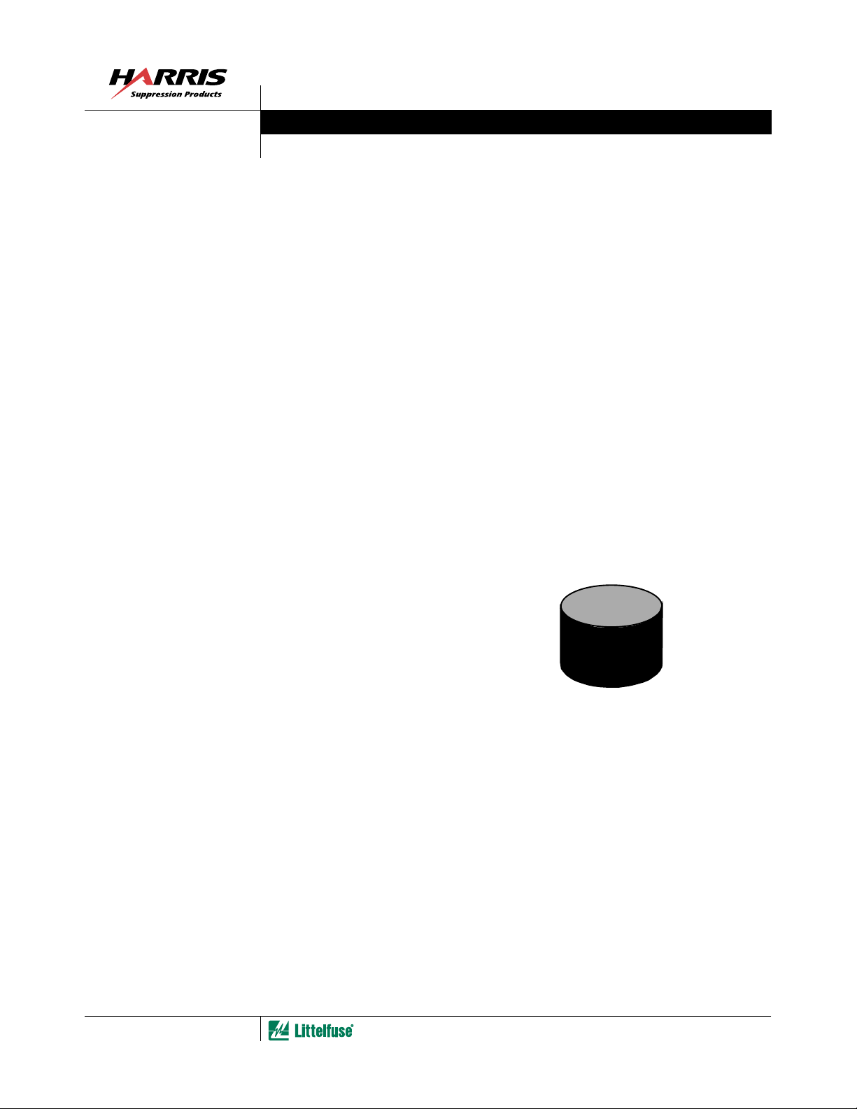
High Energy Metal-Oxide Arrester Blocks
The AS Series of Arrester blocks is primarily designed to be
used as the surge suppression element within a lightning
arrester assembly. These arrester blocks provide the high
peak surge current and energy ratings required for the
protection of high voltage AC power utility distribution
systems. Typically, these devices are placed within a special
arrester housing provided by the customer, and stacked to
achieve the necessary continuous working voltage ratings
for the specific application. (See the CA or NA series of
Varistor discs for lower voltage and energy applications.)
ended
m
ot R
N
For N
Product S
ecom
w
e
een D
B
W
esigns –
D
eries H
iscontin
ith N
as
ued
ent
eplacem
o R
OBSOLETE
File Number 2492.4
Features
• Provided in Disc Form for Unique Packaging by
Customer
• Electrode Finish Enables Pressure Contact for Stacking
Application
• Available Disc Sizes: 32mm, 42mm and 60mm Diameter
• No Follow Current
• High Surge Current Capability
• Conforms to IEC 99-4 and ANSI/IEEE C62.11 Industry
Standards
• Characterized for Lightning Arrester Parameters
Applications
• Lightning Protection of Electrical AC Distribution
Transformers and Systems
• Arrester Assemblies of the Porcelain Polymeric,
“Under-oil” and Metal Clad Variety
Packaging
AS SERIES
PART
8-3
1-800-999-9445 or 1-847-824-1188
|
Copyright
Littelfuse, Inc. 1998
©
µ
AS Series
Absolute Maximum Ratings
Rated Voltage
AC Voltage Range . . . . . . . . . . . . . . . . . . . . . . . . . . . . . . . . . . . . . . . . . . . . . . . . . . . . . . . . . . . . . . . . . 3.00 to 6.00 kV
Steady State Applied Voltage
AC Voltage (MCOV). . . . . . . . . . . . . . . . . . . . . . . . . . . . . . . . . . . . . . . . . . . . . . . . . . . . . . . . . . . . . . . . 2.55 to 5.10 kV
Transient
Peak Pulse Current (I
Energy Rating for 2ms Current Wave . . . . . . . . . . . . . . . . . . . . . . . . . . . . . . . . . . . . . . . . . . . . . . . . . . 2.2 to 12 kJ
Operating Ambient Temperature (T
STORAGE AND HANDLING NOTES:
1. Arrester blocks should be stored in a moisture free environment at all times.
2. Use caution during handling to prevent damage or chipping of edges of the arrester blocks.
CAUTION: Stresses above those listed in “Absolute Maximum Ratings” may cause permanent damage to the device. This is a stress only rating and operation of the
device at these or any other conditions above those indicated in the operational sections of this specification is not implied.
) for 4/10 µ s Current Wave . . . . . . . . . . . . . . . . . . . . . . . . . . . . . . . . . . . . . . . 65 to 100 kA
TM
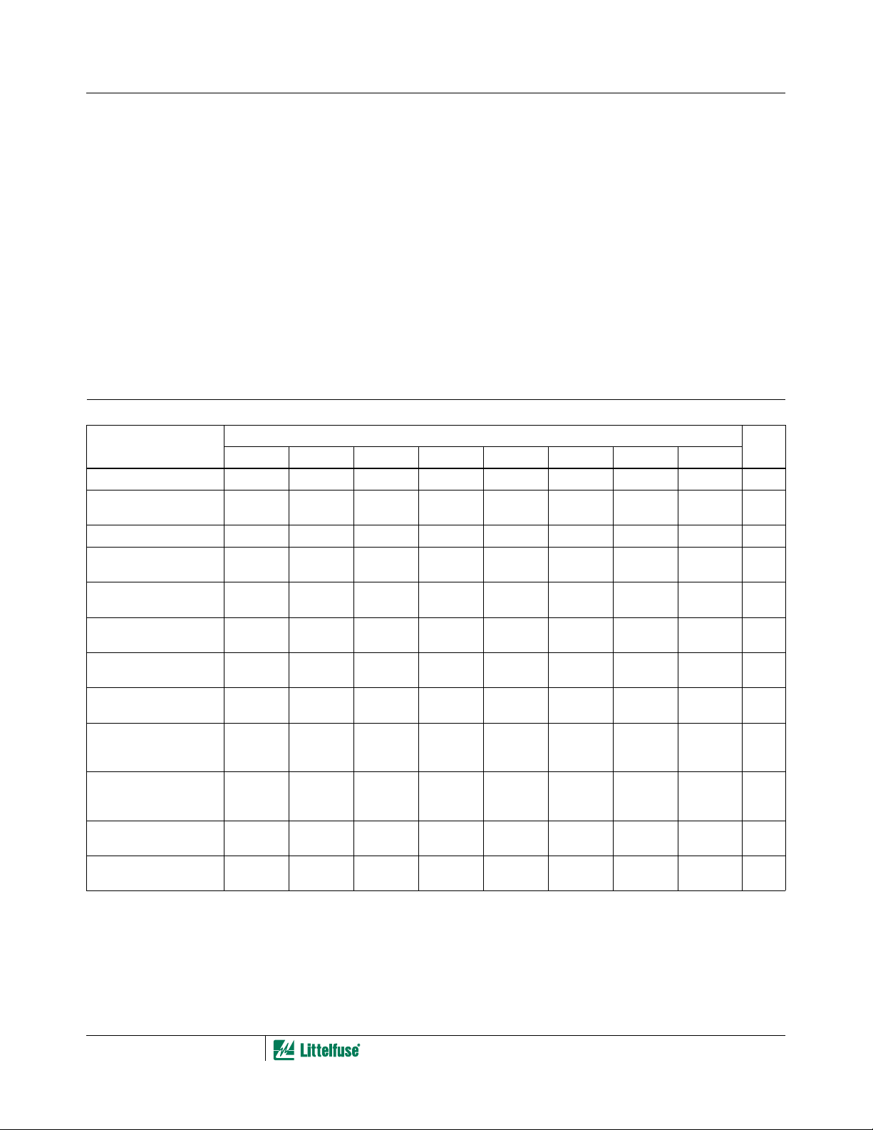
Device Ratings and Specifications
PARAMETER
Rated Voltage (RMS) 3.0 4.0 5.0 6.0 3.0 4.0 5.0 4.0 kV
Maximum Continuous
Operating Voltage (MCOV)
Reference Current, I
Minimum Reference
Voltage, V
Nominal Discharge
Current, I
Residual Voltage (Max) at
I
P
Energy Rating at 60
(2ms)
Peak Current, 4/10 µ s at
60
Maximum Steep Current
Residual Voltage at 5kA
(1/20 µ s)
Maximum Steep Current
Residual Voltage at 10kA
(1/20 µ s)
Maximum Dissipation
Power at MCOV
Maximum Conduction
Current at MCOV
NOTES:
3. In addition to above standard types, custom ratings and dimensions can be provided.
4. Parts should be wrapped using a secondary insulating film or encased by polymeric housing.
P
o
C (Note 4)
REF
(8/20 µ s)
REF
OBSOLETE
o
C
PART
For ratings of individual members of a series, see Device Ratings and Specifications chart
AS SERIES UNITS
) . . . . . . . . . . . . . . . . . . . . . . . . . . . . . . . . . . . . . . . . . . . . . . . . . . . . 60
A
o
25
C Unless Otherwise Specified
PART NUMBER
2.55 3.40 4.25 5.1 2.55 3.40 4.25 3.40 kV
5.0 5.0 5.0 5.0 5.0 5.0 5.0 5.0 mA
3.12 4.16 5.20 6.24 3.12 4.16 5.20 4.16 kV
5.0 5.0 5.0 5.0 10.0 10.0 10.0 10.0 kA
9.8 13.1 16.3 19.6 10.0 13.3 16.7 12.5 kV
2.2 2.9 3.6 4.3 3.5 4.7 5.8 12.0 kJ
65.0 65.0 65.0 65.0 100.0 100.0 100.0 100.0 kA
11.3 15.0 18.8 22.5 - - - - kV
----11.515.319.214.4kV
0.23 0.30 0.38 0.45 0.36 0.48 0.60 0.50 W
75.0 75.0 75.0 75.0 110.0 110.0 110.0 140.0
o
C
UNITSV302AS32 V402AS32 V502AS32 V602AS32 V302AS42 V402AS42 V502AS42 V402AS60
RMS
A
8-4
 Loading...