

LITTELFUSE V9MLN41206WT, V9MLN41206WH, V9MLN41206WA, V5.5MLN41206WT, V5.5MLN41206WH Datasheet
...
3
SURFACE MOUNT
VARISTORS
Surface Mount Varistors
151
www.littelfuse.com
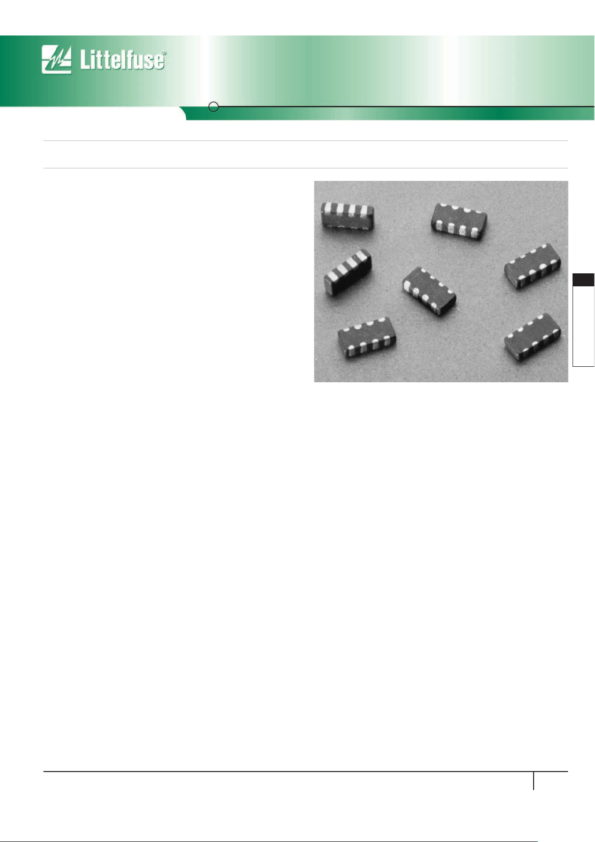
Multiline Transient Voltage Surge Suppressor
MLN SurgeArray™Suppressor
The MLN SurgeArray™Suppressor is designed to help protect components from transient voltages that exist at the circuit board level. This
device provides four independent suppressors in a single “1206” leadless
chip in order to reduce part count and placement time as well as save
space on printed circuit boards.
SurgeArray™devices are intended to suppress ESD, EFT and other
transients in order to protect integrated circuits or other sensitive
components operating at any voltage up to 18VDC. SurgeArray devices
are rated to the IEC 61000-4-2 human body model ESD to help products
attain EMC compliance. The array offers excellent isolation and low
crosstalk between sections.
The inherent capacitance of the SurgeArray Suppressor permits it to
function as a filter/suppressor, thereby replacing separate zener/
capacitor combinations.
The MLN array is manufactured using the Littelfuse Multilayer technology
process and is similar to the Littelfuse ML and MLE Series of discrete
leadless chips.
The MLN can also be provided in a Dual version. Contact Littelfuse
for information.
Features
• Four Individual Devices in One 1206 Chip
• ESD Rated to IEC 61000-4-2 (Level 4)
• AC Characterized for Impedance and Capacitance
• Low Adjacent Channel Crosstalk, -55dB at 10MHz (Typ)
• Low Leakage (6nA at 5.5V, 30nA at 15V)
• Operating Voltage up to 18V
M(DC)
• -55
o
C to 125oC Operating Temperature Range
• Low-Profile, PCMCIA Compatible
Applications
• Data, Diagnostic I/O Ports
• Analog Signal/Sensor Lines
• Portable/Hand-Held Products
• Mobile Communications/Cellular Phones
• Computer/DSP Products
• Industrial Instruments Including Medical
Multiline Transient Voltage Surge Suppressor
MLN SurgeArray™Suppressor
Surface Mount Varistors
152
www.littelfuse.com
Absolute Maximum Ratings
For ratings of individual members of a series, see device ratings and specifications table.
Continuous:
Steady State Applied Voltage: DC Voltage Range (V
M(DC)
). . . . . . . . . . . . . . . . . . . . . . . . . . . . . . . . . . . . . . . . . . . . . . . . . . . 18 V
Operating Ambient Temperature Range (TA) . . . . . . . . . . . . . . . . . . . . . . . . . . . . . . . . . . . . . . . . . . . . . . . . . . . . . . . . . . . . . -55 to 125
O
C
Storage Temperature Range (T
STG
) . . . . . . . . . . . . . . . . . . . . . . . . . . . . . . . . . . . . . . . . . . . . . . . . . . . . . . . . . . . . . . . . . . . -55 to 150
O
C
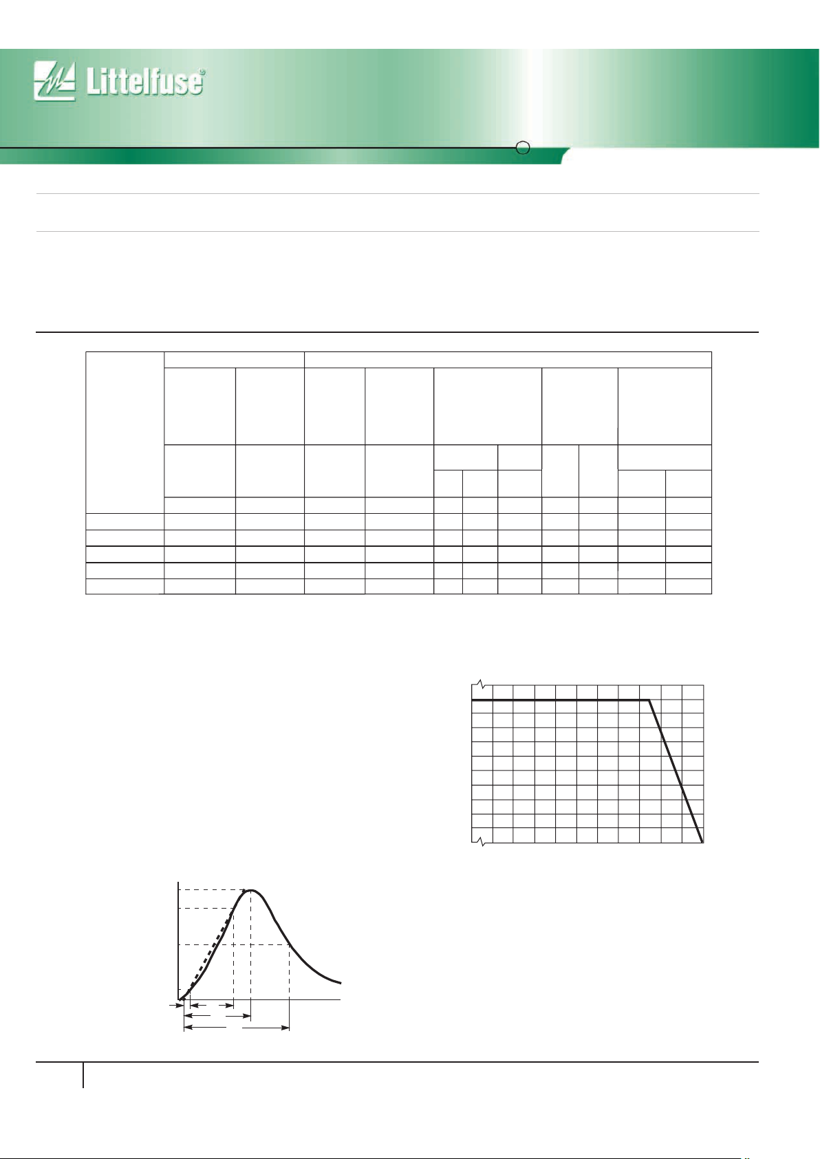
Device Ratings and Specifications Any Single Section
Temperature Derating
For applications exceeding 125oC ambient temperature, the peak surge
current and energy ratings must be reduced as shown in Figure 1.
MLN ARRAY UNITS
PA RT
NUMBER
MAX RATINGS (125
o
C) PERFORMANCE SPECIFICATIONS (25oC)
MAXIMUM
CONTINUOUS
WORKING
VO LTAGE
MAXIMUM
NON-
REPETITIVE
SURGE
CURRENT
(8/20µs)
MAXIMUM
CLAMPING
VO LTAGE
(AT NOTED
CURRENT
8/20µs)
MAXIMUM
NON-
REPETITIVE
SURGE
ENERGY
(10/1000µs)
TYPICAL
ESD SUPPRESSION
VOLTAGE (NOTE 1)
NOMINAL
VO LTAGE AT
1mA DC
CURRENT
CAPACITANCE
AT
1MHz (1V p-p)
V
M(DC)
I
TM
V
C
W
TM
(V) (A) (V) (J) (V) (V) (pF)
V5.5MLN41206
V9MLN41206
V14MLN41206
V18MLN41206
V18MLN41206L
430 520
250 300
140 175
100 125
NOTES:
1. Tested to IEC61000-4-2 Human Body Model (HBM) discharge test circuit. See explanation of Terms on page 7.
2. Direct discharge to device terminals (IEC preffered test method). See figure 2.
3. Corona discharge through air (represents actual ESD event)
4. Capacitance may be customized, contact Sales.
(See Fig. 3)
Peak
(NOTE 2)
8kV CONTACT
(NOTE 3)
15kV AIR
Clamp
(V)
Peak
(V)
(V)
VN(DC)
MIN
V
N(DC)
MAX
(NOTE 4)
C
TYP MAX
(pF)
45 75
5.5
9
14
18
18
30
30
30
30
20
7.1
11.0
15.9
22.0
25.0
9.3
16.0
20.3
28.0
35.0
60
95
110
165
200
35
50
55
60
95
45
75
85
100
130
0.1
0.1
0.1
0.1
0.05
15.5 at 2A
23 at 2A
30 at 2A
40 at 2A
50 at 1A
100
90
80
70
60
50
40
30
20
10
0
-55 50 60 70 80 90 100 110 120 130 140 150
PERCENT OF RATED VALUE
AMBIENT TEMPERATURE (oC)
FIGURE 1. PEAK CURRENT AND ENERGY DERATING CURVE
t
t
1
t
2
100
90
50
10
O
1 TIME
PERCENT OF PEAK VALUE
O1 = VIRTUAL ORIGIN OF WAVE
t
1
= VIRTUAL FRONT TIME = 1.25 x t
(IMPULSE DURATION)
t = TIME FROM 10% TO 90% OF PEAK
t
2
= VIRTUAL TIME TO HALF VALUE
EXAMPLE:
FOR AN 8/20µs CURRENT
WAVEFORM:
8µs = t
1
= VIRTUAL FRONT
20µs = t
2
= VIRTUAL TIME TO
HALF VALUE
TIME
FIGURE 2. PEAK PULSE CURRENT TEST WAVEFORM FOR CLAMPING VOLTAGE
Typical Performance Curves Any Single Section
40
30
20
10
0
1 10 100 1000
NUMBER OF DISCHARGES
V
NOM
10,000
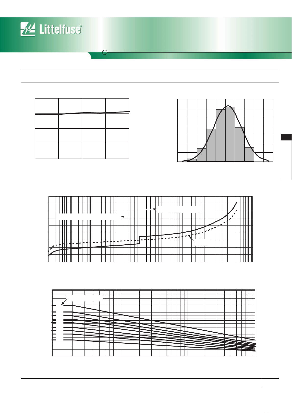
FIGURE 4. PRODUCT DISTRIBUTION OF CAPACITANCE (1MHz)
70
60
50
40
30
20
10
0
SAMPLES
CAPACITANCE (pF)
7060504030 35 45 55 65
Typical Performance Curves Any Single Section
FIGURE 5. V-I CHARACTERISTICS
FIGURE 6. PULSE RATING FOR LONG DURATION SURGES (ANY SINGLE SECTION)
90
80
70
60
50
40
30
20
10
0
VARISTOR VOLTAGE (V)
1.0E
-07
CURRENT (A)
1.0E
-06
1.0E
-05
1.0E
-04
1.0E
-03
1.0E
-02
1.0E
-01
1.0E
+00
1.0E
+01
1.0E
+02
MAXIMUM STANDBY CURRENT (LEAKAGE)
MAXIMUM CLAMP VOLTAGE
TYPICAL
1
2
10
100
10
3
10
4
10
5
10
6
∞
100
10
1
0.1
10 100 1000 10000
SQUARE WAVE PULSE DURATION ( µs)
SURGE CURRENT (A)
NUMBER OF SURGES
MLN SurgeArray™Suppressor
Surface Mount Varistors
Multiline Transient Voltage Surge Suppressor
153
www.littelfuse.com
3
SURFACE MOUNT
VARISTORS
 Loading...