

LITTELFUSE V18MLE1206H, V18MLE1206A, V18MLE0805WT, V18MLE0805WH, V18MLE0805WA Datasheet
...
3
SURFACE MOUNT
VARISTORS
Surface Mount Varistors
133
www.littelfuse.com
Multilayer Transient Voltage Suppressor
MLE Varistor Series
The MLE Series family of Transient Voltage Suppression devices are based
on the Littelfuse Multilayer fabrication technology. These components are
designed to suppress ESD events, including those specified in IEC 610004-2 or other standards used for Electromagnetic Compliance testing. The
MLE Series is typically applied to protect integrated circuits and other
components at the circuit board level operating at 18VDC, or less.
The fabrication method and materials of these devices result in capacitance characteristics suitable for high frequency attenuation/low-pass
filter circuit functions, thereby providing suppression and filtering in a
single device.
The MLE Series is manufactured from semiconducting ceramics and is supplied in a leadless, surface mount package.The MLE Series is compatible
with modern reflow and wave soldering procedures.
Littelfuse Inc. manufactures other Multilayer Series products. See the ML
Series data sheet for higher energy/peak current transient applications. See
the AUML Series for automotive applications and the MLN Quad Array. For
high speed applications see the MHS series.
Features
• Rated for ESD (IEC-61000-4-2)
• Characterized for Impedance and Capacitance
•-55
o
C to +125oC Operating Temperature Range
• Leadless 0402, 0603, 0805, and 1206 sizes
• Operating Voltages up to 18V
M(DC)
• Multilayer Ceramic Construction Technology
Applications
• Protection of Components and Circuits Sensitive to ESD Transients
Occurring on Power Supplies, Control and Signal Lines
• Suppression of ESD Events Such as Specified in IEC-61000-4-2 or
MIL-STD-883C Method-3015.7, for Electromagnetic Compliance (EMC)
• Used in Mobile Communications, Computer/EDP Products, Medical
Products, Hand Held/Portable Devices, Industrial Equipment,
Including Diagnostic Port Protection and I/O Interfaces

Multilayer Transient Voltage Suppressor
MLE Varistor Series
Surface Mount Varistors
134
www.littelfuse.com
Absolute Maximum Ratings
For ratings of individual members of a series, see device ratings and specifications table.
Continuous:
Steady State Applied Voltage:
DC Voltage Range (V
M(DC)
) . . . . . . . . . . . . . . . . . . . . . . . . . . . . . . . . . . . . . . . . . . . . . . . . . . . . . . . . . . . . . . . . . . . . . . . . . . ≤18 V
Operating Ambient Temperature Range (TA) . . . . . . . . . . . . . . . . . . . . . . . . . . . . . . . . . . . . . . . . . . . . . . . . . . . . . . . . . . . . . . -55 to + 125
O
C
Storage Temperature Range (T
STG
). . . . . . . . . . . . . . . . . . . . . . . . . . . . . . . . . . . . . . . . . . . . . . . . . . . . . . . . . . . . . . . . . . . . -55 to + 150
O
C
Device Ratings and Specifications
PA RT
NUMBER
MAX CONTINUOUS
WORKING VOLTAGE
-55
o
C TO 125oC
PERFORMANCE SPECIFICATIONS (25
o
C)
NOMINAL
VO LTAGE
TYPICAL
CAPACITANCE
AT 1MHz
MAXIMUM
LEAKAGE
(NOTE 1)
V
M(DC)
V
NOM
AT
1mA DC I
L MAX
AT APPLIED
VO LTAGE
(V) MIN (V)
MAX
(V)
(NOTE 3)
8kV CONTACT
Clamp
(V)
(NOTE 4)
15kV AIR
( pF) ( µA) V
DC
V18MLE0603L 18 22 28 50
at 10A
<60 0.1 3.5
0.3 5.5
5.0 15
25 18
V18MLE0805 18 22 28 50
at 10A
<500 0.2 3.5
0.5 5.5
5.0 15
25 18
V18MLE0805L 18 22 28 50
at 10A
<100 0.2 3.5
0.5 5.5
5.0 15
25 18
V18MLE1206 18 22 28 50
at 10A
<1700 0.5 3.5
1.0 5.5
5.0 15
25 18
NOTES:
1. For applications of 18V
DC
or less. Higher voltages available, contact your Littelfuse Sales Representative.
2. Tested with IEC-61000-4-2 Human Body Model (HBM) discharge test circuit.
3. Direct discharge to device terminals (IEC preferred test method).
4. Corona discharge through air (represents actual ESD event).
5. Capacitance may be customized, contact your Littelfuse Sales Representative.
V18MLE0603 18 22 28 50
at 10A
<100 0.1 3.5
0.3 5.5
5.0 15
25 18
V18MLE0402 18 22 28 50
at 10A
<140
<75
<135
<65
<85
<160 <40 0.1 3.5
0.3 5.5
215
10 18
MAXIMUM
ESD CLAMP VOLTAGE (NOTE 2)
Clamp
(V)
MAXIMUM CLAMPING
VOLTAGE AT SPECIFIED
CURRENT (8/20µS)
(V)
Vc
<100
<70
<75
<65
<75
<125
NEW
MLE SERIES UNITS
MLE Varistor Series
Surface Mount Varistors
Multilayer Transient Voltage Suppressor
135
www.littelfuse.com
3
SURFACE MOUNT
VARISTORS
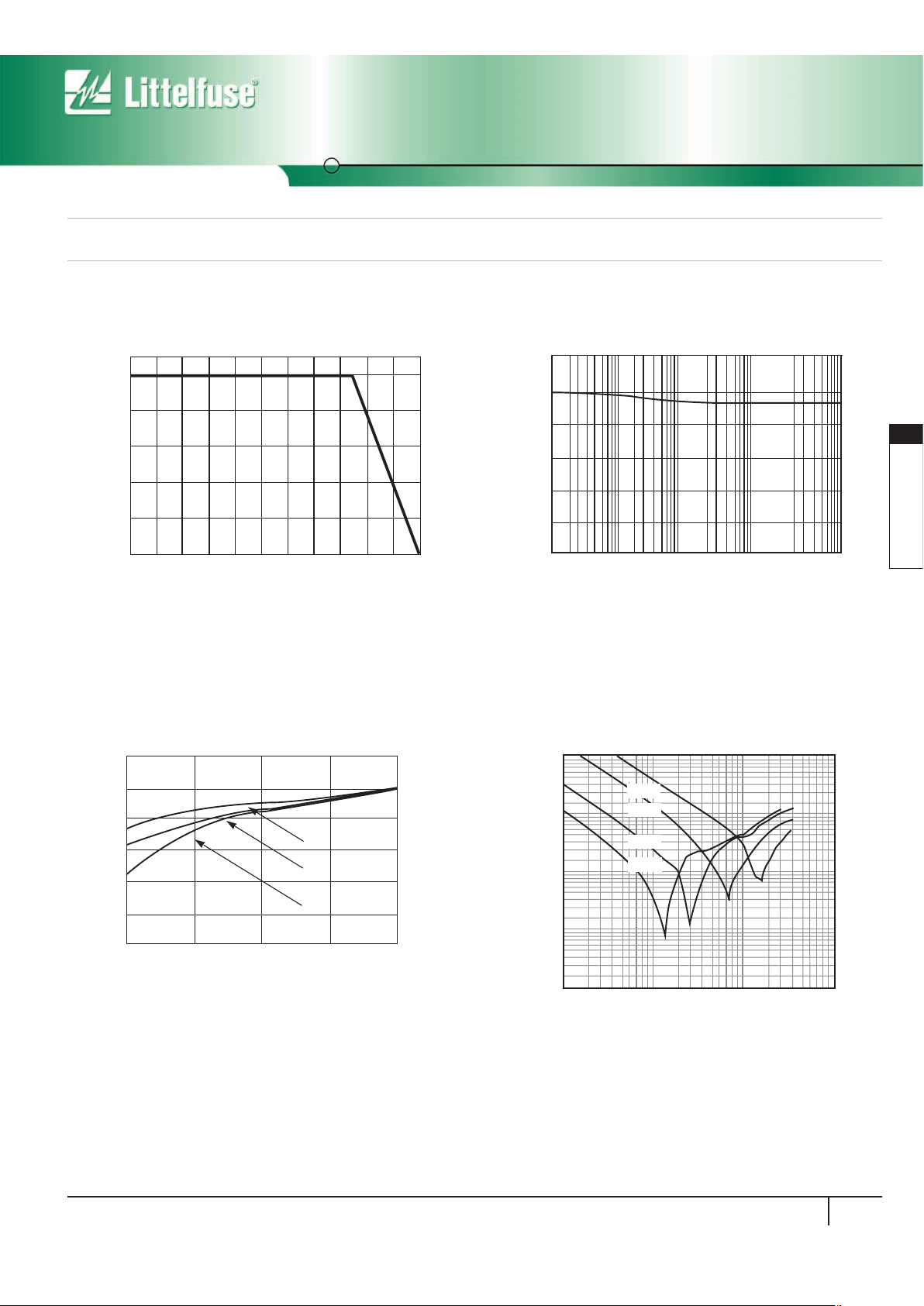
FIGURE
4. IMPEDANCE (Z) vs FREQUENCY
TYPICAL CHARACTERISTIC
0.1
FREQUENCY (MHz)
IMPEDANCE (Z)
10
100
1000
10000
1
10
100
0.01
-0402
-0603
-0805
-1206
Typical Performance Curves
For applications exceeding 1250C ambient temperature, the peak surge
current and energy ratings must be reduced as shown in Figure 1.
30
10
0.0001250.001 0.01 0.1 1
NUMBER OF PULSES
VARISTOR VOLTAGE (V)
FIGURE 3. STANDBY CURRENT AT NORMALIZED VARISTOR
VOLTAGE AND TEMPERATURE
25
20
15
10
5
85
125
O
O
O
100
80
60
40
20
0
-55 50 60 70 80 90 100 110 120 130 140 150
PERCENT OF RATED VALUE
AMBIENT TEMPERATURE (oC)
FIGURE 1. PEAK CURRENT AND ENERGY DERATING CURVE
FIGURE 2. NOMINAL VOLTAGE STABILITY TO MULTIPLE
ESD IMPULSES (8KV CONTACT DISCHARGES
PER IEC 61000-4-2)
25
0
1
CURRENT (A)
NOMINAL VOLTAGE AT 1mADC
10
100
1000
10000
5
10
15
20
30
 Loading...