

LITTELFUSE V8CP22, V38CP16, V38CP22, V38CP20, V31CP22 Datasheet
...
CP Series
[ /Title
(CP
Series)
/Subject
(Tubular
MetalOxide
Varistors)
/Autho
r ()
/Keywords
(Littelfuse,
Inc.,
Suppression
Products,
TVS,
Transient
Suppression,
Protection,
Highreliability,
High
Reliability,
Mil,
Hi-rel,
Data Sheet July 1999
Tubular Metal-Oxide Varistors
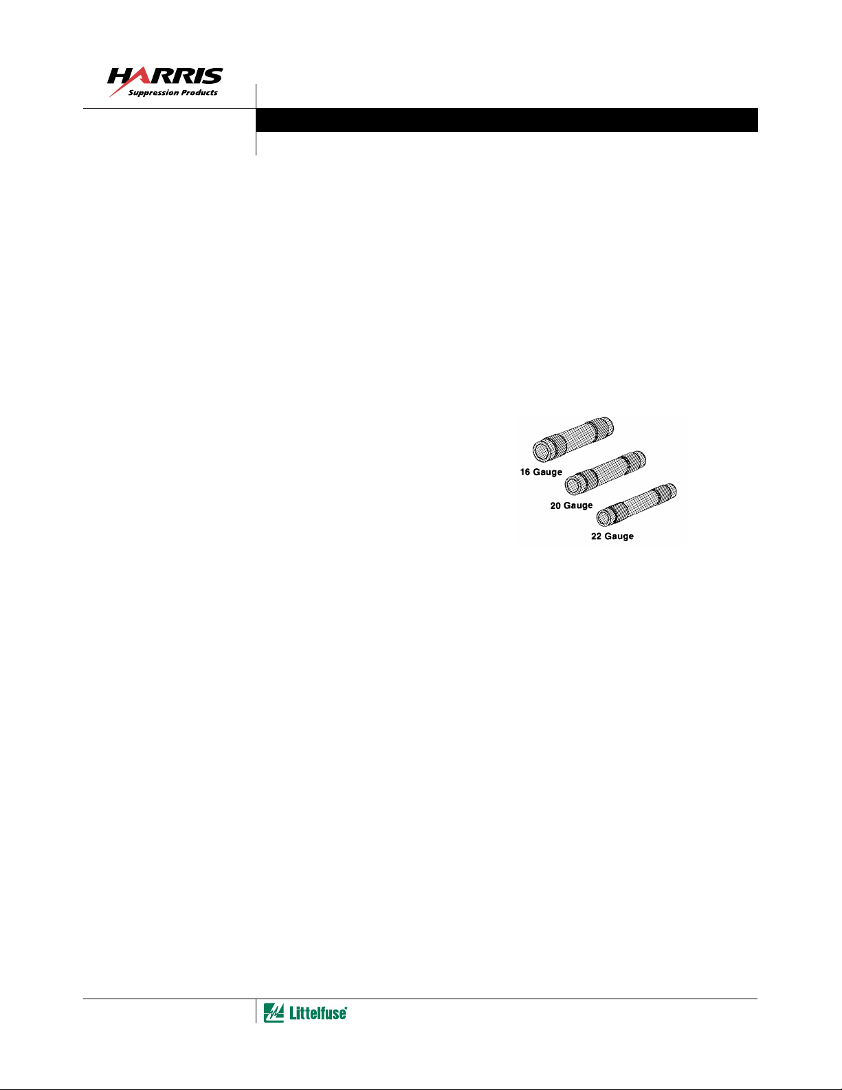
The CP Series of transient voltage surge suppressors are
metal-oxide varistors (MOVs) of tubular construction. These
varistors are intended for mounting within a multipin
connector assembly. This series is available in a wide range
of voltage ratings from 6V to 150V V
dimensions allow them to be used with 16, 20, or 22 gauge
connector pins. The unique coaxial mounting arrangement of
these tubular varistors allow them to become part of a
transmission line itself. Added inductive lead effects are
eliminated.
Varistor action takes place between the inside and outside
diameters of the tube. Typically, data or signal lines make
electrical connection to the inside of the tube. The outside
tube surface is then connected to ground or common.
The CP Series is supplied in Bulk Pack.
M(AC)RMS
. Their internal
Features
• Unique Coaxial Design and Mounting Arrangement in
Tubular Form
• Designed to be Integrated Within Standard Connector
Assemblies
• Wide Operating Voltage Range V
• Can be Used with 16, 20, or 22 Gauge Standard
Connector Pins
• No Derating up to 125
Packaging
OBSOLETE
PART
File Number 2188.5
o
C Ambient
CP SERIES
M(AC)RMS
. . . . 6V to 150V
4-82
1-800-999-9445 or 1-847-824-1188
|
Copyright
Littelfuse, Inc. 1999
©
CP Series
Absolute Maximum Ratings
Continuous:
Steady State Applied Voltage:
AC Voltage Range (V
DC Voltage Range (V
Transient:
Peak Pulse Current (I
For 8/20 µ s Current Wave (See Figure 2) . . . . . . . . . . . . . . . . . . . . . . . . . . . . . . . . . . . . . . . . . . . . . . . .
Single Pulse Energy Range
For 10/1000 µ s Current Wave (W
Operating Ambient Temperature Range (T
Storage Temperature Range (T
Temperature Coefficient ( α V) of Clamping Voltage (V
CAUTION: Stresses above those listed in “Absolute Maximum Ratings” may cause permanent damage to the device. This is a stress only rating and operation of the
device at these or any other conditions above those indicated in the operational sections of this specification is not implied.
M(AC)RMS
) . . . . . . . . . . . . . . . . . . . . . . . . . . . . . . . . . . . . . . . . . . . . . . . . . . . . . . . . .
M(DC)
)
TM
For ratings of individual members of a series, see Device Ratings and Specifications chart
CP SERIES UNITS
) . . . . . . . . . . . . . . . . . . . . . . . . . . . . . . . . . . . . . . . . . . . . . . . . . . . . . .
250 to 500
) . . . . . . . . . . . . . . . . . . . . . . . . . . . . . . . . . . . . . . . . . . . . . . . . . . .
TM
) . . . . . . . . . . . . . . . . . . . . . . . . . . . . . . . . . . . . . . . . . . . . . . . -55 to 125
A
) . . . . . . . . . . . . . . . . . . . . . . . . . . . . . . . . . . . . . . . . . . . . . . . . . . . . . -55 to 150
STG
) at Specified Test Current . . . . . . . . . . . . . . . . . . <0.01 %/
C
6 to 150
8 to 150
1.5 to 5
V
V
A
J
o
C
o
C
o
C
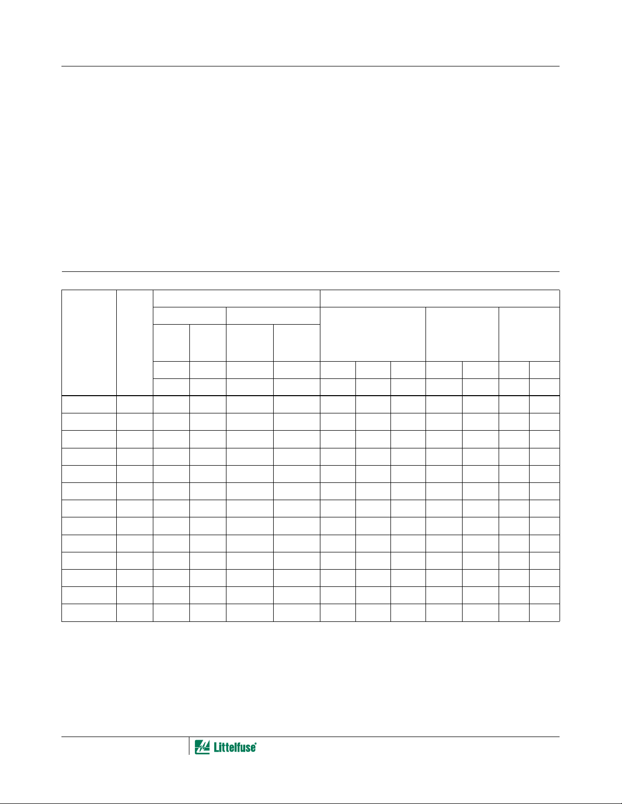
Device Ratings and Specifications
MODEL
NUMBER
TM
o
C) SPECIFICATIONS (25
MAX. CLAMPING
PEAK
CURRENT
(8/20 µ s)
I
TM
VARISTOR VOLTAGE AT
1mA DC TEST CURRENT
MIN V
N(DC)
MAX V
VOLTAGE V
TEST CURRENT
MAXIMUM RATINGS (125
CONTINUOUS TRANSIENT
DC
ENERGY
(10/1000 µ s)
W
RMS
OBSOLETE
PART
SIZE
V
M(AC)
(V) (V) (J) (A) (V) (V) (V) (V) (A) (pF) (pF)
V
V
M(DC)
(8/20 µ s)
C
o
C)
C
I
AT
P
CAPACI-
TANCE AT
f = 1MHzV
MIN MAX
V8CP22 22B 6.0 8.0 1.5 250 12.5 16.0 19.5 34.0 10 1600 2950
V14CP22 22B 10.0 14.0 1.5 250 18.5 22.0 25.5 42.0 10 1600 2950
V31CP22 22B 25.0 31.0 1.5 250 35.0 39.0 48.0 85.0 5 450 1950
V38CP22 22B 30.0 38.0 1.5 250 42.0 47.0 58.0 100.0 5 450 1950
V130CP22 22A 130.0 130.0 2.4 300 184.0 200.0 228.0 375.0 5 150 350
V150CP22 22A 150.0 150.0 2.4 300 212.0 240.0 268.0 430.0 5 100 300
V31CP20 20B 25.0 31.0 2.0 300 35.0 39.0 48.0 85.0 10 700 2200
V38CP20 20B 30.0 38.0 2.0 300 42.0 47.0 58.0 100.0 10 650 1950
V130CP20 20A 130.0 130.0 3.0 400 184.0 200.0 228.0 375.0 10 150 400
V150CP20 20A 150.0 150.0 3.0 400 212.0 240.0 268.0 430.0 10 100 350
V38CP16 16A 30.0 38.0 3.0 350 42.0 47.0 58.0 100.0 20 1000 2750
V130CP16 16A 130.0 130.0 5.0 500 184.0 200.0 228.0 375.0 20 250 700
V150CP16 16A 150.0 150.0 5.0 500 212.0 240.0 268.0 430.0 20 200 650
NOTE: Average power dissipation of transients not to exceed 250mW, 300mW and 350mW for sizes 22AWG, 20AWG and 16AWG, respectively.
PART
4-83
 Loading...