

Page 1
UltraMOV™Varistor Series
®
V
DE
®
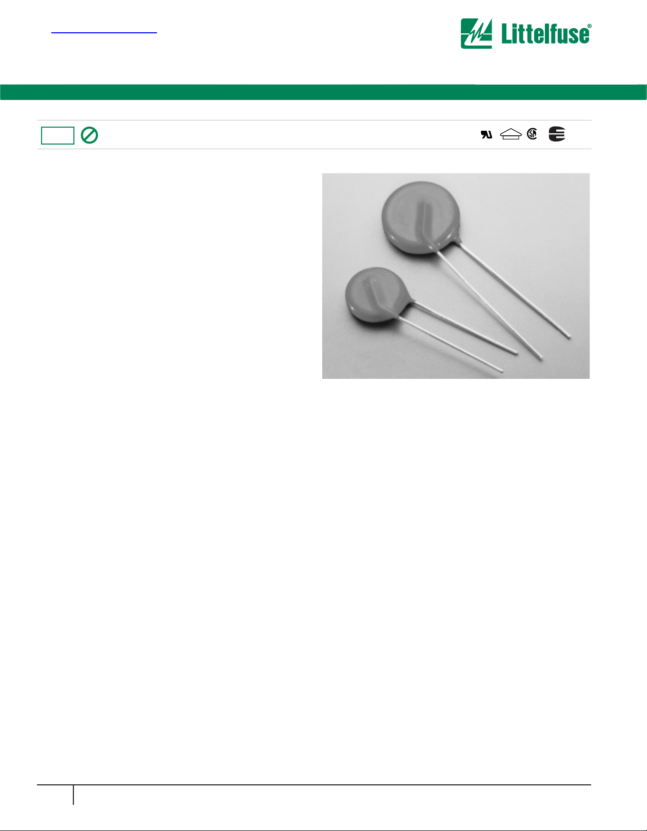
The UltraMOV Metal Oxide Varistor Series is designed for applications
requiring high peak surge current ratings and high energy absorption
capability. UltraMOV varistors are primarily intended for use in AC Line
Voltage applications such as Transient Voltage Surge Suppressors
(TVSS), Uninterruptable Power Supplies (UPS), AC Power Taps, AC
Power Meters, or other products that require voltage clamping of high
transient surge currents from sources such as lightning, inductive load
switching, or capacitor bank switching.
These devices are produced in radial lead package sizes of 7, 10, 14,
and 20mm and offered in a variety of lead forms.UltraMOVs are
manufactured with recognized epoxy encapsulation and are rated for
ambient temperatures up to 85
o
C with no derating.This Series is
LASER-branded and is supplied in bulk, ammo pack (fan-fold), or tape
and reel packaging.
Features
• Lead-free and RoHS compliant option available. Please see the
device and ratings specifications table for more information.
• High Peak Surge Current Rating (ITM) Up to 10kA, Single 8 x 20
Pulse, (20mm)
• Standard Operating Voltage Range Compatible with Common AC
Line Voltages (130VAC to 625VAC)
• Characterized for Maximum Standby Current (Leakage)
• Custom Voltage Types Available
• Standard Lead Form and Lead Space Options
AGENCY APPRO VALS: Recognized under the components program of
Underwriters Laboratories. Certified by CSA, VDE and CECC.VDE certification of Lead-free and RoHS compliant parts pending.
AGENCY FILE NUMBERS: UL E75961, CSA LR91788,
VDE 116895E, CECC 42201-006.
36
www.littelfuse.com
Varistor Products
High Surge Current, Radial Lead
Pb
RoHS
NEW LEAD-FREE AND
RoHS COMPLIANT PARTS
AVAILABLE
查询V07E130供应商
Page 2
37
www.littelfuse.com
Varistor Products
High Surge Current, Radial Lead
Absolute Maximum Ratings For ratings of individual members of a series, see Device Ratings and Specifications chart
Continuous:
Steady State AC Voltage Range (V
M(AC)RMS
) . . . . . . . . . . . . . . . . . . . . . . . . . . . . . . . . . . . . . . . . . . . . . . . . . . . . . . . . . 130 to 625V V
Transient:
Single-Pulse Peak Current (ITM) 8x20µs Wave (See Figure 2) . . . . . . . . . . . . . . . . . . . . . . . . . . . . . . . . . . . . . . . . . . . . 1,750 to 10,000 A
Single-Pulse Energy Range (WTM) 2ms Square Wave . . . . . . . . . . . . . . . . . . . . . . . . . . . . . . . . . . . . . . . . . . . . . . . . . . . 12.5 to 400 J
Maximum Temporary Overvoltage of V
M(AC)
5 Minutes at 25oC . . . . . . . . . . . . . . . . . . . . . . . . . . . . . . . . . . . . . . . . . . . . . . . . . . . . . . . . . . . . . . . . . . . . . . . . . . . . . . . . . . . . 130 %
5 Minutes at 125oC . . . . . . . . . . . . . . . . . . . . . . . . . . . . . . . . . . . . . . . . . . . . . . . . . . . . . . . . . . . . . . . . . . . . . . . . . . . . . . . . . . . 125 %
Operating Ambient Temperature Range (TA) . . . . . . . . . . . . . . . . . . . . . . . . . . . . . . . . . . . . . . . . . . . . . . . . . . . . . . . . . . . . . . . -55 to 85
o
C
Storage Temperature Range (T
STG
) . . . . . . . . . . . . . . . . . . . . . . . . . . . . . . . . . . . . . . . . . . . . . . . . . . . . . . . . . . . . . . . . . . . . . -55 to125
o
C
Temperature Coefficient (V) of Clamping Voltage (VC) at Specified Test Current . . . . . . . . . . . . . . . . . . . . . . . . . . . . . . . . . . . . <0.01 %/oC
Hi-Pot Encapsulation Isolation Voltage Capability, Per MIL-STD-202, Method 301 . . . . . . . . . . . . . . . . . . . . . . . . . . . . . . . . . . . . 2500 V
CAUTION:Stresses above those listed in “Absolute Maximum Ratings” may cause permanent damage to the device. This is a stress only rating and operation of the device
at these or any other conditions above those indicated in the operational sections of this specification is not implied.
NOTE: 2MS SQ Wave Us.100x1000 exponential condition for Ultra CIII, LA, TA and FCTC.
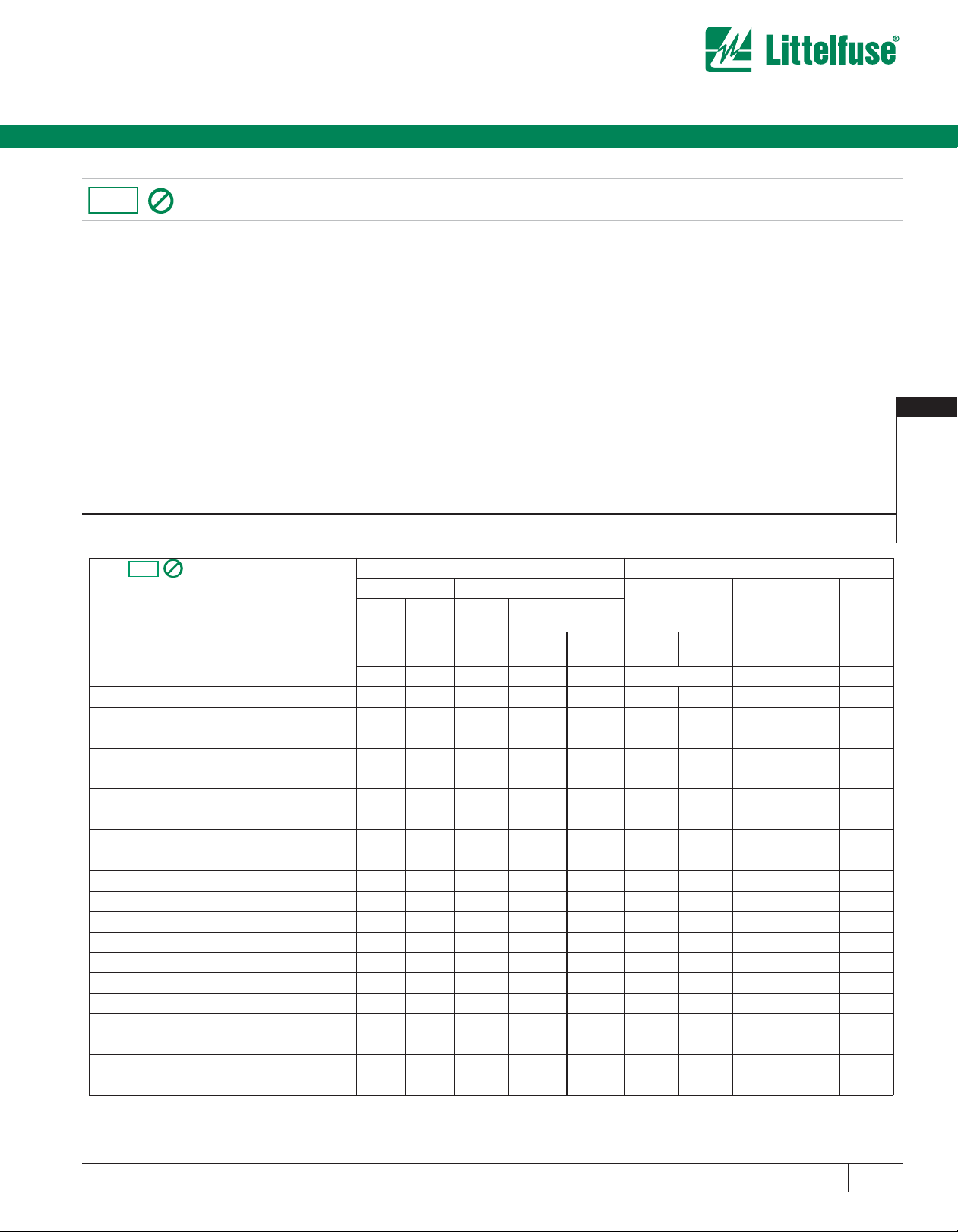
UL TRAMO V V ARIST OR
UNITS
MAXIMUM RATING (85oC) SPECIFICATIONS (25oC)
CONTINUOUS TRANSIENT
VARISTOR
VOLTAGE AT 1mA
DC TEST CURRENT
MAXIMUM
CLAMPING
VOLTAGE 8 x 20 µs
TYPICAL
CAPACI-
TANCE
RMS
VOLTSDCVOLTS
ENERGY
2ms
PEAK CURRENT
8x20µs
V
M(AC)VM(DC)
W
TM
V
NOM
MIN
V
NOM
MAX V
C
I
PK
f = 1MHz
(V) (V) (J) (V) (V) (A) (pF)
V07E130 7V130 130 170 12.5 184 226 340 10 180
V10E130 10V130 130 170 25 184 226 340 25 450
V14E130 14V130 130 170 50 184 226 340 50 1000
V20E130 20V130 130 170 100 184 226 340 100 1900
V07E140 7V140 140 180 13.5 200 240 360 10 160
V10E140 10V140 140 180 27.5 200 240 360 25 400
V14E140 14V140 140 180 55 200 240 360 50 900
V20E140 20V140 140 180 110 200 240 360 100 1750
V07E150 7V150 150 200 15 216 264 395 10 150
V10E150 10V150 150 200 30 216 264 395 25 360
V14E150 14V150 150 200 60 216 264 395 50 800
V20E150 20V150 150 200 120 216 264 395 100 1600
V07E175 7V175 175 225 17 243 297 455 10 130
V10E175 10V175 175 225 35 243 297 455 25 350
V14E175 14V175 175 225 70 243 297 455 50 700
V20E175 20V175 175 225 135 243 297 455 100 1400
V07E230 7V230 230 300 20 324 396 595 10 100
V10E230 10V230 230 300 42 324 396 595 25 250
V14E230 14V230 230 300 80 324 396 595 50 550
V20E230 20V230 230 300 160
I
TM
1 x PULSE
(A)
1750
3500
6000
10000
1750
3500
6000
10000
1750
3500
6000
10000
1750
3500
6000
10000
1750
3500
6000
10000 324 396 595 100 1100
I
TM
2 x PULSE
(A)
1200
2500
4500
6500
1200
2500
4500
6500
1200
2500
4500
6500
1200
2500
4500
6500
1200
2500
4500
6500
PA RT
NUMBER
BRANDING
V07E130P P7V130
V10E130P P10V130
V14E130P P14V130
V20E130P P20V130
V07E140P P7V140
V10E140P P10V140
V14E140P P14V140
V20E140P P20V140
V07E150P P7V150
V10E150P P10V150
V14E150P P14V150
V20E150P P20V150
V07E175P P7V175
V10E175P P10V175
V14E175P P14V175
V20E175P P20V175
V07E230P P7V230
V10E230P P10V230
V14E230P P14V230
V20E230P P20V230
BRANDING
LEAD-FREE
AND RoHS
COMPLIANT
MODELS
STANDARD
MODELS
Pb
RoHS
PA RT
NUMBER
Device Ratings and Specifications
2
VARISTOR
PRODUCTS
VARISTOR
PRODUCTS
UltraMOV™Varistor Series
Pb
RoHS
Page 3
38
www.littelfuse.com
Varistor Products
High Surge Current, Radial Lead
UltraMOV™Varistor Series
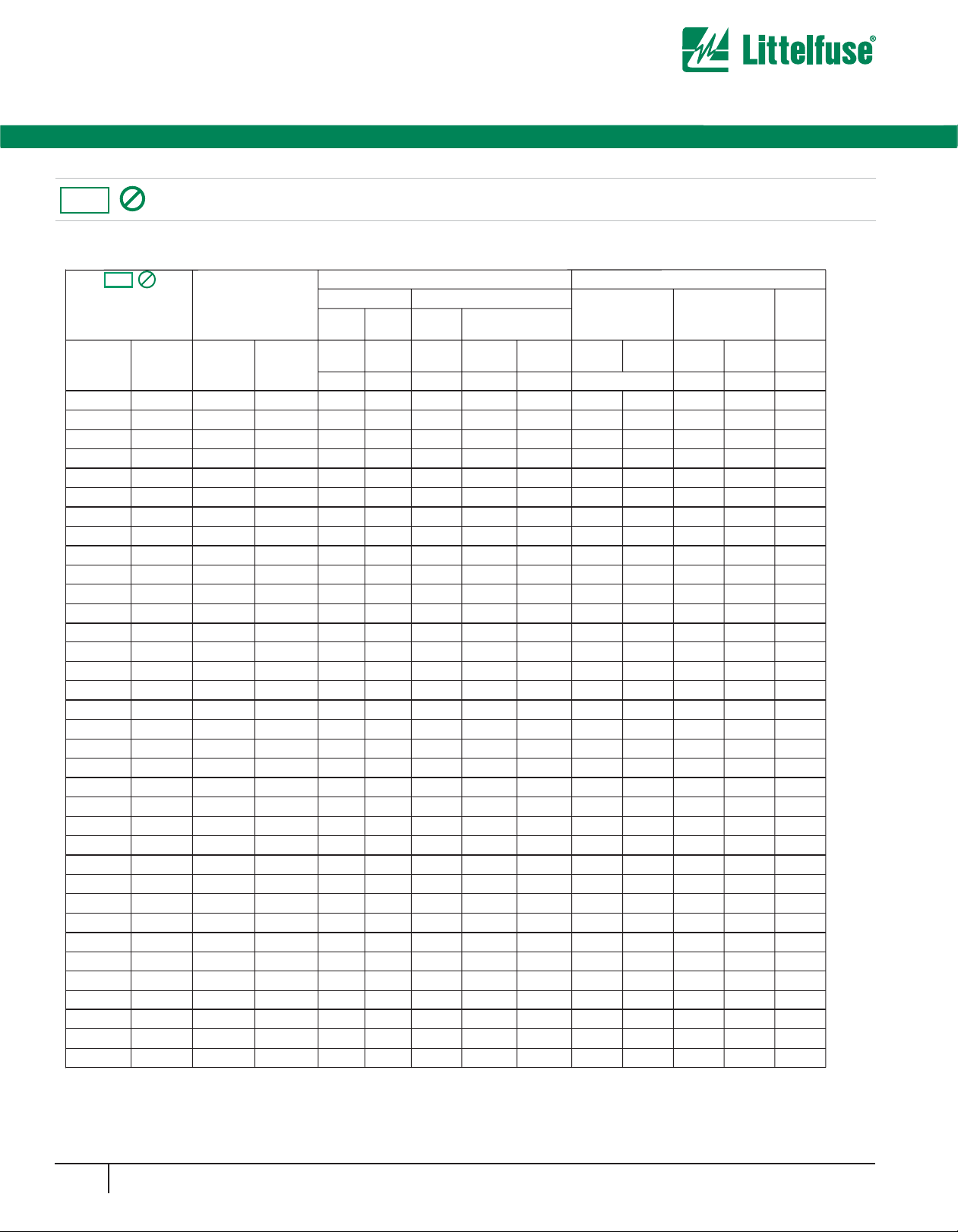
Device Ratings and Specifications (Continued)
V07E250 7V250 250 320 25 351 429 650 10 90
V10E250 10V250 250 320 50 351 429 650 25 220
V14E250 14V250 250 320 100 351 429 650 50 500
V20E250 20V250 250 320 170 351 429 650 100 1000
V07E275 7V275 275 350 28 387 473 710 10 80
V10E275 10V275 275 350 55 387 473 710 25 200
V14E275 14V275 275 350 110 387 473 710 50 450
V20E275 20V275 275 350 190 387 473 710 100 900
V07E300 7V300 300 385 30 423 517 775 10 70
V10E300 10V300 300 385 60 423 517 775 25 180
V14E300 14V300 300 385 125 423 517 775 50 400
V20E300 20V300 300 385 250 423 517 775 100 800
V07E320 7V320 320 420 32 459 561 840 10 65
V10E320 10V320 320 420 67 459 561 840 25 170
V14E320 14V320 320 420 136 459 561 840 50 380
V20E320 20V320 320 420 273 459 561 840 100 750
V07E385 7V385 385 505 36 558 682 1025 10 60
V10E385 10V385 385 505 75 558 682 1025 25 160
V14E385 14V385 385 505 150 558 682 1025 50 360
V20E385 20V385 385 505 300 558 682 1025 100 700
V07E420 7V420 420 560 40 612 748 1120 10 55
V10E420 10V420 420 560 80 612 748 1120 25 140
V14E420 14V420 420 560 160 612 748 1120 50 300
V20E420 20V420 420 560 320 612 748 1120 100 600
V07E440 7V440 440 585 44 643 787 1180 10 50
V10E440 10V440 440 585 85 643 787 1180 25 130
V14E440 14V440 440 585 170 643 787 1180 50 260
V20E440 20V440 440 585 340 643 787 1180 100 500
V07E460 7V460 460 615 48 675 825 1240 10 45
V10E460 10V460 460 615 90 675 825 1240 25 120
V14E460 14V460 460 615 180 675 825 1240 50 220
V20E460 20V460 460 615 360 675 825 1240 100 400
V10E510 10V510 510 670 80 738 902 1355 25 110
V14E510 14V510 510 670 165 738 902 1355 50 200
V20E510 20V510 510 670 325 738 902 1355 100 350
BRANDING
MAXIMUM RATING (85
o
C) SPECIFICATIONS (25oC)
CONTINUOUS TRANSIENT
VARISTOR
VOLTAGE AT 1mA
DC TEST CURRENT
MAXIMUM
CLAMPING
VOLTAGE 8 x 20 µs
TYPICAL
CAPACI-
TANCE
RMS
VOLTS
DC
VOLTS
ENERGY
2ms
PEAK CURRENT
8 x 20µs
V
M(AC)VM(DC)
W
TM
V
NOM
MIN
V
NOM
MAX V
C
I
PK
f = 1MHz
(V) (V) (J)
I
TM
1 x PULSE
(A)
1750
3500
6000
10000
1750
3500
6000
10000
1750
3500
6000
10000
1750
3500
6000
10000
1750
3500
6000
10000
1750
3500
6000
10000
1750
3500
6000
10000
1750
3500
6000
10000
3500
6000
10000
1200
2500
4500
6500
1200
2500
4500
6500
1200
2500
4500
6500
1200
2500
4500
6500
1200
2500
4500
6500
1200
2500
4500
6500
1200
2500
4500
6500
1200
2500
4500
6500
2500
4500
6500
I
TM
2 x PULSE
(A) (V) (V) (A) (pF)
V07E250P P7V250
V10E250P P10V250
V14E250P P14V250
V20E250P P20V250
V07E275P P7V275
V10E275P P10V275
V14E275P P14V275
V20E275P P20V275
V07E300P P7V300
V10E300P P10V300
V14E300P P14V300
V20E300P P20V300
V07E320P P7V320
V10E320P P10V320
V14E320P P14V320
V20E320P P20V320
V07E385P P7V385
V10E385P P10V385
V14E385P P14V385
V20E385P P20V385
V07E420P P7V420
V10E420P P10V420
V14E420P P14V420
V20E420P P20V420
V07E440P P7V440
V10E440P P10V440
V14E440P P14V440
V20E440P P20V440
V07E460P P7V460
V10E460P P10V460
V14E460P P14V460
V20E460P P20V460
V10E510P P10V510
V14E510P P14V510
V20E510P P20V510
BRANDING
LEAD-FREE
AND RoHS
COMPLIANT
MODELS
STANDARD
MODELS
Pb
RoHS
PAR T
NUMBER
PAR T
NUMBER
Pb
RoHS
Page 4

39
www.littelfuse.com
2
VARISTOR
PRODUCTS
Varistor Products
UltraMOV™Varistor Series
High Surge Current, Radial Lead
Device Ratings and Specifications (Continued)
V10E550 10V550 550 745 90 819 1001 1500 25 100
V14E550 14V550 550 745 180 819 1001 1500 50 180
V20E550 20V550 550 745 360 819 1001 1500 100 300
V10E625 10V625 625 825 100 900 1100 1650 25 90
V14E625 14V625 625 825 200 900 1100 1650 50 160
V20E625 20V625 625 825 400 900 1100 1650 100 250
NOTE:
1. Average power dissipation of transients should not exceed 0.25W, 0.4W, 0.6W and 1.0W for 7mm, 10mm, 14mm, and 20mm model sizes,
respectively.
Device Ratings and Specifications
(Continued)
BRANDING
MAXIMUM RATING (85
o
C) SPECIFICATIONS (25oC)
CONTINUOUS TRANSIENT
VARISTOR
VOLTAGE AT 1mA
DC TEST CURRENT
MAXIMUM
CLAMPING
VOLTAGE 8 x 20 µs
TYPICAL
CAPACI-
TANCE
RMS
VOLTS
DC
VOLTS
ENERGY
2ms
PEAK CURRENT
8 x 20µs
V
M(AC)VM(DC)
W
TM
V
NOM
MIN
V
NOM
MAX V
C
I
PK
f = 1MHz
(V) (V) (J)
I
TM
1 x PULSE
(A)
3500
6000
10000
3500
6000
10000
2500
4500
6500
2500
4500
6500
I
TM
2 x PULSE
(A) (V) (V) (A) (pF)
V10E550P P10V550
V14E550P P14V550
V20E550P P20V550
V10E625P P10V625
V14E625P P14V625
V20E625P P20V625
LEAD-FREE
AND RoHS
COMPLIANT
MODELS
STANDARD
MODELS
Pb
RoHS
BRANDING
PA RT
NUMBER
PA RT
NUMBER
100
90
80
70
60
50
40
30
20
10
0
-55 50 60 70 80 90 100 110 120 130 140 150
AMBIENT TEMPERATURE (
o
C)
PERCENT OF RATED VALUE
FIGURE 1. CURRENT, ENERGY AND POWER DERATING
CURVE
100
90
50
10
O
1
T
T
1
T
2
TIME
PERCENT OF PEAK VALUE
O1 = Virtual Origin of Wave
T = Time From 10% to 90% of Peak
T
1
= Virtual Front time = 1.25 • t
T
2
= Virtual Time to Half Value (Impulse Duration)
Example: For an 8/20µs Current Waveform:
8µs = T
1
= Virtual Front Time
20µs = T
2
= Virtual Time to Half Value
FIGURE 2. PEAK PULSE CURRENT TEST WAVEFORM
Power Dissipation Ratings
Should transients occur in rapid succession, the average power dissipation is the energy (watt-seconds) per pulse times the number of pulses
per second.The power so developed must be within the specifications
shown on the Device Ratings and Specifications table for the specific
device.Furthermore, the operating values need to be derated at high
temperatures as shown in Figure 1. Because varistors can only dissipate
a relatively small amount of average power they are, therefore, not
suitable for repetitive applications that involve substantial amounts of
average power dissipation.
Pb
RoHS
Page 5

40
www.littelfuse.com
Varistor Products
High Surge Current, Radial Lead
UltraMOV™Varistor Series
Transient V-I Characteristic Cur ves
FIGURE 3.
MODEL SIZE = 7MM
T
A
= -55oC TO 85oC
130 to 460V
M(AC)
RATING
MAXIMUM
LEAKAGE
MAXIMUM CLAMP
VO LTAGE
420
440
460
385
230
250
275
300
320
175
150
140
130
10000
1000
100
10
-6
10
-5
10
-4
0.001 0.01 0.1 1 10 100 1000 10000
PEAK CURRENT (A)
MAXIMUM PEAK VOLTAGE (V)
10000
1000
100
10
-6
10
-5
10
-4
0.001 0.01 0.1 1 10 100 1000 10000
PEAK CURRENT (A)
MAXIMUM PEAK VOLTAGE (V)
10000
1000
100
10
-6
10
-5
10
-4
0.001 0.01 0.1 1 10 100 1000 10000
PEAK CURRENT (A)
MAXIMUM PEAK VOLTAGE (V)
MODEL SIZE = 10MM
T
A
= -55oC TO 85oC
130 to 625V
M(AC)
RATING
MAXIMUM
LEAKAGE
MAXIMUM CLAMP
VO LTAGE
625
460
440
385
230
250
275
300
320
175
150
140
130
420
550
510
FIGURE 3. Clamping V oltage for V7E130(P)- V7E460(P)
FIGURE 4. Clamping V oltage for V10E130(P)- V10E625(P)
Pb
RoHS
Page 6

41
www.littelfuse.com
2
VARISTOR
PRODUCTS
Varistor Products
UltraMOV™Varistor Series
High Surge Current, Radial Lead
Transient V-I Characteristic Cur ves
(Continued)
FIGURE 5.
10000
1000
100
10
-6
10
-5
10
-4
0.001 0.01 0.1 1 10 100 1000 10000
PEAK CURRENT (A)
MAXIMUM PEAK VOLTAGE (V)
MODEL SIZE = 14MM
T
A
= -55oC TO 85oC
130 to 625V
M(AC)
RATING
MAXIMUM
LEAKAGE
MAXIMUM CLAMP
VO LTAGE
625
460
440
385
230
250
275
300
320
175
150
140
130
420
550
510
10000
1000
100
10
-6
10
-5
10
-4
0.001 0.01 0.1 1 10 100 1000 10000
PEAK CURRENT (A)
MAXIMUM PEAK VOLTAGE (V)
MODEL SIZE = 20MM
T
A
= -55oC TO 85oC
130 to 625V
M(AC)
RATING
MAXIMUM
LEAKAGE
MAXIMUM CLAMP
V O LTA G E
625
460
440
385
230
250
275
300
320
175
150
140
130
420
550
510
FIGURE 6. Clamping V oltage V20E130(P) - V20E625(P)
FIGURE 5. Clamping V oltage V14E130(P) - V14E625(P)
Pb
RoHS
Page 7

42
www.littelfuse.com
Varistor Products
High Surge Current, Radial Lead
UltraMOV™Varistor Series
Pulse Rating Curves
FIGURE 7.
10000
1000
100
10
1
10 100 1000 10000
IMPULSE DURATION (µs)
SURGE CURRENT (A)
MODEL SIZE = 7MM
T
A
= -55oC TO 85oC
10
4
10
5
10
6
1
10
∞
10
3
10
2
2
MODEL SIZE = 10MM
T
A
= -55oC TO 85oC
10000
1000
100
10
1
10
100
1000 10000
IMPULSE DURATION (µs)
SURGE CURRENT (A)
1
10
4
10
5
10
6
2
∞
10
10
3
10
2
130 to 460V
M(AC)
RATING
130 to 625V
M(AC)
RATING
FIGURE 8. Clamping V oltage for V10E130(P) - VIOE625(P)
FIGURE 7. Clamping V oltage for V7E130(P) - V7E460(P)
Pb
RoHS
Page 8

43
www.littelfuse.com
2
VARISTOR
PRODUCTS
Varistor Products
UltraMOV™Varistor Series
High Surge Current, Radial Lead
Pulse Rating Curves
(Continued)
FIGURE 9.
FIGURE 10.
MODEL SIZE = 14MM
T
A
= -55oC TO 85oC
10000
1000
100
10
1
10 100 1000 10000
IMPULSE DURATION ( µs)
SURGE CURRENT (A)
10
4
10
5
10
6
1
2
10
2
10
3
10
∞?
10000
1000
100
10
1
10
100 1000 10000
IMPULSE DURATION ( µs)
SURGE CURRENT (A)
MODEL SIZE = 20MM
T
A
= -55oC TO 85oC
100000
10
4
10
5
10
6
1
2
10
2
10
3
10
∞?
130 to 625V
M(AC)
RATING
130 to 625V
M(AC)
RATING
FIGURE 9. Clamping V oltage for V14E130(P) -V14E625(P)
FIGURE 10. Clamping Voltage forV20E130(P) -V20E625(P)
Pb
RoHS
Page 9

44
www.littelfuse.com
Varistor Products
High Surge Current, Radial Lead
UltraMOV™Varistor Series
Package Outline Dimensions
(Lead Form Options L1 and L3)
Lead Dimensions
(Lead Form Options L2 and L4)
SYMBOL
V
RMS
VOLTAGE
MODEL
VARISTOR MODEL SIZE
7mm 10mm 14mm 20mm
MIN MAX MIN MAX MIN MAX MIN MAX
A 130-320 - 12
(0.472)
- 16
(0.630)
- 20
(0.787)
- 26.5
(1.043)
385-625 - 13
(0.512)
- 17
(0.689)
- 20.5
(0.807)
- 28
(1.102)
ØD All - 9 (0.354) - 12.5
(0.492)
- 17
(0.669)
- 23
(0.906)
e
(Note 2)
All 4 (0.157) 6 (0.236) 6.5
(0.256)
8.5
(0.335)
6.5
(0.256)
8.5
(0.335)9(0.354)11(0.433)
e
1
(Note 3)
130-320 1.5
(0.059)
3.5
(0.138)
1.5
(0.059)
3.5
(0.138)
1.5
(0.059)
3.5
(0.138)
1.5
(0.059)
3.5
(0.138)
385-625 2.5
(0.098)
5.5
(0.217)
2.5
(0.098)
5.5
(0.217)
2.5
(0.098)
5.5
(0.217)
2.5
(0.098)
5.5
(0.217)
E 130-320 - 5.6
(0.220)
- 5.6
(0.220)
- 5.6
(0.220)
- 5.6
(0.220)
385-510 - 7.3
(0.287)
- 7.3
(0.287)
- 7.3
(0.287)
- 7.3
(0.287)
Øb All 0.585
(0.023)
0.685
(0.027)
0.76
(0.030)
0.86
(0.034)
0.76
(0.030)
0.86
(0.034)
0.76
(0.030)
(Note 2)
0.86
(0.034)
(Note 2)
NOTES:
2. Standard lead space.
3. For in-line lead option L3, dimension e
1
is “zero”. Straight lead form option L1 shown.
575-625 - 8.3
(0.327)
- 8.3
(0.327)
- 8.3
(0.327)
- 8.3
(0.327)
1. Dimensions in millimeters, inches in parentheses.
SYMBOL
VARISTOR MODEL SIZE
7mm 10mm 14mm 20mm
MIN MAX MIN MAX MIN MAX MIN MAX
A--15
(0.591)
-
-
19.5
(0.768)
-
-
22.5
(0.886)
-
-
29.0
(1.142)
L (L2) 25.4
(1.00)
-
-
25.4
(1.00)
-
-
25.4
(1.00)
-
-
25.4
(1.00)
-
-
*L (L4) 2.41
(0.095)
4.69
(0.185)
2.41
(0.095)
4.69
(0.185)
2.41
(0.095)
4.69
(0.185)
2.41
(0.095)
4.69
(0.185)
Dimensions in millimeters, inches in parentheses.
*Seating plane interpretation
per IEC-717
(Not available on tape or ammo pack)
*
SEATING
PLANE
L
TRIM
A
VARISTOR VOLTAGE
MODEL
STANDARD BULK PACK QUANTITY
VARISTOR MODEL SIZE
7mm 10mm 14mm 20mm
130-275 1500 1000 700 500
300-460 1500 700 600 400
510-625 1500 700 500 400
Standard Bulk Pack Quantity
Pb
RoHS
Page 10

45
www.littelfuse.com
2
VARISTOR
PRODUCTS
Varistor Products
UltraMOV™Varistor Series
High Surge Current, Radial Lead
Tape Specifications for Reel or Ammo Pack
(Fan-Fold)
7mm Devices 10, 14 and 20mm Devices
P1
P1
W0
W0
W0
P2
P2
W0
P1
P0
P2
DH
E
DH
DP
W1
W
F
t
W2
P
DP
∆b
H
∆D0
H
1
P0
DH
E
DH
DP
W1
W
F
t
W2
P
DP
∆b
H
∆D0
H
1
P1
P0
P2
DH
E
DH
DP
W1
W
F
t
W2
P
DP
∆b
H
∆D0
H
1
P0
DH
E
DH
DP
W1
W
F
t
W2
P
DP
∆b
H
∆D0
H
1
P1
P0
E
DP
DH
DH
W1
W
F
t
W2W0
P
DP
C
∆b
H
0
∆D0
H
1
SEATING
PLANE
P2
Crimped Leads "L2"
P1
P1
W0
E
DP
DH
DH
W1
W
F
t
W2
P
DP
C
∆b
H
0
∆D0
H
1
SEATING
PLANE
P2
Crimped Leads "L2"
In Line Leads "L3"
In Line Leads "L3"
Straight Leads "L1"
Straight Leads "L1"
Pb
RoHS
Page 11

46
www.littelfuse.com
Varistor Products
SYMBOL PARAMETER
MODEL SIZE
7mm 10mm 14mm 20mm
B
1
Component Top to Seating Plane
C Crimp Length 2.4 Typ 2.6 Typ 2.6 Typ 2.6 Typ
P Pitch of Component 12.7 ± 1.0 25.4 ± 1.0 25.4 ± 1.0 25.4 ± 1.0
P
0
Feed Hole Pitch 12.7 ± 0.2 12.7 ± 0.2 12.7 ± 0.2 12.7 ± 0.2
P
1
Feed Hole Center to Pitch 3.85 ± 0.7
8.85 ±
0.7
8.85 ± 7.70 ±
0.7
0.7
P
2
Hole Center to Component Center 6.35 ± 0.7 12.7 12.7 12.7 ± 0.7 ± 0.7 ± 0.7
F Lead to Lead Distance 5.0 ± 0.8 7.5 ± 0.8 7.5 ± 0.8 10.0 ± 0.8
∆h Component Alignment 2.0 Max
15 Max 19.5 Max 22.5 Max 29 Max
2.0 Max 2.0 Max 2.0 Max
W Tape Width 18.0 + 1.0
18.0 - 0.5
18.0 + 1.0
18.0 - 0.52
18.0 + 1.0
18.0 - 0.5
18.0 + 1.0
18.0 - 0.5
W
0
Hold Down Tape Width
12.0 12.0 12.0
± 0.3 ± 0.3 ± 0.3 12.0 ± 0.3
W
1
Hole Position 9.0 + 0.75
9.0 - 0.50
9.0 + 0.75
9.0 - 0.50
9.0 + 0.75
9.0 - 0.50
9.0 + 0.75
9.0 - 0.50
W
2
Hold Down Tape Position 0.5 Max 0.5 Max 0.5 Max 0.5 Max
H Height from Tape Center to Component Base 18.0 + 2.0
18.0 - 0.0
18.0 + 2.0
18.0 - 0.0
18.0 + 2.0
18.0 - 0.0
18.0 + 2.0
18.0 - 0.0
H
0
Seating Plane Height 16.0 ± 0.5 16.0 ± 0.5 16.0 ± 0.5 16.0 ± 0.5
H
1
Component Height 32.0 Max 36.0 Max 40.0 Max 46.5 Max
D
0
Feed Hole Diameter 4.0 ± 0.2 4.0 ± 0.2 4.0 ± 0.2 4.0 ± 0.2
t Total Tape Thickness 0.7 ± 0.2 0.7 ± 0.2 0.7 ± 0.2 0.7 ± 0.2
∆p Component Alignment 3
o
Max, 1.00mm 3o Max, 1.00mm 3o Max, 1.00mm 3o Max
Dimensions are in mm.
UltraMOV™Varistor Series
High Surge Current, Radial Lead
DEVICE SIZE SHIPPING QUANTITY PER REEL
7 1000
10 500
14 500
20 500
REEL CAPACITY 330MM (13IN.)
• Conforms to ANSI and EIA specifications.
• Can be supplied to IEC Publication 286-2.
• Radial devices on tape are offered with crimped leads, straight leads, or
in-line leads.See Ordering Information.
• For 10mm devices ‘P’(component pitch) is 12.7mm when ‘F’(lead space)
is 5mm.
• 7mm parts are available on tape and reel up to 460 VAC only
• 10mm parts are available on tape and reel up to 510 VAC only
• 14mm and 20mm parts are available on tape and reel up to 550 VAC
only
• 7mm devices with 7.5mm lead spacing option will be taped at 25.4mm com-
ponent pitch and 500 pieces per reel
• 10mm devices with 5.0mm lead spacing option will be taped at 12.7mm
component pitch and 1000 pieces per reel
Tape Specifications for Reel or Ammo Pack
Pb
RoHS
Page 12

47
www.littelfuse.com
2
VARISTOR
PRODUCTS
Varistor Products
High Surge Current, Radial Lead
UltraMOV™Varistor Series
Ordering Information
NONSTANDARD LEAD SPACING OPTIONS:
Blank: Standard lead spacing (see Dimensions Table)
5: 5mm Lead Spacing
7: 7.5mm Lead Spacing
1: 10mm Lead Spacing
PACKAGING:
B: Bulk Pack
T: Tape and Reel
A: Ammo Pack
LEAD FORMATION:
L1: Straight
L2: Crimped
L3: In-Line
L4: Trim/Crimp
(Bulk pack only)
ENCAPSULATION:
E = Epoxy
V
M(AC)RMS
:
130 to 625 (V)
DISC DIAMETER:
07, 10, 14, or 20 (mm)
DEVICE FAMILY:
Varistor
V XX E XXX LX X X
UltraMOV™ is a trademark of Littelfuse, Inc.
Other Options
(NOTE 2)
Base Part #
(NOTE 1)
P
P: LEAD-FREE AND
RoHS COMPLIANT
OPTION
NOTE:
1. Standard Parts use base part number only.
2. Parts with additional options append base part number with form,
packaging and lead space.
3. Additional optional lead form, packaging or lead spacing requirements
are subject to availability and minimum order requirements.Please
contact a Littelfuse sales representative for more information.
4. For Lead-free and RoHS compliant parts add the suffix ‘P’after the
base part number and before any optional suffix as shown above.
example:V14E130P
V14E130PL2T7
DEVICE PART # LEAD PACKAGING
SIZE SPACE
7 V07E– 5.0±1 Bulk
10 V10E– 7.5±1 Bulk
14 V14E– 7.5±1 Bulk
20 V20E– 10.0±1 Bulk
Standard Part Default Conditions
Ultramov series varistors for
Hi-Temperature operating conditions:
• Phenolic Coated Ultramov Series devices are available with improved
maximum operating maximum temperature 125°C.
• These devices also have improved temperature cycling performance
capability.
• Ratings and Specifications are as per standard Ultramov Series
except Hi-Pot encapsulation Isolation Voltage Capability = 500V.
• To order : change 'E' in par t number to 'P' (e.g. V20P230)
• These devices are not UL, CSA, VDE or CECC certified.
• Contact factory for further details.
Pb
RoHS
 Loading...