

Page 1
Generator Control
Basic Generator Protection
T5000 SERIES
Paralleling Relay
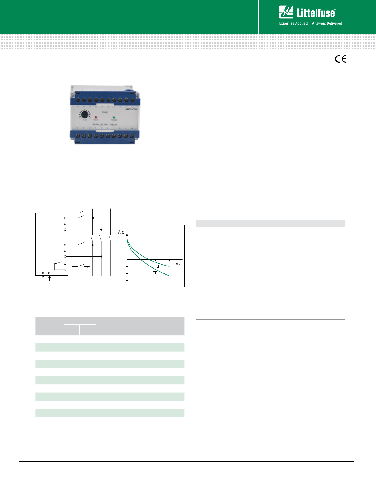
Simplified Circuit Diagram
L
1L2L3
1
2
T5000
(Paralleling Relay)
19920
Ordering Information
ORDERING
NUMBER
T5000.0010 450 V 400 V
T5000.0020 230 V
T5000.0030 480 V 415 V
T5000.0040 110 V 100 V
T5000.0050 127 V 120 V
T5000.0060 480 V 415 V Df=9-13.5°, D F=0.2-0.3 Hz
T5000.0070 450 V 400 V DU=15-20%, Df=9-13.5°, D F=0.2-0.3 Hz
T5000.0080 110 V 100 V DU=15-20%, Df=9-13.5°, D F=0.2-0.3n Hz
T5000.0090 450 V 400 V Df=9-13.5°, D F=0.2-0.3 Hz
T5000.0100 660 V
Other supply voltages, nominal currents and combi nations are availab le on request.
3
5
6
7
10
CLOSING
AUTOMATIC CLOSURE
SIGNAL
TERMINALS
1-1
5-7
1-3
6-7
FUNCTION
6
4
2
0
2
4
6
0.15 Hz
+ 50 msec.
Description
The T5000 Paralleling Relay is a check synchronizer, inhibiting
closure of circuit breaker if synchronizing parameters such as
voltage, frequency and phase angle are outside limits, thus
preventing generator damage and disturbance to the busbar.
The T5000 can also be used as synchronizing aid for manual
or automatic synchronization where voltage and frequency
are adjusted by the operator to roughly the values required,
and the unit will provide a closing signal to the circuit breaker
at phase accordance.
Automatic closure
In order to use the T5000 with automatic closure, terminals
19 and 20 should be interconnected, and the T5000 will now
operate as illustrated in graph at left.
Line I shows the closing signal directly from the T5000.
Line II shows the main contact closure with an additional
circuit breaker operation time of 50 msec.
Features & Benefits
FEATURES BENEFITS
Visual indication of
voltage and closing signal
Adjustable combined
setting, %U, of
synchronizing window
(delta frequency, delta voltage,
delta phase)
Automatic
closure function
Galvanic isolated inputs
DIN rail or screw-mount Easy installation
N-G continuity alarm
Passive filtering Eliminates nuisance tripping
Provides quick and concise status information
Facilita tes adjustment during ins tallation and
commissioning
Enables use with fast reacting circuit breakers
Protects the unit against high AC voltage and
currents from the installation including spikes
Monitors neutral-to-ground integrity and alarms
if ground path becomes open circuit
Specifications
Max. Voltage 660 V
Voltage Range 70 -110%
Consumption 2 x 5 VA max.
Frequency Range 45-65 Hz
Voltage Difference 10-15%
Frequency Difference 0.15 - 0.225 Hz Combined setting
Phase Difference 6-9°
Contact rating AC: 400 V, 5 A, 1250 VA; DC: 150 V, 5 A, 120 W
Operating Temperature –20°C to +70°C
Dielectric Test 2500 V, 50 Hz
EMC CE according to EN50081-1, EN50082-1,
EN50081-2, EN50082-2
Approvals Certified by major marine classification societies
Burn-in 50 hours before final test
Enclosure Material Polycarbonate, flame retardant
Weight 0.7 kg
Dimensions H 70 mm (2.7“); W 100 mm (3.9“);
D 115 mm (4.5“)
Installation 35 mm DIN rail or 4 mm (
}
3
/16”) screws
© 2013 Littelfuse Protection Relays & Controls
www.littelfuse.com/t5000
Rev: 4-A-050313
 Loading...