

Page 1
Protection Relays & Controls
Generator & Single-Function Protection–Overcurrent
T2400 SERIES
3-Phase Dual Overcurrent Relay
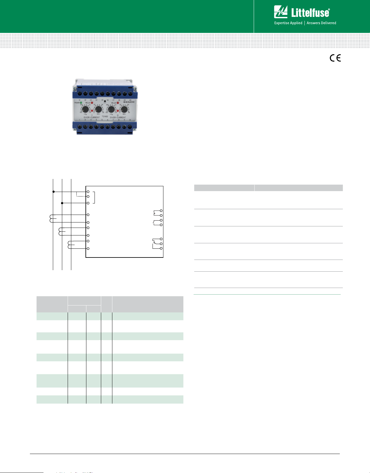
Simplified Circuit Diagram
1
2
U
3
11
I
1
12
13
I
2
14
15
I
3
16
L
1L2L3
Ordering Information
ORDERING
NUMBER
T2400.0010 230 V 5 A
T2400.0020 450 V 400 V 5 A
T2400.0030 110 V
T2400.0040 450 V 400 V 5 A
T2400.0050 480 V 415 V 5 A
T2400.0060 450 V 400 V 1 A
T2400.0070 450 V 400 V 5 A
T2400.0080 127 V 120 V 5 A
T2400.0090 24 Vdc 5 A
Latching o utput relays are reset by disconnectin g the power supply.
Other supply voltages and combinat ions are availabl e on request.
TERMINALS
1-3 2-3
100 V
T2400
SUPPLY
(3-Phase Dual
Overcurrent Relay)
II. OVERCURRENT
I
FUNCTION
N
5 A
Latching output on relay 1,
6-60 sec. delay on relay 1
Latching output on relay 1,
normally energized relay 1
I. OVERCURRENT
10
9
8
7
6
5
4
Description
The T2400 3-Phase Dual Overcurrent Relay includes two
combined overcurrent relays, designed for protection or
monitoring of generators and power transmissions. A typical
application is to use one of the overcurrent functions to trip the
generator circuit breaker, and the other overcurrent function to
trip a non-essential consumer.
The T2400 consists of two overcurrent circuits with similar
current settings and time delays. Each circuit detects the
highest of the 3 input currents and, if this exceeds the preset
level (0.5-1.4 x I
), the corresponding pick-up LED will indicate
N
and the delay timer will be started. After the preset time
(3-30 sec.) has expired, the corresponding output relay and
LED will be activated, provided that the current level was
exceeded for the entire delay time.
Features & Benefits
FEATURES BENEFITS
Accepts high supply
voltage variation
Ensures correct operation in spite of voltage
supply fluctuations (fulfills marine class
requirement)
Visual indication of
power, pick-up, and
Provides quick and concise status information
output trip
Direct line-line or line-
neutral voltage supply
(up to 690 Vac)
Combining 2 relays in
same enclosure
Galvanic isolated inputs
Simplifies design and installation.
No need for PTs.
Economic solution for non-essential load
tripping, and occupying less space in the
switch panel
Protects the unit against high AC voltage and
currents from the installation including spikes
DIN-rail or screw-mount
& adjustment by
Easy installation
potentiometers
Specifications
Trip Level 0.5-1.4 x I
Delay 3-30 sec.
Max. Voltage 660 V
Voltage Range 60-110 %
Consumption Voltage 5 VA at U
Current 0.3 VA at I
Continuous Current 2 x I
Frequency Range 45- 400 Hz
Output Relay Normally de-energized
Contact Rating AC: 400 V, 5 A, 2000 VA; DC: 150 V, 5 A, 150 W
Overall Accuracy ±5%
Repeatability ±1%
Operating Temperature –20°C to + 70°C
Dielectric Test 2500 V, 50 Hz
EMC CE according to EN50081-1, EN50082-1,
EN50081-2, EN50082-2
Approvals Certified by major marine classification societies
Burn-in 50 hours before final test
Enclosure Material Polycarbonate. Flame retardant
Weight 0.5 kg
Dimensions H 70 mm (2.76”); W 100 mm (3.94”);
D 115 mm (4.52”)
Installation 35 mm DIN rail or 4 mm (
N
N
N
N
3
/16”) screws
© 2013 Littelfuse Protection Relays & Controls
Littelfuse.com/t2400
Rev: 4-A-050213
 Loading...