

Page 1
Protection Relays & Controls
Generator & Single-Function Protection–3-Phase Short-Circuit
T2300 SERIES
3-Phase Short-Circuit Relay
Description
The T2300 3 Phase Short-Circuit Relay is designed for
protection of generators, power transmissions and
consumer’s supply against short circuit. The T2300 reacts on
a definite delay versus current level.
The T2300 detects the highest of the 3 input currents and,
if this exceeds the preset level (1.0 - 4.0 x I
LED will indicate and the delay timer will be started. After
the preset time (0.1-1.0 sec.) has expired, the normally
energized output relay will de-energize and the relay LED will
be activated, provided that the current level was exceeded
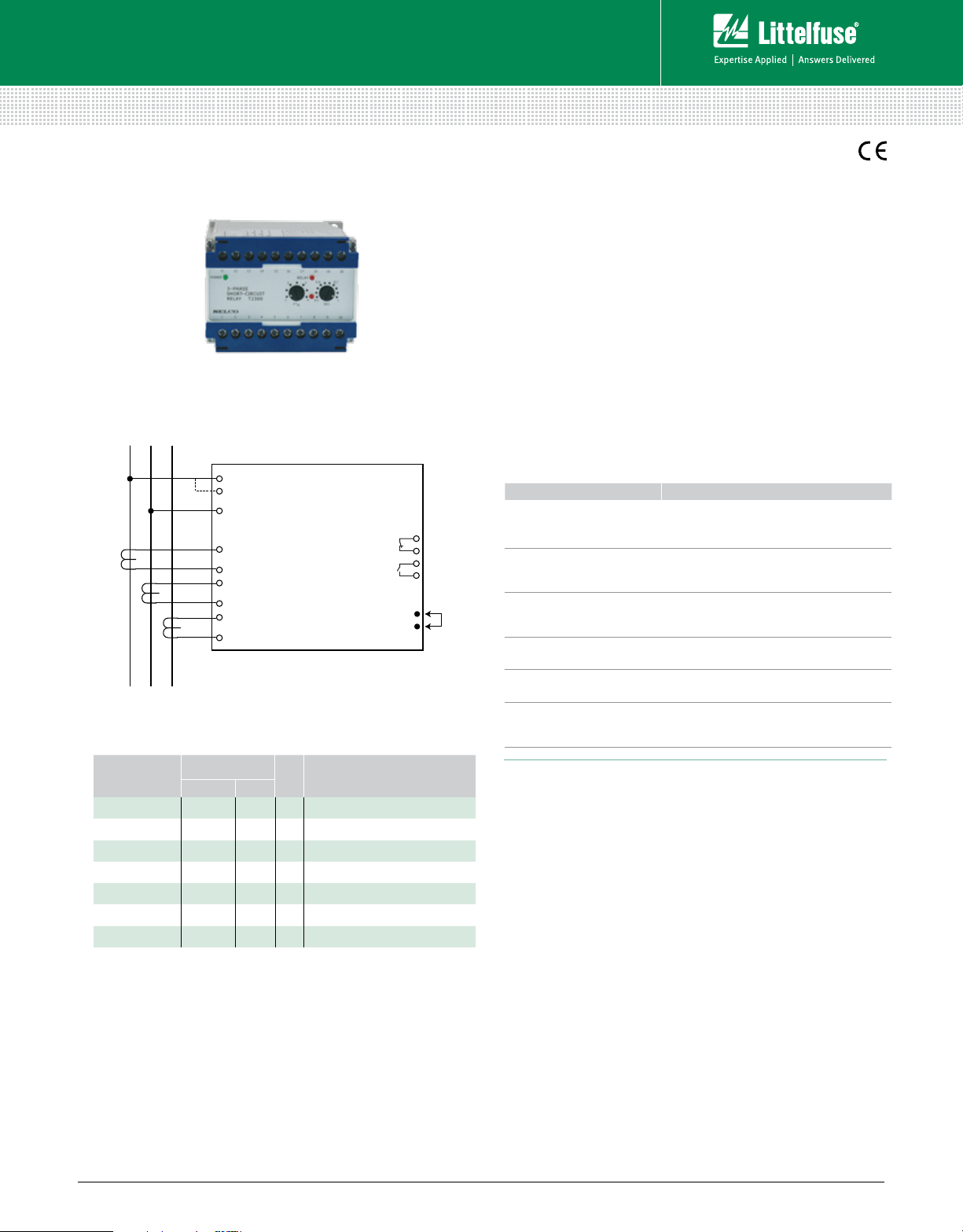
Simplified Circuit Diagram
1
2
SUPPLY
U
3
11
I
1
12
13
T2300
(3-Phase Short-Circuit Relay)
14
15
16
L
1L2L3
I
2
I
3
Ordering Information
SHORT CIRCUIT
10
9
8
7
6
5
for the entire delay time. The T2300 has a normally energized
output relay.
Features & Benefits
FEATURES BENEFITS
Accepts high supply
voltage variation
Visual indication of
power, pick-up, and
output trip
Direct line-line or lineneutral voltage supply
(up to 690 Vac)
Built-in capacitor
cack-up supply
Galvanic isolated inputs
DIN-rail or screw-mount
& adjustment by
potentiometers
), the pick-up
N
Ensures correct operation in spite of voltage
supply fluctuations (fulfills marine class
requirement)
Provides quick and concise status information
Simplifies design and installation.
No need for PTs.
Ensures correct operation in spite of drop in
the supply voltage
Protects the unit against high AC voltage and
currents from the installation including spikes
Easy installation
ORDERING
NUMBER
TERMINALS
1-3 2-3
I
N
FUNCTION
T2300.0100 230 V 5 A
T2300.0020 450 V 400 V 5 A
T2300.0030 24 Vdc 5 A
T2300.0040 24 Vdc 1 A
T2300.0050 450 V 400 V 5 A Normally de-energized output
T2300.0060 480 V 415 V 5 A
T2300.0070 230 V 1 A
Other supply voltages and combinat ions are availabl e on request.
© 2013 Littelfuse Protection Relays & Controls
Littelfuse.com/t2300
Specifications
Trip Level 1.0-4.0 x I
Delay 0.1-1.0 sec.
Max. Voltage 660 V
Voltage Range 60-110 %
Consumption Voltage 5 VA at U
Current 0.3 VA at I
Continuous Current 2 x I
Frequency Range 45- 400 Hz
Output Relay Normally de-energized, latching, resetable
Contact Rating AC: 400 V, 5 A, 2000 VA
DC: 150 V, 5 A, 150 W
Overall Accuracy ±5%
Repeatability ±1%
Operating Temperature –20°C to + 70°C
Dielectric Test 2500 V, 50 Hz
EMC CE according to EN50081-1, EN50082-1,
EN50081-2, EN50082-2
Approvals Certified by major marine classification societies
Burn-in 50 hours before final test
Enclosure Material Polycarbonate. Flame retardant
Weight 0.5 kg
Dimensions H 70 mm (2.76”); W 100 mm (3.94”);
D 115 mm (4.52”)
Installation 35 mm DIN rail or 4 mm (
N
N
N
N
3
/16”) screws
Rev 4-A-050213
 Loading...