

Page 1
Protection Relays & Controls
9
5
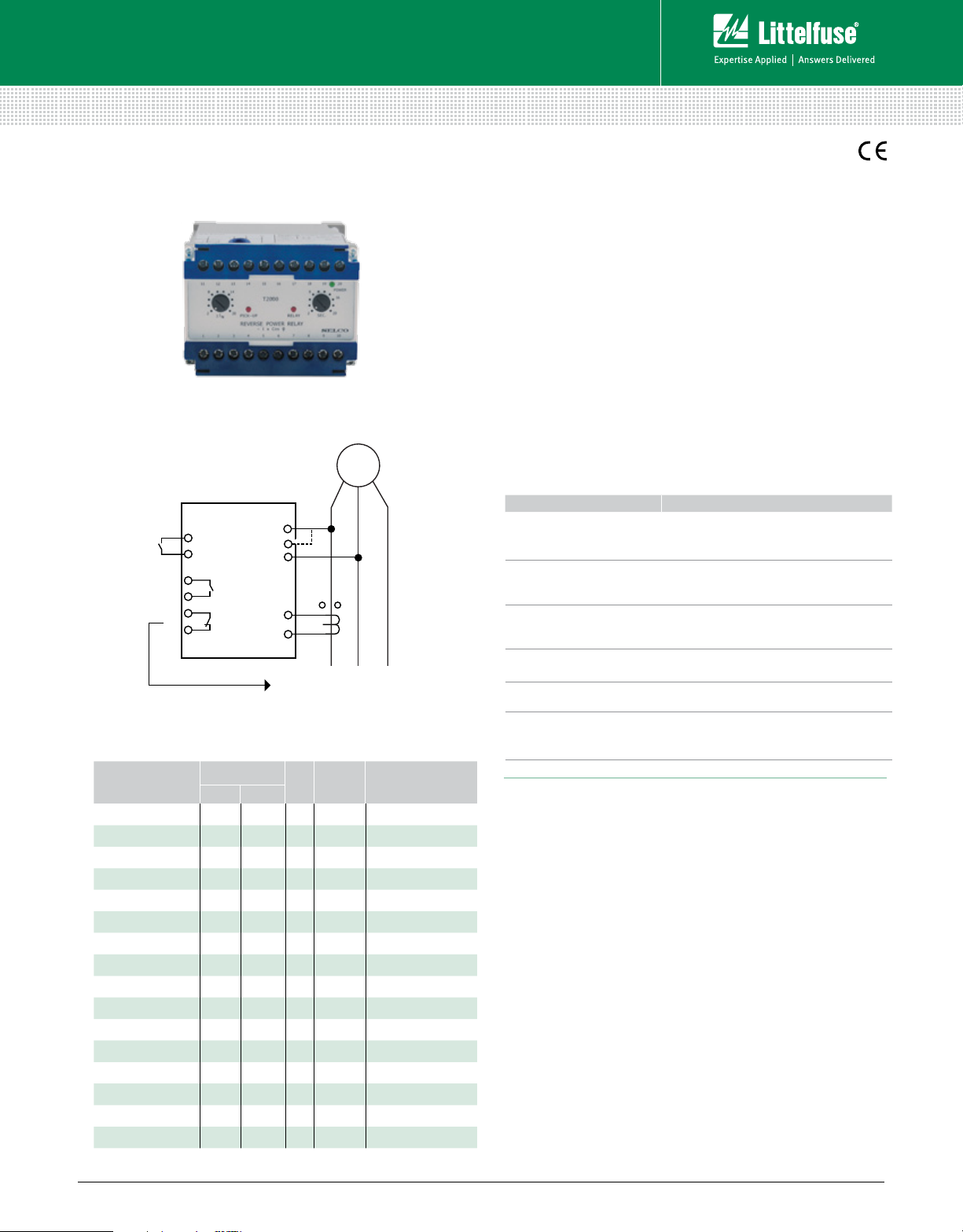
C/B TRIP
10
6
L - L SUPPLY
7
8
1
3
2
RESET
13
14
LOAD
1
2
3
LL L
T2000
(Reverse
Power
Relay)
G
Generator & Single-Function Protection–Reverse Power
T2000 SERIES
Reverse Power Relay
Simplified Circuit Diagram
Ordering Information
ORDERING
NUMBER
T2000.0010 230 V 5 A L-N
T2000.0020 450 V 400 V 5 A L-L
T2000.0030 127 V 120 V 5 A L-N
T2000.0040 110 V 100 V 5 A L-L
T2000.0050 110 V 100 V 5 A L-L No time delay
T2000.0060 230 V 1 A L-N
T2000.0070 660 V 5 A L-L
T2000.0080 450 V 400 V 5 A L-N Delay 0.2 - 2.0 sec.
T2000.0090 127 V 120 V 5 A L-L
T2000.0100 110 V 100 V 1 A L-L
T2000.0110 450 V 400 V 5 A L-L No time delay
T2000.0120 480 V 415 V 5 A L-L
T2000.0130 230 V 5 A L-N No time delay
T2000.0140 230 V 5 A L-L
T2000.0150 480 V 415 V 1 A L-L
T2000.0160 450 V 400 V 1 A L-L
Other supply voltages and combinations are available on request .
TERMINALS
1-3 2-3
I
SUPPLY FUNCTION
N
Description
Under parallel operation, the T2000 Reverse Power Relay will
protect the generator from being run as an electric motor. The
T2000 will protect the prime mover of the generator against
physical damage, but will also protect the parallel running
generators from overload caused by the inversed load shift in
a reverse power situation.
The T2000 calculates I x cos F, representing the active
power. If the active power becomes negative and exceeds
the preset level (2-20%), the pick-up LED will indicate
this and the delay timer will be started. After the preset
time (2-20 sec.) has expired, the output relay and LED will
be activated, provided that the reverse power level was
exceeded for the entire delay time.
Features & Benefits
FEATURES BENEFITS
Accepts high supply
voltage variation
Visual indication of
power, pick-up, and
output trip
Direct line-line or lineneutral voltage supply
(up to 690 Vac)
Available with instant
output trip
Galvanic isolated inputs
DIN-rail or screw-mount
& adjustment by
potentiometers
Ensures correct operation in spite of voltage
supply fluctuations (fulfills marine class
requirement)
Provides quick and concise status information
Simplifies design and installation. No need for
PTs or separate power supply
Enables alternative use for detection of current
direction
Protects the unit against high AC voltage and
currents from the installation including spikes
Easy installation
Specifications
Trip Level 2-20% I
Delay 2-20 sec.
Max. Voltage 660 V
Voltage Range 50-110%
Consumption 5 VA at U
Continuous Current 2 x I
Frequency Range 45- 400 Hz
Output Relay Normally de-energized, latching, resetable
Contact Rating AC: 400 V, 5 A, 1250 VA
DC: 150 V, 5 A, 120 W
Overall Accuracy ±5%
Repeatability ±1%
Operating Temperature –20°C to + 70°C
EMC CE according to EN50081-1, EN50082-1,
EN50081-2, EN50082-2
Approvals Certified by major marine classification societies
Burn-in 50 hours before final test
Enclosure Material Polycarbonate. Flame retardant
Weight 0.5 kg
Dimensions H 70 mm (2.76”); W 100 mm (3.94”);
D 115 mm (4.52”)
Installation 35 mm DIN rail or 4 mm (
N
N
N
3
/16”) screws
© 2013 Littelfuse Protection Relays & Controls
Littelfuse.com/t2000
Rev: 4-A-050213
 Loading...