

Littelfuse Sxx70x User Manual
Sxx65x & Sxx70x Series
Teccor® brand Thyristors
65 / 70 Amp Standard SCRs
Description
Excellent unidirectional switches for phase control
applications such as heating and motor speed controls.
Standard phase control SCRs are triggered with few
milliamperes of current at less than 1.5V potential.
Features & Benefits
Agency Approval
Agency Agency File Number
®
J & K Packages: E71639
Main Features
Symbol Value Unit
I
T(RMS)
V
DRM/VRRM
I
GT
65 & 70 A
400 to 1000 V
50 mA
Absolute Maximum Ratings
t3P)4DPNQMJBOU
t(MBTToQBTTJWBUFE
junctions
t7PMUBHFDBQBCJMJUZVQ
to 1000 V
t4VSHFDBQBCJMJUZVQUP
950 A
Applications
Typical applications are AC solid-state switches, industrial
power tools, exercise equipment, white goods and
commercial appliances.
Internally constructed isolated packages are offered for
ease of heat sinking with highest isolation voltage.
Schematic Symbol
AK
G
Symbol Parameter Test Conditions Value Unit
I
T(RMS)
I
T(AV)
I
TSM
2
tI
I
RMS on-state current
Average on-state current
Peak non-repetitive surge current
2
t Value for fusing tp = 8.3 ms 3745 A2s
di/dt Critical rate of rise of on-state current
I
GM
P
G(AV)
T
stg
T
J
Sxx65x & Sxx70x Series
Operating junction temperature range -40 to 125 °C
Peak gate current
Average gate power dissipation
Storage temperature range -40 to 150 °C
Sxx65J
Sxx65K
Sxx70W T
Sxx65J
Sxx65K
Sxx70W T
single half cycle; f = 50Hz;
T
(initial) = 25°C
J
single half cycle; f = 60Hz;
(initial) = 25°C
T
J
f = 60Hz ; T
T
J
PW = µS
T
J
331
T
= 75°C 65
C
= 80°C 70
C
TC = 75°C 41.0 A
= 80°C 45.0 A
C
800
950
= 125°C
J
= 125°C
= 125°C
200 A/s
5.0 A
1. 0 W
Specifications are subject to change without notice.
A
A
©2013 Littelfuse, Inc
Revised: 09/23/13
Teccor® brand Thyristors
65 / 70 Amp Standard SCRs
Electrical Characteristics (T
= 25°C, unless otherwise specified)
J
Symbol Test Conditions Value Unit
I
GT
V
GT
dv/dt
VD = 12V; RL = 30
400V
V
= V
; gate open; TJ = 100°C
D
DRM
600V 600
800V 500
1000V 250
MAX. 50
MIN. 5
MAX. 2.0 V
650
MIN.
400V 550
VD = V
; gate open; TJ = 125°C
DRM
600V 500
800V 475
V
GD
I
H
t
q
t
gt
Note :
(1) I
=2A; tp=50µs; dv/dt=5V/µs; di/dt=-30A/µs
T
VD = V
IG = 2 x IGT; PW = 15µs; IT = 140A TYP. 2.5 s
; RL = 3.3 k; TJ = 125°C MIN. 0.2 V
DRM
IT = 400mA (initial) MAX. 80 mA
(1) MAX. 35 s
Static Characteristics
mA
V/s
Symbol Test Conditions Value Unit
V
TM
65A Device IT = 130A; tp = 380s
70A Device I
= 140A; tp = 380s
T
TJ = 25°C
MAX. 1.8 V
o7
1000 V 30
20
o7 1500
I
DRM
/ I
RRM
V
/ V
DRM
RRM
= 100°C
J
800V 2000
MAX.
T
1000V 5000
7o7 3000
= 125°C
T
J
800V 5000
Thermal Resistances
Symbol Parameter Value Unit
R
(J-C)
Note: xx = voltage
Junction to case (AC)
Sxx65J
Sxx65K
Sxx70W 0.6
0.86
A
°C/W
Sxx65x & Sxx70x Series
332
Specifications are subject to change without notice.
©2013 Littelfuse, Inc
Revised: 09/23/13
Teccor® brand Thyristors
65 / 70 Amp Standard SCRs
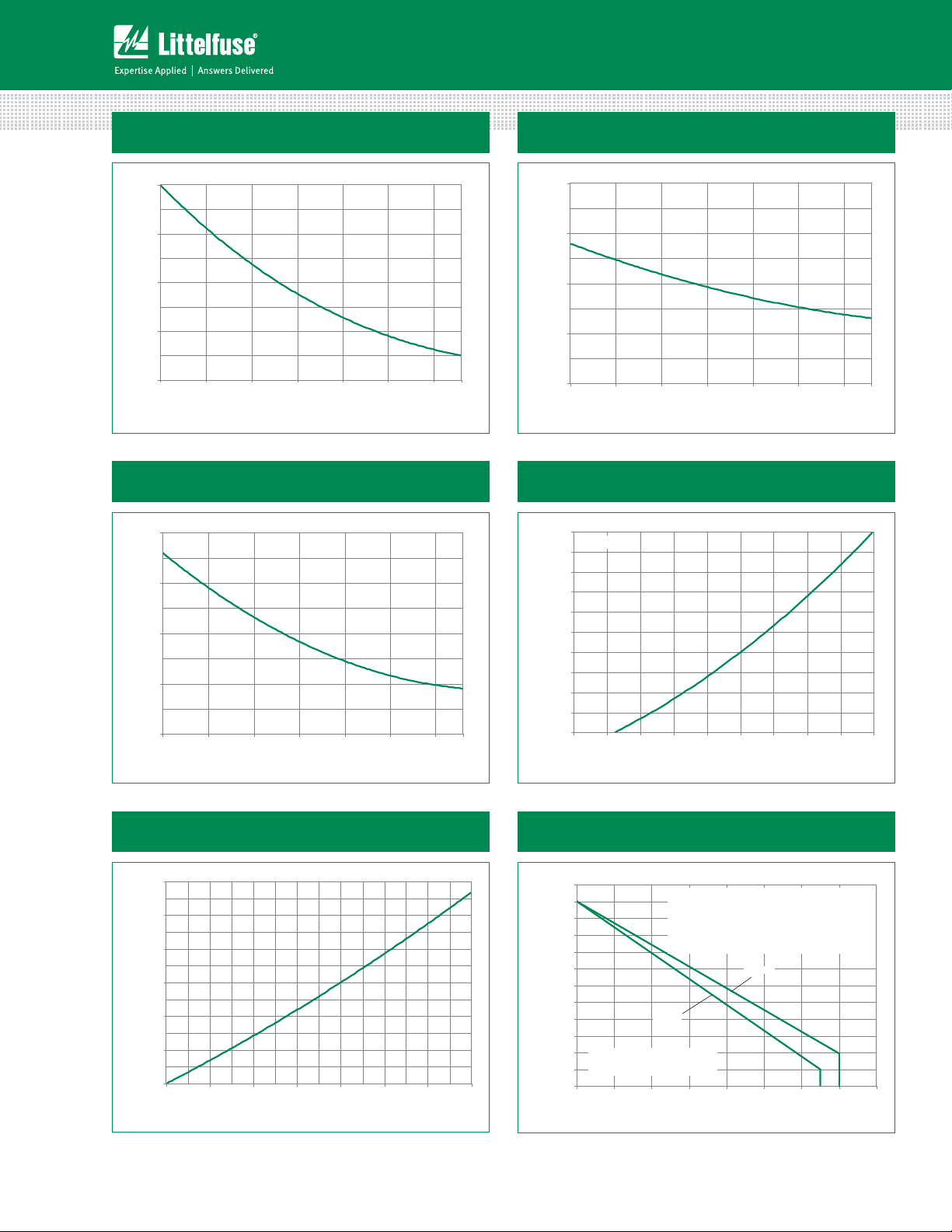
Figure 1: Normalized DC Gate Trigger Current
vs. Junction Temperature
2.0
1.5
= 25°C)
J
(T
GT
1.0
/I
GT
0.5
Ratio of I
0.0
-40 -15 10 35 60 85 11 0
Junction Temperature (TJ) -- (°C)
Figure 3: Normalized DC Holding Current
vs. Junction Temperature
2.0
1.5
=25°C)
J
(T
H
1.0
/I
H
Ratio of I
0.5
0.0
-40 -15 10 3 5 60 85 11 0
Junction Temperature (TJ) -- (°C)
125
125
Figure 2: Normalized DC Gate Trigger Voltage
vs. Junction Temperature
2.0
1.5
=25°C)
J
(T
GT
1.0
/V
GT
0.5
Ratio of V
0.0
-40 -15 10 35 60 85 11 0
Junction Temperature (TJ) -- (°C)
Figure 4: On-State Current vs. On-State
Voltage (Typical)
200
TJ = 25°C
180
160
) – Amps
T
140
120
100
80
60
40
20
Instantaneous On-state Current (i
0
0.7 0.8 0.9 1.0 1.1 1.2 1.3 1.4 1.5 1.6
Instantaneous On-state Voltage (vT) – Volts
125
Figure 5: Power Dissipation (Typical)
vs. RMS On-State Current
60
50
40
30
] - (W atts)
D (AV)
[P
20
10
Average On-State Power Dissipation
0
010203040506
RMS On-State Current [I
Note: xx = voltage
Sxx65x & Sxx70x Series
T(R MS)
] - (Am ps)
070
333
Figure 6: Maximum Allowable Case Temperature
vs. RMS On-State Current
130
125
120
115
110
105
)-°C
100
C
(T
95
90
85
CURRENT WAVEFORM: Sinusoidal
80
Maximum Allowable Case Temperature
LOAD: Resistive or Inductive
75
CONDUCTION ANGLE: 180°
70
01020304050607
The "K" package rating with its narrow leads is intended
for high surge condition use only and not recommended for >50A rms continuous current use since lead
temperature depending on lead length can exceed PCB
solder melting temperature. "J" or "W" packages are
recommended for >50A rms continuous current requirements.
Sxx70W
Sxx65K
Sxx65J
RMS On-State Current [I
T(RMS)
] - Amps
Specifications are subject to change without notice.
©2013 Littelfuse, Inc
Revised: 09/23/13
080
 Loading...