

Littelfuse Sxx40x User Manual
Sxx40x Series
Teccor® brand Thyristors
40 Amp Standard SCRs
Description
Excellent unidirectional switches for phase control
applications such as heating and motor speed controls.
Standard phase control SCRs are triggered with few
milliamperes of current at less than 1.5V potential.
Features & Benefits
Main Features
Symbol Value Unit
I
T(RMS)
V
DRM/VRRM
I
GT
40 A
400 to 1000 V
40 mA
Absolute Maximum Ratings
t3P)4DPNQMJBOU
t(MBTToQBTTJWBUFE
junctions
t7PMUBHFDBQBCJMJUZVQ
to 1000 V
t4VSHFDBQBCJMJUZVQUP
520 A
Applications
Typical applications are AC solid-state switches, industrial
power tools, exercise equipment, white goods and
commercial appliances.
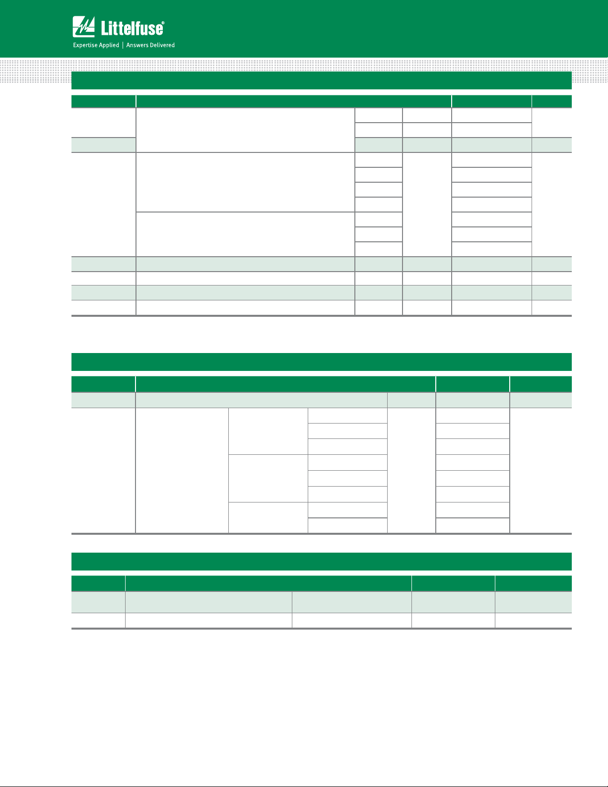
Schematic Symbol
AK
G
Symbol Parameter Test Conditions Value Unit
I
T(RMS)
I
T(AV)
I
TSM
2
tI
I
di/dt Critical rate of rise of on-state current
I
GM
P
G(AV)
T
stg
T
J
Sxx40x Series
RMS on-state current TC = 100°C 40 A
Average on-state current TC = 100°C 25.0 A
Peak non-repetitive surge current
2
t Value for fusing tp = 8.3 ms 1122 A2s
Peak gate current
Average gate power dissipation
single half cycle; f = 50Hz;
T
(initial) = 25°C
J
single half cycle; f = 60Hz;
T
(initial) = 25°C
J
f = 60Hz ; T
T
= 125°C
J
T
= 125°C
J
= 125°C
J
430
520
175 A/s
3.5 A
0.8 W
Storage temperature range -40 to 150 °C
Operating junction temperature range -40 to 125 °C
313
Specifications are subject to change without notice.
A
©2013 Littelfuse, Inc
Revised: 09/23/13
Teccor® brand Thyristors
40 Amp Standard SCRs
Electrical Characteristics (T
= 25°C, unless otherwise specified)
J
Symbol Test Conditions Value Unit
I
GT
V
GT
VD = 12V; RL = 30
V
= V
D
dv/dt
VD = V
V
GD
I
H
t
q
t
gt
Note :
(1) I
=2A; tp=50µs; dv/dt=5V/µs; di/dt=-30A/µs
T
VD = V
IT = 400mA (initial) MAX. 60 mA
(1) MAX. 35 s
IG = 2 x IGT; PW = 15µs; IT = 80A TYP. 2.5 s
400V
; gate open; TJ = 100°C
DRM
600V
800V
1000V
400V
; gate open; TJ = 125°C
DRM
600V
800V
; RL = 3.3 k; TJ = 125°C MIN. 0.2 V
DRM
MAX. 40
MIN. 5
MAX. 1.5 V
650
600
500
MIN.
250
550
500
475
Static Characteristics
mA
V/s
Symbol Test Conditions Value Unit
V
TM
IT = 80A; tp = 380s MAX. 1.8 V
TJ = 25°C
o7
800 V 20
10
1000 V 30
o7 1000
I
DRM
/ I
RRM
V
/ V
DRM
RRM
T
= 100°C
J
800V 1500
MAX.
1000V 5000
o7 2000
= 125°C
T
J
800V 3000
Thermal Resistances
Symbol Parameter Value Unit
R
(J-C)
R
(J-A)
Note: xx = voltage
Junction to case (AC)
Junction to ambient Sxx40R 40 °C/W
Sxx40R /
Sxx40N
0.6 °C/W
A
Sxx40x Series
314
Specifications are subject to change without notice.
©2013 Littelfuse, Inc
Revised: 09/23/13
Teccor® brand Thyristors
40 Amp Standard SCRs
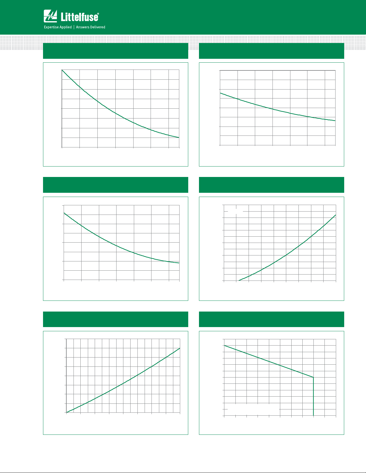
Figure 1: Normalized DC Gate Trigger Current
vs. Junction Temperature
2.0
1.5
= 25°C)
J
(T
GT
1.0
/ I
GT
0.5
Ratio of I
0.0
-40 -15 10 35 60 85 11 0
Junction Temperature (TJ)-- (°C)
Figure 3: Normalized DC Holding Current
vs. Junction Temperature
2.0
1.5
= 25°C)
J
(T
H
1.0
/ I
H
0.5
Ratio of I
125
Figure 2: Normalized DC Gate Trigger Voltage
vs. Junction Temperature
2.0
1.5
= 25°C)
J
(T
GT
1.0
/ V
GT
0.5
Ratio of V
0.0
-40 -15 10 35 60 85 110
Junction Temperature (TJ ) --(°C)
Figure 4: On-State Current vs. On-State
Voltage (Typical)
120
TJ = 25°C
100
80
) – Amps
T
60
40
Current (i
Instantaneous On-state
20
125
0.0
-40 -15 10 35 60 85
Junction Temperature (T J) -- (°C)
Figure 5: Power Dissipation (Typical)
vs. RMS On-State Current
40
35
30
25
20
] - (Watts)
D(AV)
15
[P
10
5
Average On-State Power Dissipation
0
0 5 10 15 20 25 30 35 40
Sxx40x Series
RMS On-State Current [I
T(RMS)
] - (Amps)
110
125
0
0.7 0.8 0.9 1.0 1.1 1.2 1.3 1.4 1.5 1.6
Instantaneous On-state Voltage (vT) – Volts
Figure 6: Maximum Allowable Case Temperature
vs. RMS On-State Current
130
125
120
115
)- °C
C
110
105
100
95
90
Maximum Allowable
85
Case Temperature (T
80
CURRENT WAVEFORM: Sinusoidal
LOAD: Resistive or Inductive
75
CONDUCTION ANGLE: 180°
70
0 5 10 15 20 25 30 35 40 4550
315
RMS On-State Current [I
Specifications are subject to change without notice.
T(RMS)
] - Amps
©2013 Littelfuse, Inc
Revised: 09/23/13
 Loading...