

Littelfuse Sxx16x User Manual
Sxx15x & Sxx16x Series
K
Teccor® brand Thyristors
15 and 16 Amp Standard SCRs
Description
Excellent unidirectional switches for phase control
applications such as heating and motor speed controls.
Standard phase control SCRs are triggered with few
milliamperes of current at less than 1.5V potential.
Features & Benefits
Agency Approval
Agency Agency File Number
®
L Package: E71639
Main Features
Symbol Value Unit
I
T(RMS)
V
DRM/VRRM
I
GT
15 & 16 A
400 to 1000 V
30 mA
Absolute Maximum Ratings — Standard SCRs
t3P)4DPNQMJBOU
t(MBTToQBTTJWBUFE
junctions
t7PMUBHFDBQBCJMJUZVQ
to 1000 V
t4VSHFDBQBCJMJUZVQUP
225 A
Applications
Typical applications are capacitive discharge systems for
strobe lights, nailers, staplers and gas engine ignition. Also
controls for power tools, home/brown goods and white
goods appliances.
Internally constructed isolated packages are offered for
ease of heat sinking with highest isolation voltage.
Schematic Symbol
A
G
Symbol Parameter Test Conditions Value Unit
I
T(RMS)
I
T(AV)
I
TSM
2
tI
I
RMS on-state current
Average on-state current
Peak non-repetitive surge current
2
t Value for fusing tp = 8.3 ms 210 A2s
di/dt Critical rate of rise of on-state current
I
GM
P
G(AV)
T
stg
T
J
Note: xx = voltage
Sxx15x & Sxx16x Series
Operating junction temperature range -40 to 125 °C
Peak gate current
Average gate power dissipation
Storage temperature range -40 to 150 °C
Sxx15L T
Sxx16R
Sxx16N
Sxx15L T
Sxx16R
Sxx16N
single half cycle; f = 50Hz;
T
(initial) = 25°C
J
single half cycle; f = 60Hz;
(initial) = 25°C
T
J
f = 60 Hz ; T
T
= 125°C
J
T
= 125°C
J
287
= 90°C 15
C
T
= 110°C 16
C
= 90°C 9.5
C
= 110°C 10.0
T
C
= 125°C
J
188
225
125 A/s
3A
0.6 W
Specifications are subject to change without notice.
A
A
A
©2013 Littelfuse, Inc
Revised: 09/23/13
Teccor® brand Thyristors
15 and 16 Amp Standard SCRs
Electrical Characteristics (T
= 25°C, unless otherwise specified)
J
Symbol Test Conditions
I
GT
V
GT
VD = 12V; RL = 60
V
= V
; gate open; TJ = 100°C
D
DRM
dv/dt
VD = V
V
GD
I
H
t
q
t
gt
Note: xx = voltage, x = package
(1) I
=2A; tp=50µs; dv/dt=5V/µs; di/dt=-30A/µs
T
VD = V
IT = 200mA (initial) MAX. 40 mA
IT=2A; tp=50µs; dv/dt=5V/µs; di/dt=-30A/µs MAX. 35 s
IG = 2 x IGT PW = 15µs IT = 12A TYP. 2 s
; gate open; TJ = 125°C
DRM
RL = 3.3 k TJ = 110°C MIN. 0.2 V
DRM
400V
600V
800V
1000V
400V
600V
800V
Value
Sxx15x
Unit
Sxx16x
MAX. 30
MIN. 1
mA
MAX. 1.5 V
450
425
400
MIN.
200
V/s
350
325
300
Static Characteristics
Symbol Test Conditions Value Unit
15A Device IT = 30A; tp = 380 µs
V
TM
16A Device I
= 32A; tp = 380 µs
T
400 - 600V
TJ = 25°C
800 - 1000V 20
MAX. 1.6 V
10
400 - 600V 500
I
DRM
/ I
RRM
V
= V
DRM
RRM
T
= 100°C
J
800V 1000
MAX.
1000V 3000
400 - 600V 1000
= 125°C
T
J
800V 2000
Thermal Resistances
Symbol Parameter Value Unit
R
(J-C)
R
(J-A)
Note: xx = voltage
Junction to case (AC)
Junction to ambient
Sxx16R/ Sxx16N 1.1
Sxx15L 2.5
Sxx16R 40
Sxx15L 50
A
°C/W
°C/W
Sxx15x & Sxx16x Series
288
Specifications are subject to change without notice.
©2013 Littelfuse, Inc
Revised: 09/23/13
Teccor® brand Thyristors
15 and 16 Amp Standard SCRs
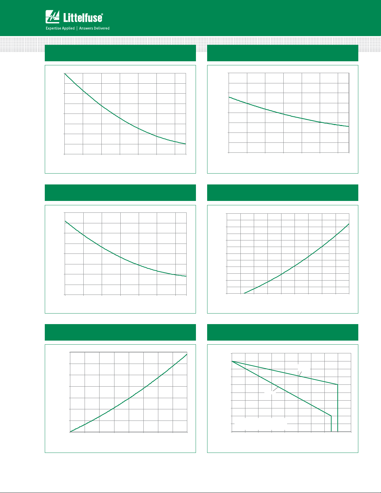
Figure 1: Normalized DC Gate Trigger Current
vs. Junction Temperature
2.0
1.5
= 25°C)
J
(T
GT
1.0
/ I
GT
0.5
Ratio of I
0.0
-40 -15 10 35 60 85 11 0
Junction Temperature (TJ) -- (ºC)
Figure 3: Normalized DC Holding Current
vs. Junction Temperature
2.0
1.5
= 25°C)
J
(T
H
1.0
/ I
H
Ratio of I
0.5
0.0
-40 -15 10 35 60 85 110
Junction Temperature (TJ) -- (°C)
125
125
Figure 2: Normalized DC Gate Trigger Voltage
vs. Junction Temperature
2.0
1.5
= 25ºC)
J
(T
GT
1.0
/ V
GT
0.5
Ratio of V
0.0
-40 -15 10 35 60 85 11 0
Junction Temperature (TJ) -- (°C)
Figure 4: On-State Current vs. On-State
Voltage (Typical)
60
50
) – Amps
T
40
30
20
10
Instantaneo us On-state Curren t (i
0
0.7 0.8 0.9 1.0 1.1 1.2 1.3 1.4 1.5 1.6
Instan tane ous On-state Volta ge (vT) – Vol ts
125
Figure 5: Power Dissipation (Typical)
vs. RMS On-State Current
14
12
10
8
] - (Watts)
6
D(AV)
[P
4
2
Average On-State Power Dissipation
0
0246810121416
RMS On -Sta te Cu rre nt [I
Sxx15x & Sxx16x Series
T(RMS )
] - (Am ps)
Figure 6: Maximum Allowable Case Temperature
vs. RMS On-State Current
130
289
125
120
115
) - °C
C
110
105
100
95
Temperature (T
Maximum Allowable Case
90
CURRENT WAVEFORM: Sinusoidal
LOAD: Resistive or Inductive
85
CONDUCTION ANGLE: 180°
80
024681012141
Sxx15L
RMS On-State Current [I
Sxx16R
Sxx16N
T(RMS)
Specifications are subject to change without notice.
] - Amps
618
©2013 Littelfuse, Inc
Revised: 09/23/13
 Loading...