

Surge Protection Devices
SPD2 PV SERIES
Type 2/Type 1CA Pluggable Multi-Pole for PV Systems
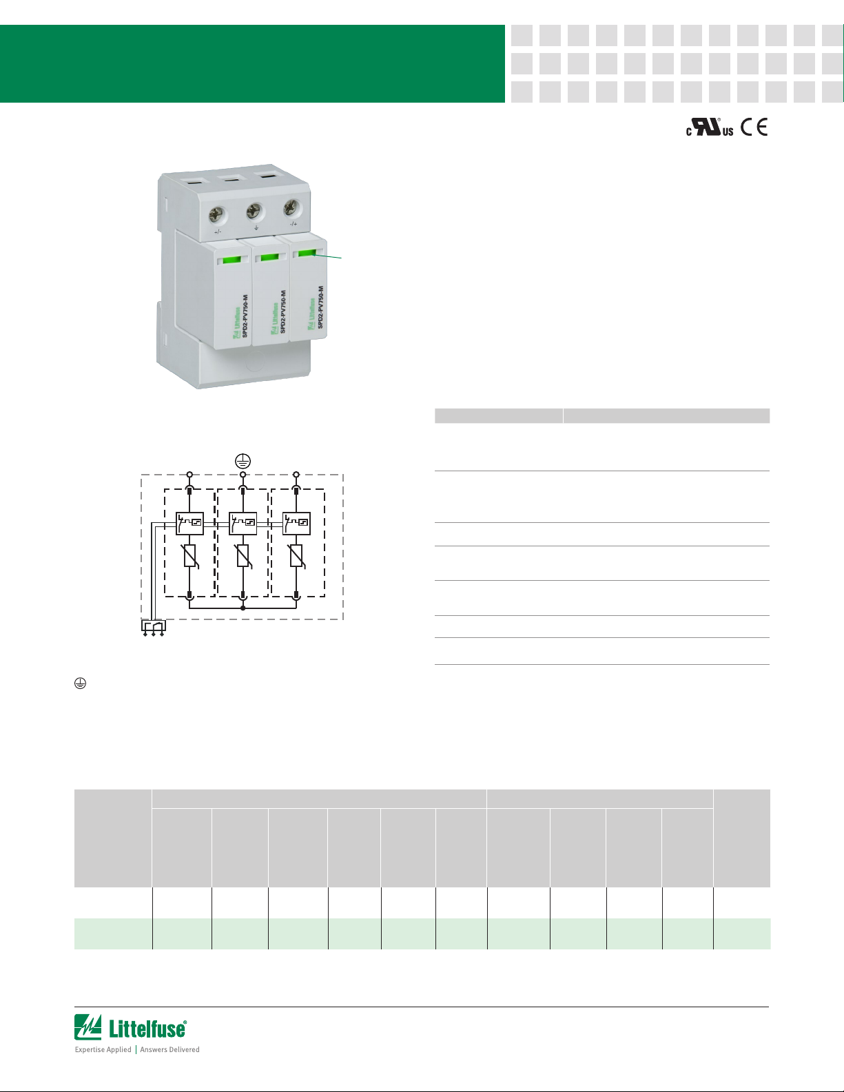
Description
Visual Life
Indicator
Internal Configuration
+/- -/+
TD TD TD
Surge protection devices (SPDs) provide equipment protection
from transient overvoltage events lasting micro-seconds. By
limiting the overvoltage to the equipment during these events,
costly damage and downtime can be mitigated.
The surge protection devices for solar string box and inverter
applications are available in 1100 and 1500 VDC in the 3+0
configuration.
Features & Benefits
FEATURES BENEFITS
Capability to clamp and
withstand high-energy
transients
No additional
overcurrent protection
devices required in
UL applications
Compact footprint
Visual life indicator
Ensures low-residual voltage during high-energy
surge events and higher nominal discharge current
to prevent disruption, downtime, and degradation or
damage to equipment
Reduces the number of components and costs
required for protection
I
ncreases panel design flexibility
Quick visual determines module replacement status
to avoid loss of protection
Fast and simple to replace, minimizing maintenance
and downtime. No tools required
RC
14 11 12
Pluggable modules
Thermal protection Eliminates catastrophic failure
IP20 protection rating Finger-safe design increases worker protection
Legend
Protective Earth
RC Optional Remote Contact
TD Thermal Disconnection
Module & Base Ordering Information
IEC Electrical UL Electrical
Ordering
Number
SPD2-PV11-3P0-R 1100 V 20 kA 40 kA 50 kA 4200 V 9 kA 1100 V 3000 V 20 kA 50 kA
SPD2-PV15-3P0-R 1500 V 15 kA 40 kA 40 kA 4800 V 9 kA 1500 V 4000 V 20 kA 65 kA
Maximum
Continuous
Operating
DC Voltage
(U
CPV
)
Nominal
Discharge
Current
(8/20 µs)
(In)
Maximum
Discharge
Current
(8/20 µs)
(I
)
max
Total
Discharge
Current
(I
)
Total
Voltage
Protection
Level (Up)
ShortCircuit
Current
Rating
(I
SCPV
)
Maximum
Permitted
DC Voltage
(I
)
pvdc
Voltage
Protection
Rating
(VPR)
Nominal
Discharge
Current
(8/20 µs)
(In)
ShortCircuit
Current
Rating
(SCCR)
Single Unit
Weight
333 g
(0.734 lb)
363 g
(0.800 lb)
1 of 2
Surge Protection Devices
SPD2 PV SERIES
Module & Base Part Numbering System Module Only Part Numbering System
SPD2 PV VV XPZ R
Series
Photovoltaic
Maximum Continuous
Operating DC Voltage
Optional Remote
Contact
Neutral
(1=yes or 0=no)
Number of Poles
Series
Photovoltaic
SPD2 PV VVV M
Module Only
DC Voltage
in Hundreds
Replacement Module Ordering Information
IEC Electrical UL Electrical
Ordering
Number
SPD2-PV550-M 1100 V 20 kA 40 kA 50 kA 4200 V 9 kA 1100 V 3000 V 20 kA 50 kA 61 g (0.134 lb)
SPD2-PV750-M 1500 V 15 kA 40 kA 40 kA 4800 V 9 kA 1500 V 4000 V 20 kA 65 kA 71 g (0.157 lb)
Maximum
Continuous
Operating
DC Voltage
(U
CPV
)
Nominal
Discharge
Current
(8/20 µs)
(In)
Maximum
Discharge
Current
(8/20 µs)
(I
)
max
Total
Discharge
Current
(I
)
Total
Voltage
Protection
Level (Up)
ShortCircuit
Current
Rating
(I
SCPV
)
Maximum
Permitted
DC Voltage
(I
)
pvdc
Voltage
Protection
Rating
(VPR)
Nominal
Discharge
Current
(8/20 µs)
(In)
ShortCircuit
Current
Rating
(SCCR)
Single Unit
Weight
Specifications
Mode of Protection ( + ) - PE, ( - ) - PE, ( + ) - ( - )
Nominal Discharge Current
(8/20 µs) (In) 20 kA
Maximum Discharge Current
(8/20 µs) (I
) Up to 40 k A
max
Protective Elements High Energy MOV
Response Time (t
Number of Por ts
) < 25 ns
A
1
Mechanical & Environmental
Operating Temperature
Range (Ta) -40 °C to +80 °C (-40 °F to +185 °F)
Permissible Operating
Humidity (RH) 5% to 95%
Altitude (max) 4,000 m (13,123 ft)
Terminal Screw Torque) (M
) 4.5 Nm (39.9 lbf-in)
max
Conductor Cross Section (max) 35 mm² (2 AWG) (Solid, Stranded)/
25 mm2 (4 AWG) (Flexible)
Mounting 35 mm DIN Rail, EN60715
Degree of Protection IP20 (built-in)
Housing Material Thermoplastic: Extinguishing Degree
UL 94 V-0
Thermal Protection Yes
Operating State/Fault
Indication Green Flag/No Green Flag
Remote Contact Switching
Capacity AC: 250 V/1 A, 125 V/1 A;
DC: 48 V/0.5 A, 24 V/0.5 A, 12 V/0.5 A
Remote Contact Conductor
Cross Section (max) 1.5 mm2 (16 AWG) (Solid)
Standards Passed EN 50539-11:2013+A1:2014
UL 1449 4th Edition; E320116
Product Dimensions
3TE Module and Base H 90.7 mm (3.57”); W 53.8 mm (2.11”);
D 66.1 mm (2.60”)
1TE Replacement Module H 45.0 mm (1.77”); W 18.0 mm (0.71”);
D 57.2mm (2.25”)
Package Dimensions
3TE Module and Base H 102.0 mm (4.01”); W 64.0 mm (2.52”);
D 110.0 mm (4.33”)
1TE Replacement Module
H 102.0 mm (4.01”); W 28.0 mm (1.10”);
D 110.0 mm (4.33”)
Warranty – Visit www.littelfuse.com/warranty for details.
Disclaimer Notice – Information furnished is believed to be accurate and reliable. However, users should independently evaluate the suitability of and test each product selected for their own applications. Littelfuse
products are not designed for, and may not be used in, all applications. Read complete Disclaimer Notice at www.littelfuse.com/product-disclaimer.
2 of 2
 Loading...