

Surge Protection Devices
SPD2 1P+1 SERIES
Class II/Type 2/Type 1 CA Pluggable Multi-Pole
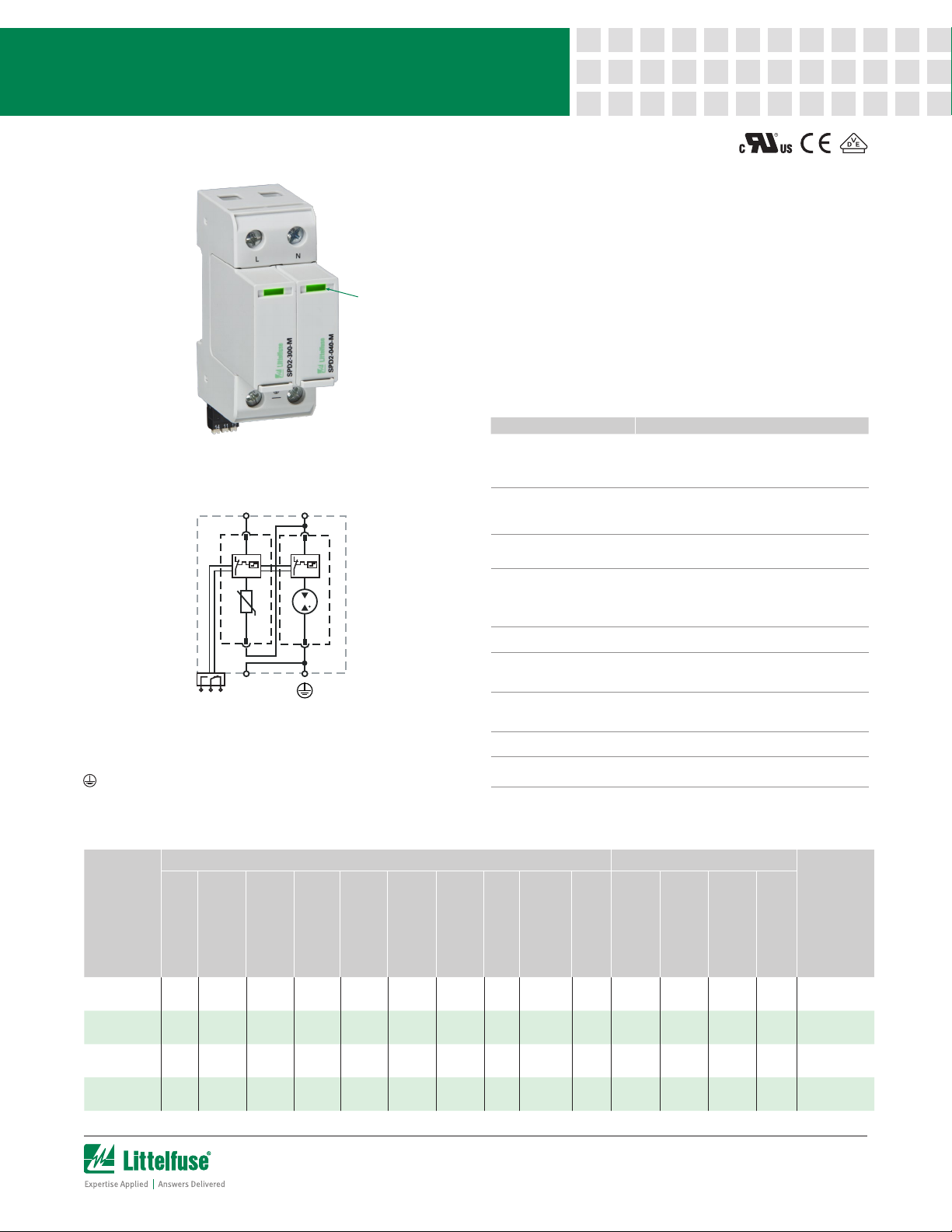
Visual Life
Indicator
Pluggable RC
Connector
Internal Configuration
L N
TD TD
RC
14 11 12
Legend
L Line
N Neutral
Protective Earth
RC Remote Contacts
TD Thermal Disconnection
Description
Surge protection devices (SPDs) provide equipment protection
from overvoltage events lasting micro-seconds. By limiting
the overvoltage to the equipment during these events, costly
equipment damage and downtime can be mitigated.
The surge protection devices for the 1+1 configuration are
available for 60 V to 277 V nominal voltage sub-distribution
board applications.
Features & Benefits
FEATURES BENEFITS
Capability to clamp and
withstand high-energy
transients
UL Recognized and
VDE-IEC compliant in
single part number
Interlocking tab
mechanism
No additional
overcurrent protection
devices required in
UL applications
Compact footprint
Visual life indicator
Pluggable modules
Thermal protection Eliminates catastrophic failure
IP20 protection rating Finger-safe design increases worker protection
Ensures low-residual voltage during high-energy
surge events and higher nominal discharge current
to prevent disruption, downtime, and degradation or
damage to equipment
One component can be utilized globally, reducing
inventory needs and simplifying allocation of parts
Secures module to withstand vibration
Reduces the number of components and costs
required for protection
I
ncreases panel design flexibility
Quick visual determines module replacement status
to avoid loss of protection
Fast and simple to replace, minimizing maintenance
and downtime. No tools required
Module & Base Ordering Information
IEC Electrical UL Electrical
)
)
max
(L-N / N-PE I
Voltage Protection
Level (L-N / N-PE U
800 V /
1500 V
1250 V /
1500 V
1500 V /
1500 V
1750 V /
1500 V
p
100 A
100 A
100 A
100 A
Ordering
Number
Nominal AC Voltage
SPD2-075-1P1-R 60 V
SPD2-150-1P1-R 120 V
SPD2-300-1P1-R 240 V
SPD2-350-1P1-R 277 V
)
n
/U
o
(50/60Hz) (U
Operating AC Voltage
Maximum Continuous
75 V /
305 V
150 V /
305 V
300 V /
305 V
350 V /
305 V
)
c
(L-N / N-PE U
Current (8/20 µs)
Nominal Discharge
20 kA /
40 kA
20 kA /
40 kA
20 kA /
40 kA
20 kA /
40 kA
)
n
(L-N / N-PE I
Current (8/20 µs)
Maximum Discharge
50 kA /
65 kA
50 kA /
65 kA
50 kA /
65 kA
50 kA /
65 kA
)
T
1200 V
1200 V
1200 V
1200 V
T
TOV Withstand
200 ms (N-PE U
AC Operating Voltage
Maximum Continuous
75 V /
305 V
150 V /
305 V
300 V /
305 V
350 V /
305 V
Rating
(L-N / N-PE VPR)
Voltage Protection
(L-N / N-PE MCOV)
330 V /
1000 V
600 V /
1000 V
900 V /
1000 V
1000 V /
1000 V
fi
Current Rating
Short-Circuit AC
25 kA /
50 kA
25 kA /
50 kA
25 kA /
50 kA
25 kA /
50 kA
)
SCCR
(L-N I
TOV Withstand
114 V
229 V
337 V
403 V
5 s (L-N U
TOV 120 min
114 V /
Withstand
229 V /
Withstand
442 V /
Safe Fail
529 V /
Safe Fail
) / Mode
(L-N U
)
(N-PE I
Follow Current
Interrupt Rating
RMS
RMS
RMS
RMS
)
T
)
n
(L-N / N-PE I
Current (8/20 µs)
Nominal Discharge
20 kA /
100 kA 124 g (0.274 lb)
20 kA
20 kA /
200 kA 128 g (0.283 lb)
20 kA
20 kA /
150 kA 135 g (0.298 lb)
20 kA
20 kA /
200 kA 140 g (0.309 lb)
20 kA
Single Unit
Weight
Rating (L-N SCCR)
Short-Circuit Current
1 of 2
Surge Protection Devices
SPD2 1P+1 SERIES
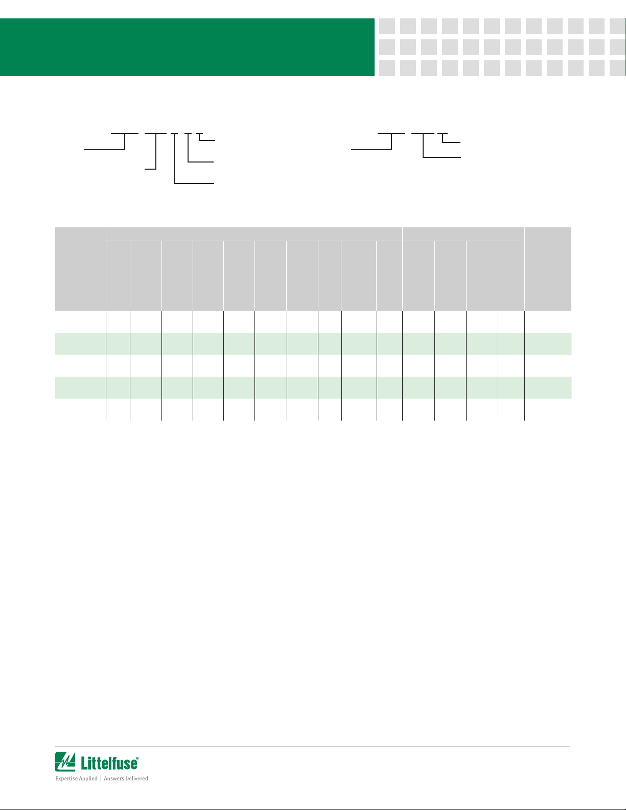
Module & Base Part Numbering System Module Only Part Numbering System
SPD2 VVV XPZ R
Series
Maximum Continuous
Operating AC Voltage
Optional Remote
Contact
Neutral
(1=yes or 0=no)
Number of Poles
Replacement Module Ordering Information
IEC Electrical UL Electrical
)
)
max
(L-N / N-PE I
Voltage Protection
Level (L-N / N-PE U
1500 V
(N-PE)
800 V /
1500 V
1250 V /
1500 V
1500 V /
1500 V
1750 V /
1500 V
p
)
fi
(N-PE I
Follow Current
Interrupt Rating
Short-Circuit AC
100 A
100 A
100 A
100 A
100 A
25 kA /
RMS
50 kA
25 kA /
RMS
50 kA
25 kA /
RMS
50 kA
25 kA /
RMS
50 kA
25 kA /
RMS
50 kA
Ordering
Number
Nominal AC Voltage
SPD2-040-M 0 V
SPD2-075-M 60 V
SPD2-150-M 120 V
SPD2-300-M 240 V
SPD2-350-M 277 V
)
n
/U
o
(50/60Hz) (U
Operating AC Voltage
Maximum Continuous
40 V /
305 V
75 V /
305 V
150 V /
305 V
300 V /
305 V
350 V /
305 V
)
c
(L-N / N-PE U
Current (8/20 µs)
Nominal Discharge
20 kA /
40 kA
20 kA /
40 kA
20 kA /
40 kA
20 kA /
40 kA
20 kA /
40 kA
)
n
(L-N / N-PE I
Current (8/20 µs)
Maximum Discharge
50 kA /
65 kA
50 kA /
65 kA
50 kA /
65 kA
50 kA /
65 kA
50 kA /
65 kA
Series
)
T
)
SCCR
(L-N I
Current Rating
5 s (L-N U
TOV Withstand
N/A N/A 1200 V
114 V /
114 V
Withstand
229 V /
229 V
Withstand
442 V /
337 V
Safe Fail
529 V /
403 V
Safe Fail
SPD2 VVV M
)
) / Mode
T
TOV 120 min
TOV Withstand
(L-N U
200 ms (N-PE U
1200 V
1200 V
1200 V
1200 V
T
(L-N / N-PE MCOV)
AC Operating Voltage
Maximum Continuous
305 V
(N-PE)
75 V /
305 V
150 V /
305 V
300 V /
305 V
350 V /
1000 V /
305 V
Module Only
Maximum Continuous
Operating AC Voltage
)
n
Rating
Voltage Protection
1000 V
(N-PE)
330 V /
1000 V
600 V /
1000 V
900 V /
1000 V
1000 V
(L-N / N-PE VPR)
Current (8/20 µs)
Nominal Discharge
20 kA /
20 kA
20 kA /
20 kA
20 kA /
20 kA
20 kA /
20 kA
20 kA /
20 kA
(L-N / N-PE I
Single Unit
Weight
Rating (L-N SCCR)
Short-Circuit Current
N/A 42 g (0.093 lb)
100 kA 50 g (0.111 lb)
200 kA 54 g (0.120 lb)
150 kA 61 g (0.135 lb)
200 kA 68 g (0.146 lb)
Specifications
Network Systems IT, T T, TN -S
Mode of Protection L-N, N - PE
Nominal Discharge Current
(8/20 µs) (L-N / N-PE I
) 20 kA/40 kA
n
Maximum Discharge Current
(8/2 0 µs) (L-N / N-PE I
) 50 kA/65 kA
max
Protective Elements High Energy MOV and GDT
Response Time
(L-N / N-PE tA) < 25 ns
Back-Up Fuse (max) 315 A / 250 A Gg
Number of Ports
1
Mechanical & Environmental
Operating Temperature
Range (Ta) -40 °C to +80 °C (-40 °F to +185 °F)
Permissible Operating
Humidity (RH) 5% to 95%
Altitude (max) 4,000 m (13,123 ft)
Terminal Screw Torque) (M
) 4.5 Nm (39.9 lbf-in)
max
Conductor Cross Section (max) 35 mm² (2 AWG) (Solid, Stranded)/
25 mm2 (4 AWG) (Flexible)
Mounting 35 mm DIN Rail, EN60715
Degree of Protection IP20 (built-in)
Warranty – Visit www.littelfuse.com/warranty for details.
Disclaimer Notice – Information furnished is believed to be accurate and reliable. However, users should independently evaluate the suitability of and test each product selected for their own applications. Littelfuse
products are not designed for, and may not be used in, all applications. Read complete Disclaimer Notice at www.littelfuse.com/product-disclaimer.
Housing Material Thermoplastic: Extinguishing Degree
UL 94 V-0
Thermal Protection Yes
Operating State/Fault
Indication Green Flag/No Green Flag
Remote Contact Switching
Capacity AC: 250 V/1 A, 125 V/1 A;
DC: 48 V/0.5 A, 24 V/0.5 A, 12 V/0.5 A
Remote Contact Conductor
Cross Section (max) 1.5 mm2 (16 AWG) (Solid)
Standards Passed IE C 616 4 3 -11: 2 0 11
EN 61643-11:2012
UL 1449, 4th edition; E320116
Product Dimensions
2TE Module and Base H 90.0 mm (3.54”); W 36.0 mm (1.42”);
D 70.0 mm (2.76”)
1TE Replacement Module H 45.0 mm (1.77”); W 18.0 mm (0.71”);
D 57.2mm (2.25”)
Package Dimensions
2TE Module and Base
H 102.0 mm (4.01”); W 46.0 mm (1.81”);
D 110.0 mm (4.33”)
1TE Replacement Module
H 102.0 mm (4.01”); W 28.0 mm (1.10”);
D 110.0 mm (4.33”)
2 of 2
 Loading...