

Page 1
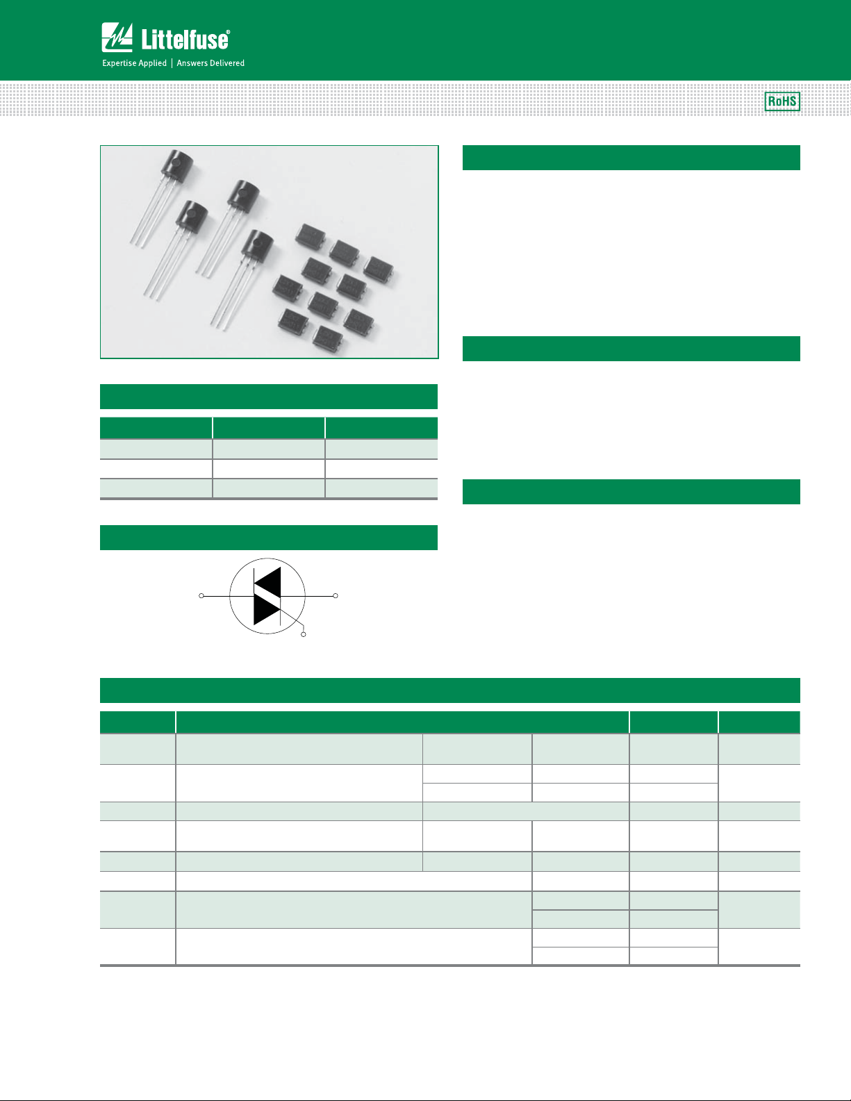
Teccor® brand Thyristors
1 Amp Sensitive & Standard Triacs
Lx01Ex & LxNx & Qx01Ex & QxNx Series
Description
1 Amp bi-directional solid state switch series is designed
for AC switching and phase control applications such as
motor speed and temperature modulation controls, lighting
controls, and static switching relays.
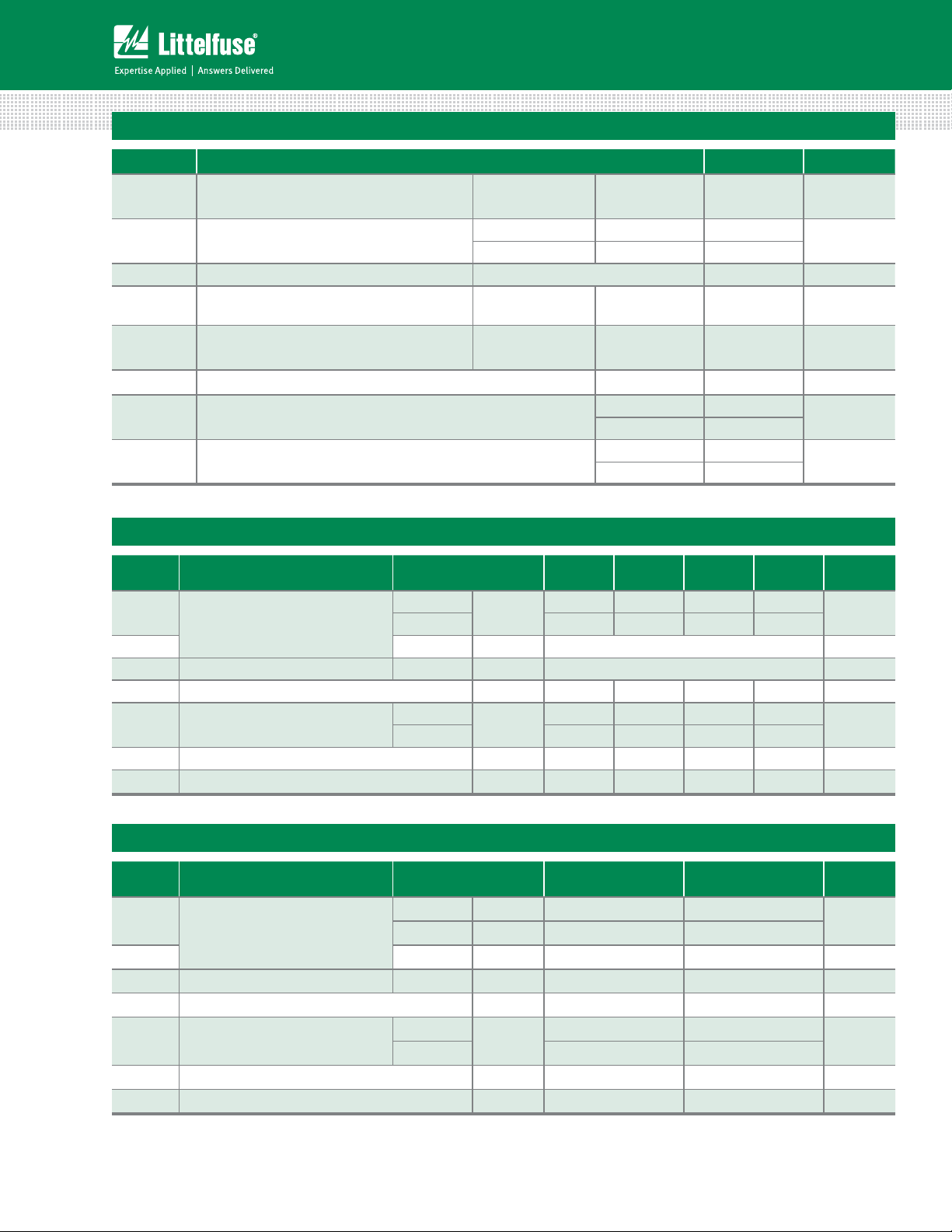
Sensitive type devices guarantee gate control in Quadrants
I & IV needed for digital control circuitry.
Standard type devices normally operate in Quadrants I & III
triggered from AC line.
Features & Benefits
Main Features
t3P)4$PNQMJBOU
t(MBTToQBTTJWBUFE
t4VSHFDBQBCJMJUZVQUP
20 A
junctions
Symbol Value Unit
I
T(RMS)
V
DRM/VRRM
I
GT (Q1)
1A
400 to 600 V
3 to 25 mA
t7PMUBHFDBQBCJMJUZVQUP
600 V
Applications
Excellent for lower current heating controls, water valves,
Schematic Symbol
and solenoids.
Typical applications are AC solid-state switches, home/
brown goods and white goods appliances.
MT2 MT1
Sensitive gate Triacs can be directly driven by
microprocessor or popular opto-couplers/isolators.
G
Absolute Maximum Ratings — Sensitive Triacs (4 Quadrants)
Symbol Parameter Value Unit
I
T(RMS)
I
TSM
2
I
tI
Non repetitive surge peak on-state current
di/dt
I
GTM
P
G(AV)
T
stg
T
J
Note: x = voltage, y = sensitivity
RMS on-state current
(full sine wave)
(full cycle, TJ initial = 25°C)
2
t Value for fusing tp = 8.3 ms 1.6 A2s
Critical rate of rise of on-state current
= 50mA with 0.1s rise time)
(I
G
Peak gate trigger current tp 10 s
Average gate power dissipation
Storage temperature range
Operating junction temperature range
Lx01Ey/LxNy T
f = 50 Hz t = 20 ms 16.7
f = 60 Hz t = 16.7 ms 20
f = 120 Hz
= 50°C 1 A
C
= 110°C
T
J
T
= 110°C
J
T
= 110°C
J
20 A/s
1A
0.2 W
Lx01Ey -65 to 150
LxNy -40 to 125
Lx01Ey -65 to 110
LxNy -40 to 110
A
°C
°C
Lx01Ex & LxNx & Qx01Ex & QxNx Series
35
Specifications are subject to change without notice.
©2013 Littelfuse, Inc
Revised: 09/23/13
Page 2
Teccor® brand Thyristors
1 Amp Sensitive & Standard Triacs
Absolute Maximum Ratings — Standard Triacs
Symbol Parameter Value Unit
I
T(RMS)
I
TSM
2
tI
I
Non repetitive surge peak on-state current
di/dt
I
GTM
P
G(AV)
T
stg
T
J
Note: x = voltage, y = sensitivity
Electrical Characteristics (T
Symbol Test Conditions Quadrant
I
GT
V
GT
V
GD
I
H
dv/dt VD = V
VD = 12V RL = 60
VD = V
DRM
IT = 100mA MAX. 5 10 10 15 mA
DRM
RMS on-state current
(full sine wave)
Qx01Ey/QxNy T
= 60°C 1 A
C
f = 50 Hz t = 20 ms 16.7
(full cycle, TJ initial = 25°C)
2
t Value for fusing tp = 8.3 ms 1.6 A2s
Critical rate of rise of on-state current
= 200mA with 0.1s rise time)
(I
G
Peak gate trigger current
Average gate power dissipation
Storage temperature range
Operating junction temperature range
= 25°C, unless otherwise specified) — Sensitive Triac (4 Quadrants)
J
*o**o***
IV 3 5 10 20
f = 60 Hz t = 16.7 ms 20
f = 120 Hz
10 s;
t
p
IGT I
GTM
= 125°C
T
J
T
= 125°C
J
T
= 125°C
J
Qx01Ey -65 to 150
QxNy -40 to 150
Qx01Ey -65 to 125
QxNy -40 to 125
MAX.
Lx01E3
LxN3
35510
Lx01E5
LxN5
Lx01E6
LxN6
20 A/s
1A
0.2 W
Lx01E8
LxN8
ALL MAX. 1.3 V
RL = 3.3 k TJ = 110°C ALL MIN. 0.2 V
Gate Open TJ = 100°C
400V
600V 10 10 20 25
TYP.
20 20 30 35
(dv/dt)c (di/dt)c = 0.54 A/ms TJ = 110°C TYP. 0.5 1 1 1 V/s
t
gt
IG = 2 x IGT PW = 15s IT = 1.41 A(pk) TYP. 2.8 3.0 3.0 3.2 s
A
°C
°C
Unit
mA
V/s
Electrical Characteristics (T
Symbol Test Conditions Quadrant
I
GT
V
GT
V
GD
I
H
dv/dt VD = V
VD = 12V RL = 60
VD = V
RL = 3.3 k TJ = 125°C ALL MIN. 0.2 0.2 V
DRM
IT = 200mA MAX. 15 25 mA
Gate Open TJ = 125°C
DRM
= 25°C, unless otherwise specified) — Standard Triac
J
*o**o*** MAX. 10 25
IV TYP. 25 50
*o**o*** MAX. 1.3 1.3 V
400V
600V 20 30
MIN.
Qx01E3
QxN3
30 40
Qx01E4
QxN4
(dv/dt)c (di/dt)c = 0.54 A/ms TJ = 125°C TYP. 1 1 V/s
t
gt
Note: x = voltage, y = sensitivity
Lx01Ex & LxNx & Qx01Ex & QxNx Series
IG = 2 x IGT PW = 15s IT = 1.41 A(pk) TYP. 2.5 3.0 s
36
Specifications are subject to change without notice.
©2013 Littelfuse, Inc
Unit
mA
V/s
Revised: 09/23/13
Page 3
Teccor® brand Thyristors
1 Amp Sensitive & Standard Triacs
Static Characteristics (T
= 25°C, unless otherwise specified)
J
Symbol Test Conditions Value Unit
V
I
I
TM
DRM
RRM
ITM = 1.41A tp = 380 µs MAX. 1.60 V
T
= 25°C 400-600V 2 A
Lx01Ey / LxNy
V
DRM
= V
RRM
MAX.
Qx01Ey / QxNy
J
= 110°C 400-600V 0.1 mA
T
J
= 25°C 400-600V 5 A
T
J
= 125°C 400-600V 1 mA
T
J
Thermal Resistances
Symbol Parameter Value Unit
R
(J-C)
R
(J-A)
Note: * = Mounted on 1 cm2 copper (two-ounce) foil surface
Junction to case (AC)
Junction to ambient L/Qx01Ey 95 °C/W
Figure 1: Definition of Quadrants
ALL POLARITIES ARE REFERENCED TO MT1
MT2 POSITIVE
(Positive Half Cycle)
MT2
(-)
I
GT
GATE
MT1
I
GT
GATE
REF
MT2
MT1
REF
I
-
GT
(-)
+
(+)
I
GATE
QII
QI
QIV
QIII
(+)
I
GT
GATE
-
MT2 NEGATIVE
(Negative Half Cycle)
GT
MT2
REF
MT2
REF
MT1
MT1
+ I
GT
L/Qx01Ey 50
L/QxNy 40
*
°C/W
Figure 2: Normalized DC Gate Trigger Current for
All Quadrants vs. Junction Temperature
4.0
3.0
=25ºC)
j
(T
GT
/I
2.0
GT
1.0
Ratio of I
0.0
-65 -40 -15 10 35 60 85 110 125
Junction Temperature (Tj) - ºC
Lx01Ex & LxNx & Qx01Ex & QxNx Series
37
Specifications are subject to change without notice.
©2013 Littelfuse, Inc
Revised: 09/23/13
Page 4

Teccor® brand Thyristors
1 Amp Sensitive & Standard Triacs
Figure 3: Normalized DC Holding Current
vs. Junction Temperature
4.0
3.0
= 25ºC)
j
(T
H
2.0
/ I
H
1.0
Ratio of I
0.0
-65 -40 -15 10 35 60 85 110 125
Junction Temperature (Tj) - ºC
Figure 5: Power Dissipation (Typical)
vs. RMS On-State Current
1.5
CURRENT WAVE FORM: Sinusoidal
LOAD: Resistive or Inductive
) - Watts
1.0
D(AV)
0.5
Average On-State
Power Dissipation (P
0.0
CONDUCTION ANGLE: 360°
RMS On-State Current (I
T(RMS)
) - Amps
Figure 4: Normalized DC Gate Trigger Voltage for
All Quadrants vs. Junction Temperature
2.0
1.5
= 25ºC)
j
(T
GT
1.0
/V
GT
0.5
Ratio of V
0.0
-65 -40 -15 10 35 60 85 110 125
Junction Temperature (Tj) - ºC
Figure 6: Maximum Allowable Case Temperature
vs. On-State Current
130
) - ºC
120
C
110
100
90
Lx01Ex / LxNx
80
70
60
Max Allowable Case Temperature (T
1.251.00.5 0.750.250
50
0 0.2 0.4 0.6 0.8 1 1.2
RMS On-State Current [I
CURRENT WAVE FORM: Sinusoidal
LOAD: Resistive or Inductive
CONDUCTION ANGLE: 360º
CASE TEMPERATURE: Measured as shown
on Dimensional Drawing
Qx01Ex /QxNx
] - AMPS
T(RMS)
Figure 7: Maximum Allowable Ambient Temperature
vs. On-State Current
120
CURRENT WAVEFORM: Sinusoidal
LOAD: Resistive or Inductive
100
80
) - ºC
A
(T
60
40
Max Allowable Ambient Temperature
20
0.0 0.1 0.2 0.3 0.4 0.5 0.6 0.7
RMS On-State Current [I
Lx01Ex & LxNx & Qx01Ex & QxNx Series
CONDUCTION ANGLE: 360º
FREE AIR RATING - NO HEATSINK
] - AMPS
T(RMS)
Figure 8: On-State Current vs. On-State Voltage
(Typical)
8
7
6
) - AMPS
5
T
4
3
2
On-State Current (I
1
Positive or Negative Instantaneous
0
0.6 0.8 1.0 1.2 1.4 1.6 1.8
Positive or Negative Instantaneous On-State Voltage
38
TC = 25ºC
(V
) - Volts
T
Specifications are subject to change without notice.
©2013 Littelfuse, Inc
Revised: 09/23/13
Page 5

Teccor® brand Thyristors
eat
Ramp-do
1 Amp Sensitive & Standard Triacs
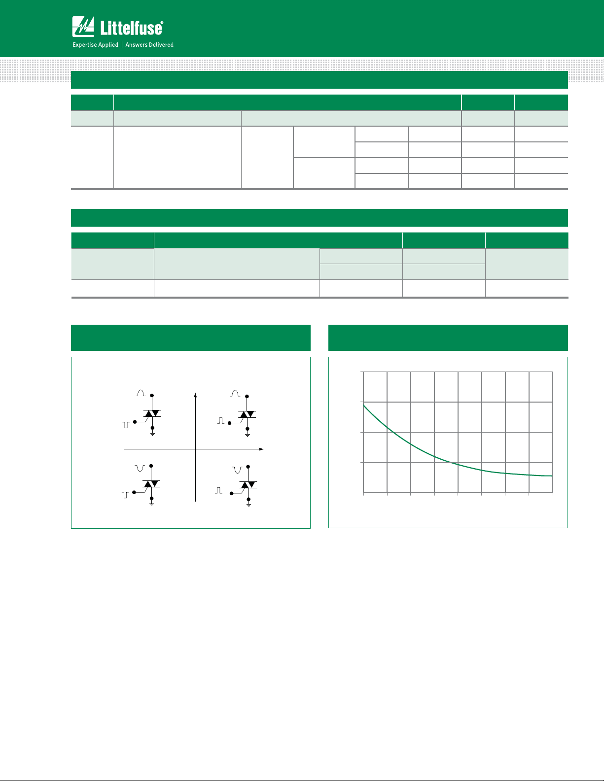
Figure 9: Surge Peak On-State Current vs. Number of Cycles
100
10
) – Amps
TSM
(I
Peak Surge (Non-repetitive) On-State Current
1
1 10 100 1000
Surge Current Duration – Full Cycles
Soldering Parameters
Reflow Condition 1Co'SFFBTTFNCMZ
- Temperature Min (T
Pre Heat
- Temperature Max (T
- Time (min to max) (ts) oTFDT
Average ramp up rate (Liquidus Temp)
(TL) to peak
T
to TL - Ramp-up Rate 5°C/second max
S(max)
Reflow
- Temperature (TL) (Liquidus) 217°C
- Temperature (tL) oTFDPOET
Peak Temperature (TP) 260°C
Time within 5°C of actual peak
Temperature (tp)
Ramp-down Rate 5°C/second max
Time 25°C to peak Temperature (TP) 8 minutes Max.
Do not exceed 280°C
) 150°C
s(min)
) 200°C
s(max)
5°C/second max
oTFDPOET
T
P
T
L
T
S(max)
Temperature
T
S(min)
25
Supply Frequency: 60Hz Sinusoidal
Load: Resistive
RMS On-State [I
Specific Case Temperature
Notes:
1. Gate control may be lost during and immediately
following surge current interval.
2. Overload may not be repeated until junction
temperature has returned to steady-state
rated value.
t
S
time to peak temperature
]: Max Rated Value at
T(RMS)
Ramp-upRamp-up
PreheatPreh
t
P
t
L
Ramp-down
Time
Lx01Ex & LxNx & Qx01Ex & QxNx Series
39
Specifications are subject to change without notice.
©2013 Littelfuse, Inc
Revised: 09/23/13
Page 6

Teccor® brand Thyristors
1 Amp Sensitive & Standard Triacs
Physical Specifications
Terminal Finish 100% Matte Tin-plated
Body Material
UL recognized epoxy meeting flammability
classification 94V-0
Terminal Material Copper Alloy
Design Considerations
Careful selection of the correct device for the application’s
operating parameters and environment will go a long way
toward extending the operating life of the Thyristor. Good
design practice should limit the maximum continuous
current through the main terminals to 75% of the device
rating. Other ways to ensure long life for a power discrete
semiconductor are proper heat sinking and selection of
voltage ratings for worst case conditions. Overheating,
overvoltage (including dv/dt), and surge currents are
the main killers of semiconductors. Correct mounting,
soldering, and forming of the leads also help protect
against component damage.
Environmental Specifications
Test
AC Blocking
Temperature Cycling
Temperature/
Humidity
High Temp Storage
Low-Temp Storage 1008 hours; -40°C
Thermal Shock
Autoclave
Resistance to
Solder Heat
Solderability ANSI/J-STD-002, category 3, Test A
Lead Bend MIL-STD-750, M-2036 Cond E
Specifications and Conditions
MIL-STD-750, M-1040, Cond A Applied
Peak AC voltage @ 125°C for 1008 hours
MIL-STD-750, M-1051,
100 cycles; -40°C to +150°C; 15-min
dwell time
EIA / JEDEC, JESD22-A101
1008 hours; 320V - DC: 85°C; 85%
rel humidity
MIL-STD-750, M-1031,
1008 hours; 150°C
MIL-STD-750, M-1056
10 cycles; 0°C to 100°C; 5-min dwell
time at each temperature; 10 sec (max)
transfer time between temperature
EIA / JEDEC, JESD22-A102
168 hours (121°C at 2 ATMs) and
100% R/H
MIL-STD-750 Method 2031
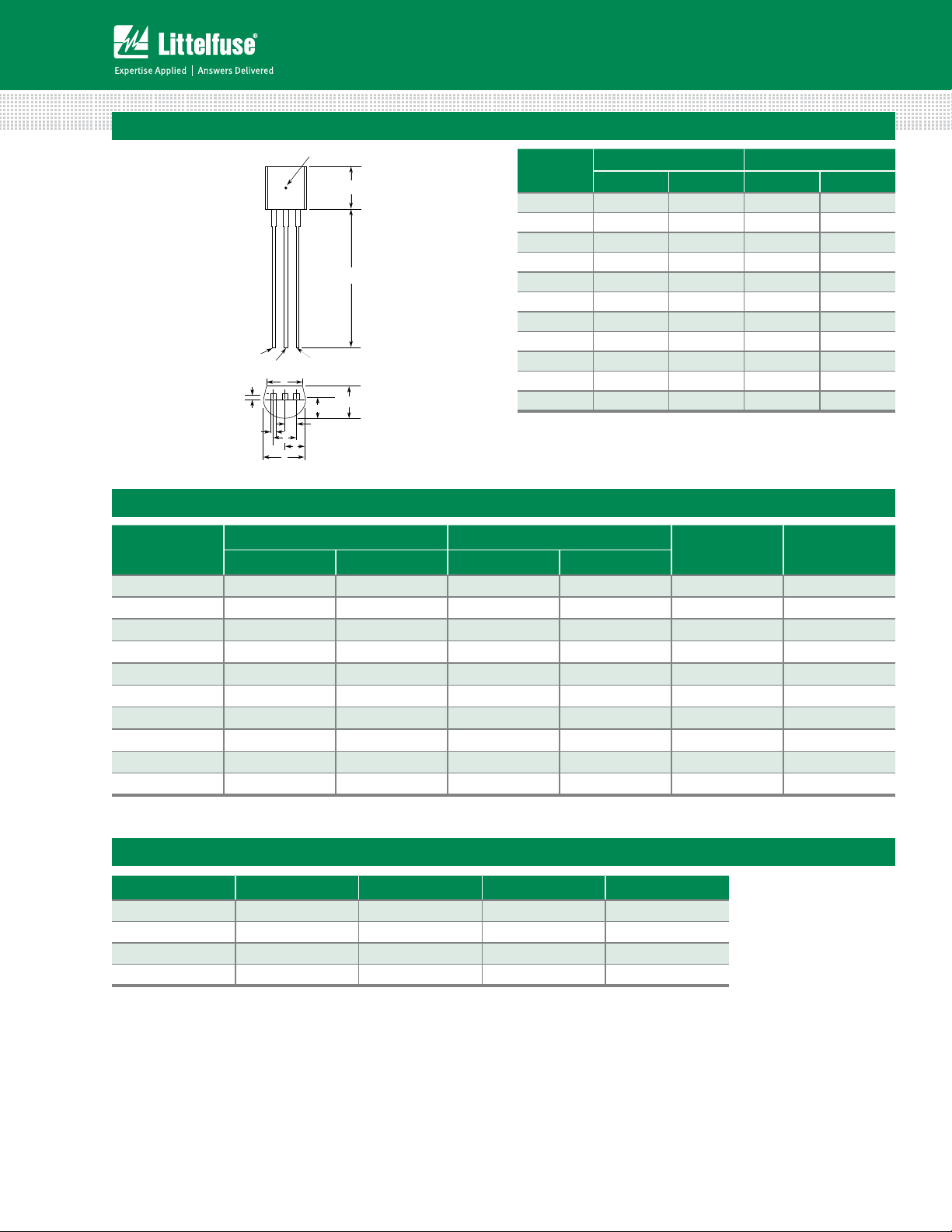
Dimensions - Compak (C Package)
TC / TL Temperature
Measurement Point
0.110
(2.8)
A
MT2
C
0.079
(2.0)
B
D
JE
K
0.079
(2.0)
Pad Outline
H
0.079
(2.0)
Gate
M
N
P
Dimension
A
B 0.201 0.220 5.10 5.60
Inches Millimeters
Min Max Min Max
0.130 0.156 3.30 3.95
C 0.077 0.087 1.95 2.20
D 0.159 0.181 4.05 4.60
MT1
E 0.030 0.063 0.75 1.60
F 0.075 0.096 1.90 2.45
G 0.002 0.008 0.05 0.20
F
L
H 0.077 0.104 1.95 2.65
J 0.043 0.053 1.09 1.35
G
K 0.006 0.016 0.15 0.41
L 0.030 0.055 0.76 1.40
M 0.022 0.028 0.56 0.71
0.040
(1.0)
0.030
(0.76)
Dimensions are in inches
(and millimeters).
N 0.027 0.033 0.69 0.84
P 0.052 0.058 1.32 1.47
Lx01Ex & LxNx & Qx01Ex & QxNx Series
40
Specifications are subject to change without notice.
©2013 Littelfuse, Inc
Revised: 09/23/13
Page 7
Dimensions - TO-92 (E Package)
TC Measuring Point
MT1
Gate
M
L
MT2
E
H
F
D
K
J
Teccor® brand Thyristors
1 Amp Sensitive & Standard Triacs
Dimension
A
A 0.176 0.196 4.47 4.98
B 0.500 - 12.70 D 0.095 0.105 2.41 2.67
B
G
E 0.150 - 3.81 -
F 0.046 0.054 1.16 1.37
G 0.135 0.145 3.43 3.68
H 0.088 0.096 2.23 2.44
J 0.176 0.186 4.47 4.73
K 0.088 0.096 2.23 2.44
L 0.013 0.019 0.33 0.48
M 0.013 0.017 0.33 0.43
All leads insulated from case. Case is electrically nonconductive.
Inches Millimeters
Min Max Min Max
Product Selector
Part Number
400V 600V I – II – III IV
Lx01E3 X X 3 mA 3 mA Sensitive Triac TO-92
LxN3 X X 3 mA 3 mA Sensitive Triac Compak
Lx01E5 X X 5 mA 5 mA Sensitive Triac TO-92
LxN5 X X 5 mA 5 mA Sensitive Triac Compak
Lx01E6 X X 5 mA 10 mA Sensitive Triac TO-92
Lx01E8 X X 10 mA 20 mA Sensitive Triac TO-92
Qx01E3 X X 10 mA Standard Triac TO-92
QxN3 X X 10 mA Standard Triac Compak
Qx01E4 X X 25 mA Standard Triac TO-92
QxN4 X X 25 mA Standard Triac Compak
Note: x- voltage
Voltage Gate Sensitivity Quadrants
Type Package
Packing Options
Part Number Marking Weight Packing Mode Base Quantity
L/Qx01Ey L/Qx01Ey 0.188 g Bulk 2000
L/Qx01EyRP L/Qx01Ey 0.188 g Reel Pack 2000
L/Qx01EyAP L/Qx01Ey 0.188 g Ammo Pack 2000
L/QxNyRP L/QxNy 0.081 g Embossed Carrier 2500
Note: x = Voltage; y = Sensitivity
Lx01Ex & LxNx & Qx01Ex & QxNx Series
41
Specifications are subject to change without notice.
©2013 Littelfuse, Inc
Revised: 09/23/13
Page 8

Teccor® brand Thyristors
1 Amp Sensitive & Standard Triacs
TO-92 (3-lead) Reel Pack (RP) Radial Leaded
Meets all EIA-468-C Standards
0.02 (0.5)
0.236
(6.0)
1.6
(41.0)
0.708
(18.0)
0.354
(9.0)
(50.0)
1.97
0.5
(12.7)
0.1 (2.54)
14.17(360.0)
MT1
0.2 (5.08)
Gate
Direction of Feed
MT2
0.098 (2.5) MAX
Flat up
Dimensions
are in inches
(and millimeters).
0.157
(4.0)
1.26
(32.0)
DIA
TO-92 (3-lead) Ammo Pack (AP) Radial Leaded
Meets all EIA-468-C Standards
0.02 (0.5)
0.236
(6.0)
1.62
(41.2)
0.708
(18.0)
0.354
(9.0)
0.5
(12.7)
Direction of Feed
0.1 (2.54)
13.3
(338.0)
0.2 (5.08)
MT2
MT1
Gate
25 Devices per fold
0.098 (2.5) MAX
Flat down
1.85
(47.0)
12.2
(310.0)
1.85
(47.0)
0.157
DIA
(4.0)
Dimensions
are in inches
(and millimeters).
1.27
(32.2)
Lx01Ex & LxNx & Qx01Ex & QxNx Series
42
Specifications are subject to change without notice.
©2013 Littelfuse, Inc
Revised: 09/23/13
Page 9
Teccor® brand Thyristors
1 Amp Sensitive & Standard Triacs
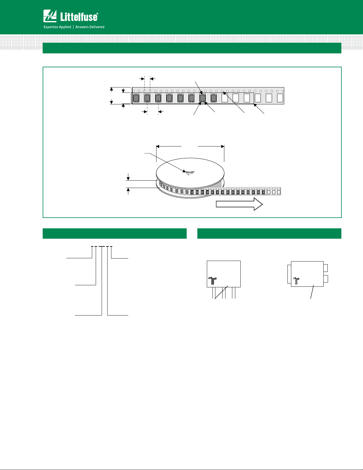
Compak Embossed Carrier Reel Pack (RP)
Meets all EIA-481-1 Standards
DEVICE TYPE
L : Sensitive Triac
Q : Triac
VOLTAGE RATING
4 : 400V
6 : 600V
CURRENT RATING
01 : 1.0A (TO-92)
N : 1.0A (Compak)
0.47
(12.0)
L 4 01 E 3
0.157
(4.0)
0.36
(9.2)
0.512 (13.0) Arbor
Hole Dia.
0.49
(12.4)
SENSITIVITY & TYPE
Sensitive Triac:
3 : 3 mA (QI, II, III, IV)
5 : 5 mA (QI, II, III, IV)
6 : 5 mA (QI, II, III)
10 mA (QIV)
8 : 10 mA (QI, II, III)
20 mA (QIV)
Standard Triac:
3 : 10 mA (QI, II, III)
4 : 25 mA (QI, II, III)
PACKAGE TYPE
Blank : Compak (Surface Mount)
E : TO-92
0.315
(8.0)
8.0
MT2
MT1
12.99
(330.0)
Gate
Part Marking SystemPart Numbering System
TO-92 (E Package)
L401E3
®
Date Code Marking
Y:Year Code
M: Month Code
L: Location Code
XX: Lot Serial Code
0.059
(1.5)
Direction of Feed
YMLXX
Cover tape
DIA
Dimensions
are in inches
(and millimeters).
Compak (C Package)
L4N3
YMXXX
®
Date Code Marking
Y:Year Code
M: Month Code
XXX: Lot Trace Code
Lx01Ex & LxNx & Qx01Ex & QxNx Series
43
Specifications are subject to change without notice.
©2013 Littelfuse, Inc
Revised: 09/23/13
 Loading...