

Littelfuse Q6012LH1LED User Manual
Teccor® brand Thyristors
MT1
12 Amp Alternistor (High Communitation) Triac for LED dimmer Application
Q6012LH1LED Series
Agency Approval
Agency Agency File Number
®
Main Features
Symbol Value Unit
I
T(RMS)
V
DRM/VRRM
I
GT
Schematic Symbol
L Package: E71639
12 A
600 V
10 mA
RoHS
Description
Q6012LH1LED series is designed to meet low load current
characteristics typical in LED lighting applications.
By keeping holding current at 8mA maximum, this Triac
series is characterized and specified to perform best with
LED loads. The Q6008LH1LED series is best suited for LED
dimming controls to obtain the lowest levels of light output
with a minimum probability of flickering.
Q6012LH1LED series is offered in the industry standard
TO-220AB package with an isolated mounting tab that
makes it best suited for adding an external heat sink.
Features
• As low as 8mA max
holding current
Benefits
• Provides full control
of light out put at the
extreme low end of load
conditions.
• UL recognized TO-220AB
package
• 2500V
min isolation
AC
between mounting tab
and active terminals
• 110
°C rated junction
temperature
• Improves margin of safe
operation with less heat
sinking required
• di/dt performance of
70A/
μs
• Enable survivability
of typically LED load
operating characteristics
• QUADRAC version
includes intergrated DIAC
• Simplicity of circuit design
& layout
MT2
Q6012LH1LED series
Applications
G
Excellent for AC switching and phase control applications
such as heating, lighting, and motor speed controls.
Typical applications are AC solid-state switches,lighting
controls with LED lamp loads, small low current motor in
power tools, lower current motor in home/brown goods
appliances.
Internally constructed isolated packages are offered for
ease of heat sinking with highest isolation voltage.
1
Revised: January 25, 2013 08:34 AM
Please refer to http://www.littelfuse.com for current information.
Specifications are subject to change without notice.
©2013 Littelfuse, Inc
Teccor® brand Thyristors
12 Amp Alternistor (High Communitation) Triac for LED dimmer Application
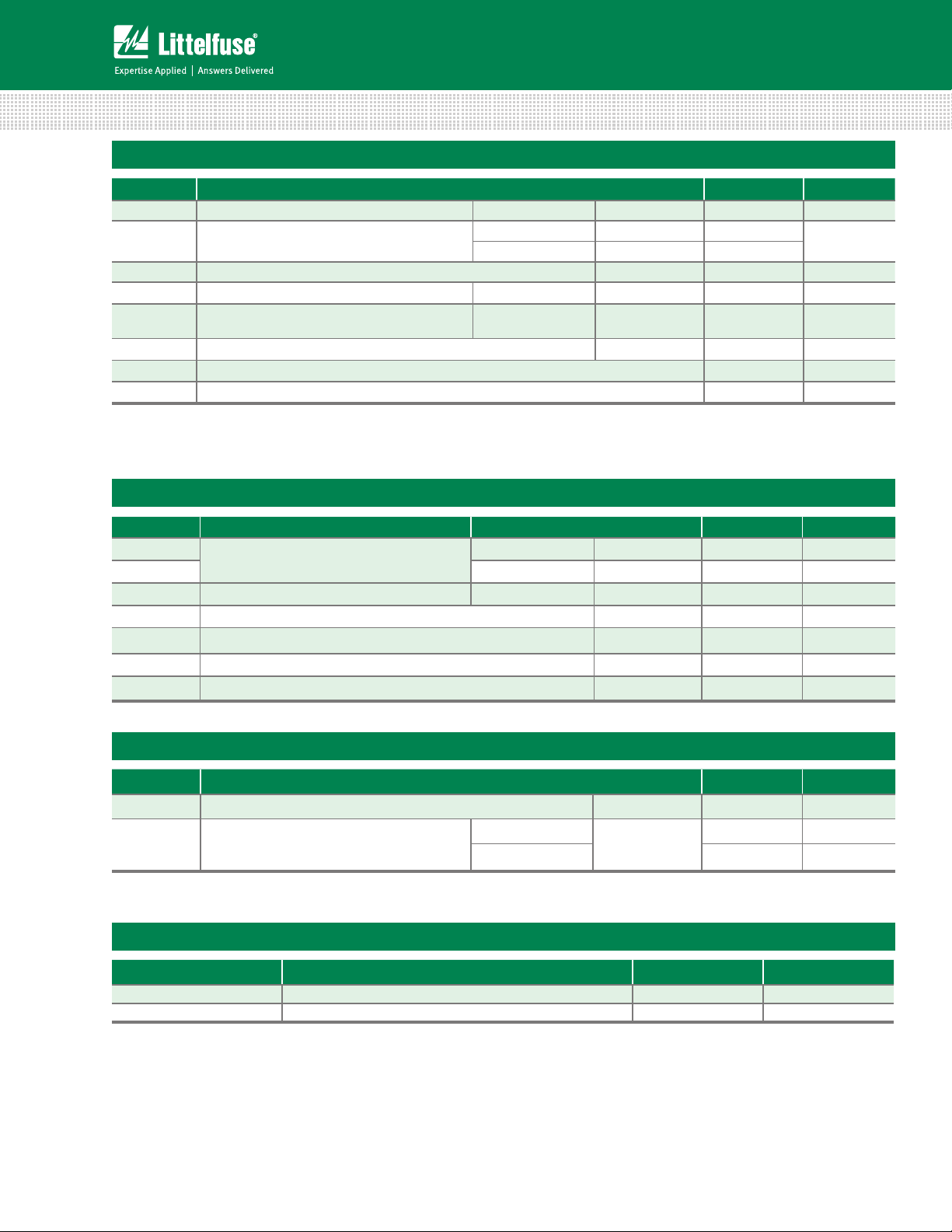
Absolute Maximum Ratings
Symbol Parameter Value Unit
I
T(RMS)
I
TSM
2
t I2t Value for fusing tp = 8.3 ms 60 A2s
I
di/dt Critical rate of rise of on-state current f = 120 Hz
I
GTM
P
G(AV)
T
stg
T
J
RMS on-state current (full sine wave) TC = 90°C 12 A
Non repetitive surge peak on-state current
(full cycle, TJ initial = 25°C)
Peak gate trigger current
Average gate power dissipation
f = 50 Hz t = 20 ms 110
f = 60 Hz t = 16.7 ms 120
= 110°C
T
J
t
≤ 10 μs;
p
IGT ≤ I
GTM
= 110°C
T
J
T
= 110°C
J
2.0 A
0.5 W
70 A/μs
Storage temperature range -40 to 150 °C
Operating junction temperature range -40 to 110 °C
A
Electrical Characteristics (T
= 25°C, unless otherwise specified)
J
Symbol Test Conditions Quadrant Qxx12LH1 Unit
I
GT
V
GT
V
GD
I
H
dv/dt V
VD = 12V RL = 60 Ω
VD = V
RL = 3.3 kΩ TJ = 110°C
DRM
IT = 20mA MAX. 8 mA
= V
Gate Open TJ = 110°C MIN. 45 V/μs
D
DRM
(dv/dt)c (di/dt)c = 6.5 A/ms T
t
gt
IG = 2 x IGT PW = 15μs IT = 17.0 A(pk) TYP. 4 μs
= 110°C MIN. 2 V/μs
J
I – II – III MAX. 10 mA
I – II – III MAX. 1. 3 V
I – II – III MIN. 0.2 V
Static Characteristics
Symbol Test Conditions Value Unit
V
I
I
TM
DRM
RRM
ITM = 17.0A tp = 380 µs MAX. 1.60 V
VD = V
DRM
/ V
RRM
TJ = 25°C
MAX.
T
= 110°C 1 mA
J
10 μA
Thermal Resistances
Symbol Parameter Value Unit
R
θ(J-C)
R
θ(J-A)
Q6012LH1LED series
Junction to case (AC) 2.3 °C/W
Junction to ambient (AC) 55 °C/W
2
Revised: January 25, 2013 08:34 AM
Please refer to http://www.littelfuse.com for current information.
Specifications are subject to change without notice.
©2013 Littelfuse, Inc
 Loading...