

Page 1
307
www.littelfuse.com
6
SILICON DIODE
ARRAYS
Silicon Avalanche Diodes
1500 Watt Axial Leaded Transient Voltage Suppressors
The ICTE/MPTE series 1500 W transient suppressors are designed
specifically for protection of CMOS, NMOS, BiMOS, and other
integrated circuits available today for TTL, DTL, ECL, RTL, and
linear functions. This series offers the lowest clamping voltages.
FEATURES
• Stand-off voltage range 5 to 45 Volts
• Uni-directional and Bi-directional
• Glass passivated junction
• Very low clamping voltages
• 100% surge tested
MAXIMUM RATING
• Peak Pulse Power (Ppk): 1500 Watts (10 x 1000µs) @25°C
(see diagram on page 3 for wave form)
• 5 watt steady state
• Response time: 1 x 10
-12
seconds (theoretical)
• Forward surge rating 200 Amps, 8.3ms half sine wave, (uni-
directional devices only)
• Operating & storage temperature: -55°C to +150°C
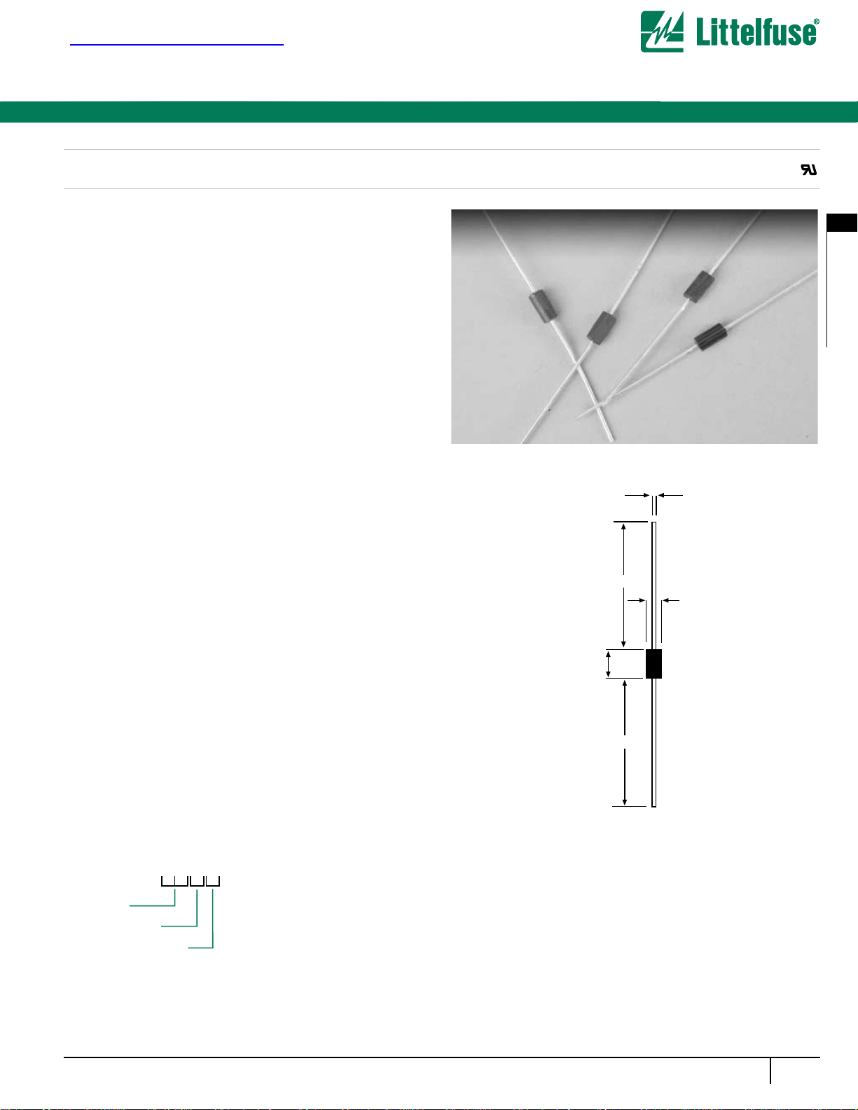
MECHANICAL CHARACTERISTICS
• Case: DO-201AD: Molded plastic over glass
passivated junction
• Terminals: Axial leads, solderable per MIL-STD-202
Method 208
• Solderable leads = 230°C for 10 seconds (1.59mm from case)
• Marking: cathode band, (positive terminal, uni-directional
devices only), device code, logo
• Weight: 1.5 grammes (approx)
Agency Approvals: Recognized under the Components
Program of Underwriters Laboratories.
Agency File Number: E128662
Max 1.066
Min 25.4
4.826
5.207
Min 25.4
9.146
9.527
ORDERING INFORMATION
All dimensions in mm
ICTE/MPTE Series
®
查询ICTE-10/MPTE-10供应商
ICTE or MPTE
Voltage
Bi-Directional
Packaging Option
B = Bulk (500 pcs)
T = Tape and reeled (1500 pcs)
C
Page 2
ICTE-5/MPTE-5*
ICTE-8/MPTE-8*
ICTE-10/MPTE-10
ICTE-12/MPTE-12
ICTE-15/MPTE-15
ICTE-18/MPTE-18*
ICTE-22/MPTE-22
ICTE-36/MPTE-36
ICTE-45/MPTE-45
Part
Number
Reverse
Standoff
Voltage
Vr
(Volts)
5.0
8.0
10.0
12.0
15.0
18.0
22.0
36.0
45.0
Minimum
Breakdown
Voltage
Vbr @1mA
(Volts)
6.0
9.4
11.7
14.1
17.6
21.2
25.9
42.4
52.9
Maximum
Reverse
Leakage
Ir @ Vr
(µA)
300.0
25.0
2.0
2.0
2.0
2.0
2.0
2.0
2.0
Maximum
Clamping
Voltage
V
C @ IPP 1=1A
(Volts)
7.1
11.3
13.7
16.1
20.1
24.2
29.8
50.6
63.3
Maximum
Peak Pulse
Current
I
PP
(A)
160.0
100.0
90.0
70.0
60.0
50.0
40.0
23.0
19.0
Maximum
Clamping
Voltage
VC @ IPP 2=10A
(Volts)
7.5
11.5
14.1
16.5
20.6
25.2
32.0
54.3
70.0
ICTE-8C/MPTE-8C
ICTE-10C/MPTE-10C
ICTE-12C/MPTE-12C
ICTE-15C/MPTE-15C
ICTE-18C/MPTE-18C
ICTE-22C/MPTE-22C
ICTE-36C/MPTE-36C
ICTE-45C/MPTE-45C
8.0
10.0
12.0
15.0
18.0
22.0
36.0
45.0
9.4
11.7
14.1
17.6
21.2
25.9
42.4
52.9
50.0
2.0
2.0
2.0
2.0
2.0
2.0
2.0
11.4
14.1
16.7
20.8
24.8
30.8
50.6
63.3
100.0
90.0
70.0
60.0
50.0
40.0
23.0
19.0
11.6
14.5
17.1
21.4
25.5
32.0
54.3
70.0
ICTE-5 is not available in Bi-directional. Suffix ‘C’ denotes Bi-directional device. * Preferred voltages.
VF max = 3.5 Volts max at IF = 50A 300µS square wave pulse
308
www.littelfuse.com
ELECTRICAL SPECIFICATION @ Tamb 25°C
Silicon Avalanche Diodes
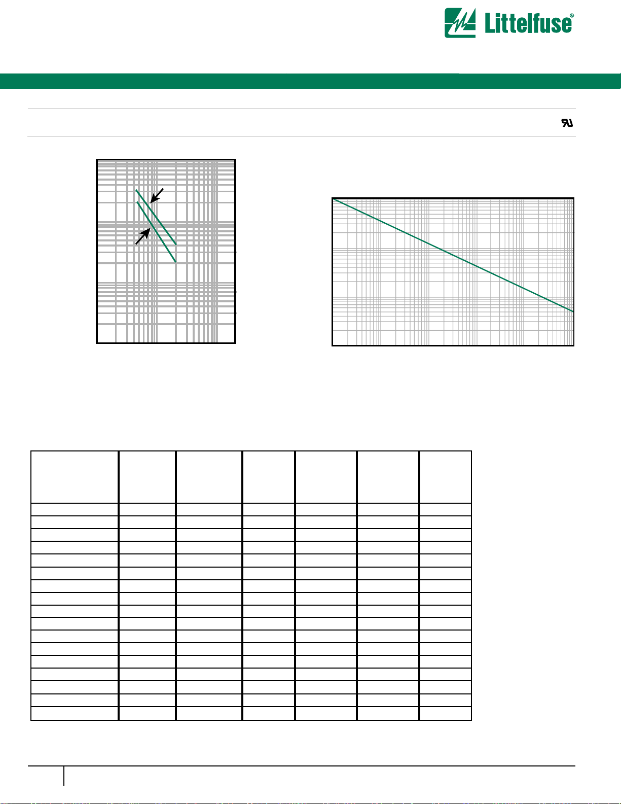
Figure 2 - Peak Pulse Power Rating Curve
ICTE/MPTE Series
1500 Watt Axial Leaded Transient Voltage Suppressors
®
Figure 1 - Typical Junction Capacitance
100,000
Measured at
Zero Bias
10,000
100
Cj (pf)
Measured at
Stand-Off
Voltage (VR)
1000
T
J=2 5°C
f=1.0 MHz
Vsig=50mVp-p
100
1 2 5 10 20 50 100 200
Pulse width (tp)
V(BR) - Breakdown Voltage - Volts
Pp
(kw)
10
1.0
0.1
1µs 1.0µs10µs 100µs 1.0ms 10ms
Pulse Width (tp)
 Loading...