

Page 1
PLED Open LED Protectors
2
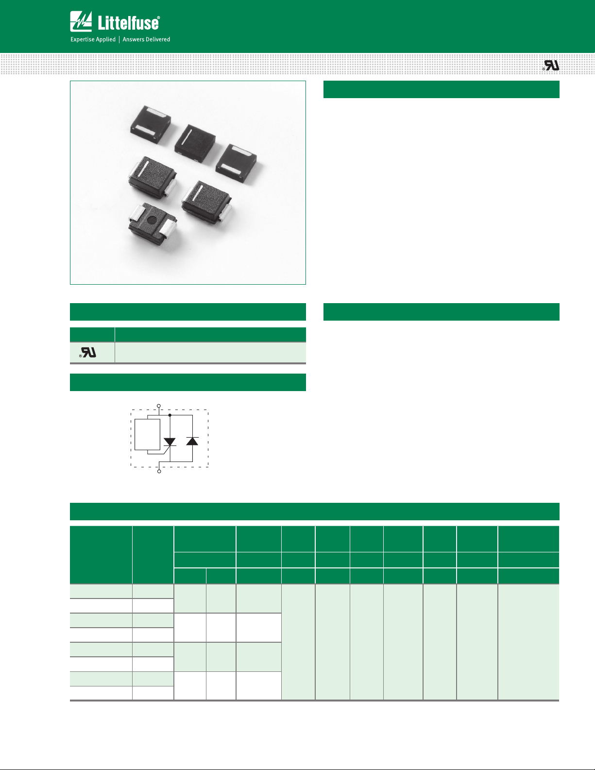
PLED Unidirectional Series
PLED Unidirectional Series (PLEDxUx)
Description
PLED Unidirectional Series (PLEDxUx Series) open LED
protectors provide a switching electronic shunt path around
a single LED that fails as an open circuit. This ensures
the remaining string of LEDs will continue to function
even though a single LED in the string has failed open.
It also provides reverse battery or reverse power polarity
protection.
PLED Unidirectional Series devices were designed to
enable higher reliability in outdoor LED lighting applications
such as street lighting, outdoor signage, aircraft runway
lighting, roadside warning lights and other applications.
Compatible with one, two and three watt LEDs that have
a nominal 3V forward characteristic, PLED Unidirectional
Series devices are available in two surface mount packages,
the DO-214AA and the Quad Flat Pak No-lead (QFN). The
QFN’s low profile, chip scale package (CSP) is ideal for
dense board applications.
Agency Approvals
Agency Agency File Number
E133083
Features & Benefits
• Fast switching
• Reverse Battery/Power
Protection
Schematic Symbol
• Automatically resets after
power cycle
MT
• Available in low prole,
small footprint QFN
Control
Circuit
and Standard DO214AA
packages
• Compatible with industrial
MT1
Cathode
(bar marking side)
lighting environments
Electrical Characteristics (All parameters are measured at T=25°C unless otherwise noted)
Part Number Marking
PLED6UQ12 PL6U
PLED6US PL6U
PLED9UQ12 PL9U
PLED9US PL9U
PLED13UQ12 PL13U
PLED13US PL13U
PLED18UQ12 PL18U
PLED18US PL18U
V
BR
breakdown
Volts Volts mAmps mAmps Amps Volts Amps Volts Volts
Min Max Min Max Max Max Max Max Max Max
6 16 6
9 18 9
13 26 13
18 33 18
V
DRM
breakdown
I
H
30 50 1. 0 1. 2 1. 0 1. 0 250V/µs
I
IT@V
S
T
VT @ IT =
1 Amp
• Compatible with PWM
frequencies up to 10 kHz
• RoHS compliant and
halogen-free
F
VF @ IF =
1 Amp
IF@V
Critical rate of
rise dV/dt
©2013 Littelfuse, Inc.
Specifications are subject to change without notice.
Please refer to www.littelfuse.com for current information.
1
Revision: November 12, 2013
PLED Unidirectional Series
Page 2
PLED Open LED Protectors
QFN 3x3
=)
Q1
C%
PLED Unidirectional Series
Thermal Considerations
Package Symbol Parameter Value Unit
T
DO-214AA
Notes:
1) Standard FR-4 PCB with Copper Pads (Recommended Size)
2) Aluminum PCB
Thickness: 1.6mm
Grade: 1-2 W/mK Thermal Conductivity
Trace thickness: 2 oz
Insulation layer thickness: 215 µm
Solder Pad Dimensions: 2.0mm x 2.8mm (Recommended Size)
3) Aluminum PCB
Thickness: 1.6mm
Grade: 1-2 W/mK Thermal Conductivity
Trace thickness: 2 oz
Insulation layer thickness: 60 µm
Solder Pad Dimensions: 1.27mm x 2.54mm (Recommended Size)
J
T
S
R
θ
JA
Thermal Resistance: Junction to Ambient
Operating Junction Temperature Range -40 to +150 °C
Storage Temperature Range -65 to +150 °C
DO-214AA: 90
DO-214AA: 40
QFN: 120
QFN: 60
1
2
°C/W
1
3
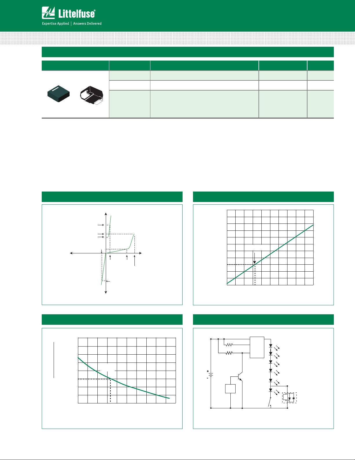
V-I Characteristics
Normalized DC Holding Current vs. Case Temperature LED Interference Test Circuit
H
i
fo oitaR
VBR vs. Junction Temperature
+I
14
12
I
T
I
S
I
H
V
-V
F
+V
V
V
DRM
T
V
BR
I
T
-I
2.0
1.8
C˚ 52
1.6
1.4
C
T(
1.2
H
i
1.0
25 ˚C
0.8
0.6
0.4
-40 -20
0 20 40 60 80 100 120 140 160
– egnah
10
8
6
BR
4
2
0
reP fo tnecV
-4
-6
-8
-40 -20
2.0 Ω, 1/4 W
110 kΩ, 1/4 W
+
V
bat
12 Vdc
-
PWM
25 ˚C
0 20 40 60 80 100 120 140 160
Junction Temperature (TJ) – ˚C
LED
Driver
Q2
2N2222
MT2
Control
Circuit
ON/OFF
Switch
MT1
Unidiretional
PLED
Case Temperature (TC) – ˚C
©2013 Littelfuse, Inc.
Specifications are subject to change without notice.
Please refer to www.littelfuse.com for current information.
2
Revision: November 12, 2013
PLED Unidirectional Series
Page 3

PLED Open LED Protectors
PLED Unidirectional Series
6 LEDs in Series 50% Duty Cycle 10kHz
Note: These two graphs show the current magnitude through the LED string with and without the PLED included. There is no noticeable effect on the LED current magnitude when the
PLED is included in the circuit as compared to the LED current magnitude when the PLED is not in the circuit. (The conversion factor for the test measurement in the graphs above is
10mA/mV for the Pearson coil measurement, therefore, the current magnitude in the first figure is 10mA*8.9 = 89mA, while the second figure is 91mA.)
5 LEDs and 1
PLED
in Series 50% Duty Cycle 10kHz
PLED in the Off-State 10kHz PLED device zeners and then turns fully on 10kHz
Channel 1: current through LEDs (318 mA)
Channel 2: voltage across PLED device (4.5 V)
©2013 Littelfuse, Inc.
Specifications are subject to change without notice.
Please refer to www.littelfuse.com for current information.
Channel 1: current through LEDs (346 mA) and PLED device once it is fully turned on 2.5 μsec later
Channel 2: voltage across PLED device (21.3 V before PLED crowbars with 2 V drop)
3
Revision: November 12, 2013
PLED Unidirectional Series
Page 4

PLED Open LED Protectors
PLxU
XXXXX
Cathode Bar to
Indicate Diode Direction
DO-214AA
PLxU
XXXXX
QFN
Cathode Bar to
Indicate Diode Direction
PLED
x
TYPE
PLED: LED Protector
V
6 Volts
9 Volts
13 Volts
18 Volts
PACKAGE TYPE
Q12: 3.0x3.0mm QFN
S: DO-214AA
DRM
U
Unidirectional
x
PLED Unidirectional Series
Soldering Parameters
Reflow Condition Pb – Free assembly
Pre Heat
- Temperature Min (T
- Temperature Max (T
) 150°C
s(min)
) 200°C
s(max)
- Time (min to max) (ts) 60 – 180 secs
Average ramp up rate (Liquidus Temp
(TL) to peak
T
to TL - Ramp-up Rate 3°C/second max
S(max)
Reflow
- Temperature (TL) (Liquidus) 217°C
- Temperature (tL) 60 – 150 seconds
Peak Temperature (TP) 260
Time within 5°C of actual peak
Temperature (tp)
3°C/second max
+0/-5
°C
30 seconds
Ramp-down Rate 6°C/second max
Time 25°C to peak Temperature (TP) 8 minutes max
Do not exceed 260°C
Physical Specifications
Terminal Material Copper Alloy
Terminal Finish 100% Matte Tin Plated
Body Material
UL recognized epoxy meeting flammability
classification 94V-0
Environmental Specifications
High Temperature
Voltage Blocking
Temperature Cycling
Biased Temperature &
Humidity
High Temperature
Storage
Low Temperature
Storage
Thermal Shock
Resistance to
Solder Heat
MIL-STD-750: Method 1040, Condition A
80% min V
504 hours
MIL-STD-750: Method 1051
-65°C to 150°C, 15-minute dwell,
100 cycles
EIA/JEDEC: JESD22-A101
52VDC, 85°C, 85%RH, 1008 hours
MIL-STD-750: Method 1031
150°C, 1008 hours
-65°C, 1008 hours
MIL-STD-750: Method 1056
0°C to 100°C, 5-minute dwell,
10-second transfer, 10 cycles
MIL-STD-750: Method 2031
260°C, 10 seconds
(VAC-peak), 150°C,
DRM
Part Numbering System
©2013 Littelfuse, Inc.
Specifications are subject to change without notice.
Please refer to www.littelfuse.com for current information.
Part Marking System
4
Revision: November 12, 2013
PLED Unidirectional Series
Page 5

2.54mm
0.100”
1.50mm
0.059”
1.27mm
0.050”
Recommended solder pad layout
(Reference Only)
H
K1
N2
N1
END VIEW
SIDE VIEW
M2 M2
M1
M1
K2
F
E
C
J
B
A
TOP VIEW
BOTTOM VIEW
Packaging
Package Description Packaging Quantity Industry Standard
Q12
S
Dimensions - QFN (3x3) Package
PLED Open LED Protectors
PLED Unidirectional Series
QFN 3x3 5000 EIA-481-1
DO-214AA 2500 EIA-481-1
Dimensions - DO-214 AA Package
Dimensions
Inches Millimeters
Min Typ Max Min Ty p Max
A 0.114 0.118 0.122 2.900 3.000 3.100
B 0.114 0.118 0.122 2.900 3.000 3.100
C 0.075 0.079 0.083 1.900 2.000 2.100
E 0.011 0.015 0.019 0.285 0.385 0.485
F 0.076 0.080 0.084 1.930 2.030 2.130
H 0.035 0.039 0.043 0.900 1.000 1. 10 0
J 0.000 0.004 0.008 0.000 0.100 0.200
K1 0.004 0.008 0.012 0.100 0.200 0.300
K2 0.004 0.008 0.012 0.100 0.200 0.300
M1 0.056 0.060 0.064 1.143 1.530 1.630
M2 0.038 0.042 0.046 0.970 1.070 1.170
N1 0.096 0.100 0.104 2.440 2.540 2.640
N2 0.082 0.086 0.090 2.080 2.180 2.280
B
D
E
Recommended solder pad layout
©2013 Littelfuse, Inc.
Specifications are subject to change without notice.
Please refer to www.littelfuse.com for current information.
0.079"
(2.0mm)
(Reference Only)
(2.0mm)
0.110"
(2.8mm)
0.079"
CASE TEMPERATURE
MEASURING POINT
C
HGK
Dimensions
A
A 0.130 0.156 3.30 3.95
B 0.201 0.220 5.10 5.60
Inches Millimeters
Min Max Min Max
C 0.077 0.087 1.95 2.20
D 0.159 0.181 4.05 4.60
F
E 0.030 0.063 0.75 1.60
F 0.075 0.096 1.90 2.45
G 0.002 0.008 0.05 0.20
H 0.077 0.104 1.95 2.65
K 0.006 0.016 0.15 0.41
5
Revision: November 12, 2013
PLED Unidirectional Series
Page 6

PLED Open LED Protectors
A
B
D
C
W1
N
Reel Dimension
K
0
P
0
P
1
W
D
0
A
1
D
1
P
2
E
2
F
W
0
CARRIER TAPE
COVER TAPE
T
E
1
B
0
Tape Dimension Items
TRAILER
160mm MIN
LEADER
400mm MI N
START
END
CARRIER TAPE
COVER TAPE
Leader and Trailer Dimension of the Ttape
CATHODE BAR
ON THIS SIDE
PLED Unidirectional Series
Tape and Reel Specification - QFN (3x3)
Symbols Description
Inches Millimeters
Minimum Maximum Minimum Maximum
A Reel Diameter N/A 12.992 N/A 330.0
B Drive Spoke Width 0.059 N/A 1.50 N/A
C Arbor Hole Diameter 0.504 0.531 12.80 13.50
D Drive Spoke Diameter 0.795 N/A 20.20 N/A
N Hub Diameter 1.969 N/A 50.00 N/A
W1 Reel Inner Width at Hub 0.488 0.567 12.40 14.40
A0 Pocket Width at bottom 0.126 0.134 3.20 3.40
B0 Pocket Length at bottom 0.126 0.134 3.20 3.40
D0 Feed Hole Diameter 0.059 0.063 1.50 1.60
D1 Pocket Hole Diameter 0.059 N/A 1.50 N/A
E1 Feed hole Position 1 0.065 0.073 1.65 1.85
E2 Feed hole Position 2 0.400 0.408 10.15 10.35
F Feed hole center-Pocket hole 0.215 0.219 5.45 5.55
K0 Pocket Depth 0.039 0.051 1. 00 1.30
P0 Feed hole Pitch 0.153 0.161 3.90 4.10
P1 Component Spacing 0.311 0.319 7.90 8.10
P2 Feed hole center-Pocket hole 0.077 0.081 1.90 2.06
T Carrier Tape Thickness 0. 010 0.014 0.25 0.35
W Embossed Carrier Tape Width 0.453 0.484 11.50 12.30
W0 Cover Tape Width 0.358 0.366 9.10 9.30
DO-214AA Embossed Carrier Reel Pack (RP)
Meets all EIA-481-1 Standards
0.157
(4.0)
©2013 Littelfuse, Inc.
Specifications are subject to change without notice.
Please refer to www.littelfuse.com for current information.
0.472
(12.0)
0.36
(9.2)
0.512 (13.0) Arbor
Hole Dia.
0.49
(12.4)
0.315
(8.0)
Cathode bar on this side
12.99
(330.0)
6
Revision: November 12, 2013
0.059
DIA
(1.5)
Direction of Feed
Dimensions
are in inches
(and millimeters).
Cover tape
PLED Unidirectional Series
 Loading...