

Page 1
Protection Relays & Controls
Feeder Protection–Standard
FPU-32 SERIES (PGR-7200)
Feeder Protection Unit
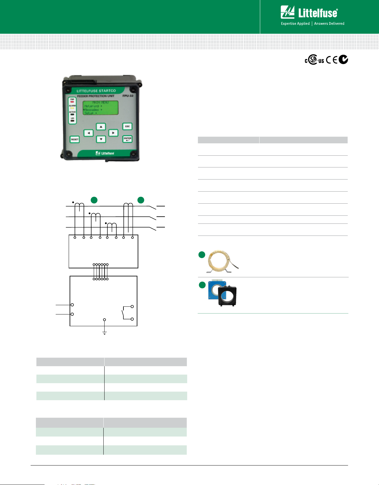
NOTE: The FPU-32 consists of the Feeder Protection Unit (pictured above) and
the MPU-CIM Current Input Module (not pictured).
Simplified Circuit Diagram
PHASE CT
A B
PHASE CT
PHASE CT
GF
CT
Description
The FPU-32 Feeder Protection Unit provides integrated
protection, metering, and data-logging functions. It is an excellent
choice for retrofitting and upgrading older relays because of its
compact size and ability to use existing CTs. The FPU-32 is
used to protect distribution feeders in processing, manufacturing,
petroleum, chemical, and wastewater treatment facilities.
Features & Benefits
FEATURES BENEFITS
IEC & IEEE overcurrent
protection curves
Two setpoint groups
Reduced overcurrent
mode
Data logging
Overload Thermal protection for connected load
Phase loss/Phase reverse
(current)
Unbalance (current) Prevents overheating due to unbalanced phases
Communications
Definite and inverse time set tings for system
coordination; prevents catastrophic failures
Create distinctive set tings for maintenance or for
two different loads
Maintenance mode setting to reduce the risk of
arc-flash hazards
On-board 100-event recorder and remote data
logging helps with system diagnostics
Detects unhealthy supply conditions
Remotely view measured values, event records
& reset trips
MPU-CIM
(Current Input Module)
FPU-32
L1
L2
(Feeder Protection Unit)
Ordering Information
ORDERING NUMBER COMMUNICATIONS
FPU-32-00-00 TIA-232
FPU-32-01-00 TIA-232 & RS-485
FPU-32-02-00 TIA-232 & DeviceNet™
FPU-32-04-00 TIA-232 & Ethernet
NOTE: One of the following is required: MPU-CIM-00-00 Current Input Module, or
MPU-CTI-RT-00 Current Input Module with ring-tonque terminals.
ACCESSORIES REQUIREMENT
Phase CTs Recommended
Ground-Fault CT Optional
MPU-16A-Y92A-96N Optional
Accessories
A
B
Phase Current Transformers
Phase CTs are required to detect phase
currents.
Ground-Fault Transformer
Zero-sequence current transformer detects
ground-fault current. Available with 5-A and 30-A
primary ratings for low-level pickup.
Specifications
Protective Functions
(IEEE Device Numbers)
Input Voltage 65-265 Vac, 30 VA; 80-275 Vdc, 25 W
Power-Up Time 800 ms at 120 vac
Ride-Through Time 100 ms minimum
24-Vdc Source 400 mA maximum
AC Measurements True RMS and DF T, Peak 32 samples/cycle and
positive and negative sequence of fundamental
Frequency 50, 60 Hz
Output Contacts Three Form C
Approvals CSA certified, CE, C-Tick (
Communications TIA-232 (standard); TIA- 485, DeviceNet™, Ethernet (optional)
Analog Output 4-20 mA, programmable
Conformally Coated Standard feature
Warranty 10 years
Mounting
(Control Unit) Panel (standard)
Surface (with MPU-32-SMK converter kit)
(Current Input Module) DIN, Surface
Overload (49, 51)
Phase sequence (4 6)
Unbalance (46)
Phase loss (46)
Definite-time overcurrent (50, 51)
Inverse-time overcurrent (50, 51)
Ground fault (50G/N, 51G/N)
RTD/PTC temperature (49)
Australian)
© 2013 Littelfuse Protection Relays & Controls
Littelfuse.com/fpu-32
Rev: 4-A-050213
Based on Manual Rev 1
 Loading...