

Littelfuse PGR-6200 Users Manual
POWR-GARD®
Motor Protection
PGR-6200 SERIES
Motor Protection Relay
PGR-6200 MANUAL
MOTOR PROTECTION RELAY
June 1, 2009
Revision 2
Publication: PGR-6200-M
Document: P95-P301-00000
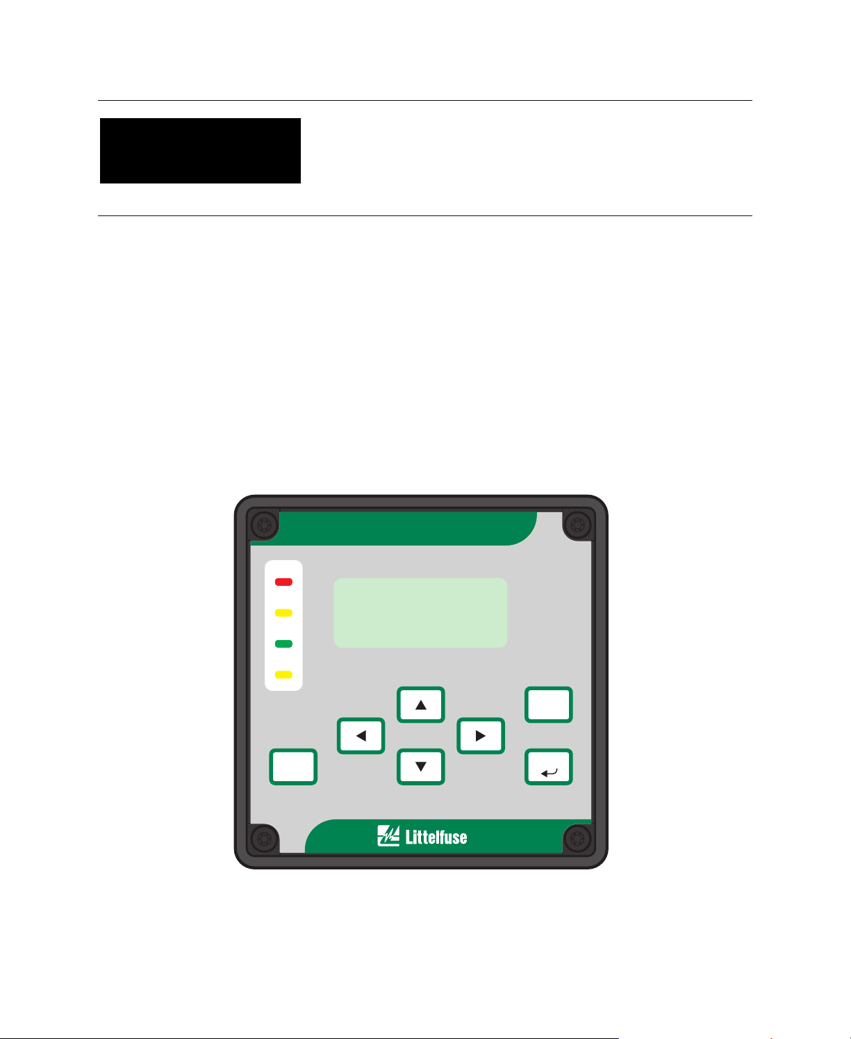
POWR-GARD
MOTOR PROTECTION RELAY PGR-6200
TRIP
ALARM
RUN
UPI
RESET
²Messages Ñ
Copyright © 2009 by Littelfuse, Inc.
MAIN MENU
Metering Ñ
Setup Ñ
All rights reserved.
PGR-6200
SERIES
SERIES
ESC
ENTER

Factory default password is 1111
New Password
See Section 4.5
Motor Identification

Page i
TABLE OF CONTENTS
Page
Table of Contents............................................................i
List of Figures.................................................................ii
List of Tables..................................................................ii
1. INTRODUCTION......................................1-1
1.1 General ............................................................1-1
1.2 PGR-6200 Features........................................1-1
1.2.1 Protection ..............................................1-1
1.2.2 Metering.................................................1-1
1.2.3 Data Logging.........................................1-1
1.2.4 Inputs and Outputs................................1-1
1.2.5 Operator Interface.................................1-1
1.2.6 PGA-0120 Temperature Input Module
(Optional).....................................................1-1
1.2.7 PGA-0140 Differential Current
Module (Optional)........................................1-1
1.2.8 Communications...................................1-1
1.3 Ordering Information .......................................1-1
2. INSTALLATION........................................2-1
2.1 General ............................................................2-1
2.2 PGR-6200 Motor Protection Relay.................2-1
2.3 PGA-0CIM Current Input Module...................2-1
2.4 Sensitive Earth-Fault CT’s ..............................2-1
2.5 PGA-0120 Temperature Input Module...........2-1
2.6 PGA-0140 Differential Current Module ..........2-1
3. SYSTEM WIRING.....................................3-1
3.1 General ............................................................3-1
3.2 Wiring Connections.........................................3-2
3.2.1 PGR-6200 Connections .......................3-2
3.2.1.1 Supply Voltage........................3-2
3.2.1.2 CIM Input.................................3-2
3.2.1.3 Digital Input..............................3-2
3.2.1.4 Analog Output .........................3-2
3.2.1.5 PTC or RTD Input (Local).......3-2
3.2.1.6 I/O Module Interface ...............3-2
3.2.1.7 RS/EIA/TIA-232
Communications..................3-3
3.2.2 PGA-0CIM Connections.......................3-3
3.2.2.1 Standard..................................3-4
3.2.2.2 Residual Earth-Fault............... 3-4
3.2.2.3 Two-CT....................................3-4
3.2.3 PGA-0120 Connections and Address
Selection.............................................3-6
3.2.4 PGA-0140 Connections........................3-6
3.2.4.1 Core Balance...........................3-6
3.2.4.2 PGR-6200 Summation ...........3-6
3.2.4.3 DIF Summation....................... 3-6
3.2.5 Cable Restraint..................................3-6
3.2.6 Dielectric-Strength Testing ...................3-6
4. OPERATION AND SETUP........................4-1
4.1 Display and Indication.....................................4-1
4.1.1 Front-Panel LED Indication ..................4-1
4.1.2 Rear-Panel LED Indication...................4-2
4.1.3 Display Contrast and Test....................4-2
PGR-6200 Motor Protection Relay Rev. 2
Page
4.2 Setup ............................................................... 4-2
4.2.1 Phase-CT Inputs...................................4-2
4.2.2 Earth-Fault-CT Input............................. 4-2
4.2.3 Motor Data ............................................ 4-2
4.2.4 Output Relay Assignment .................... 4-3
4.2.5 Digital Input ........................................... 4-3
4.2.6 Analog Output....................................... 4-4
4.2.7 Miscellaneous Configuration................ 4-4
4.2.8 Communications................................... 4-4
4.3 Metering........................................................... 4-5
4.4 Messages........................................................4-5
4.4.1 Trip Reset.............................................. 4-5
4.4.2 Data Logging......................................... 4-5
4.4.3 Statistical Data......................................4-6
4.4.4 Emergency Thermal Reset ..................4-6
4.5 Password Entry and Programming................ 4-6
4.6 PGA-0120........................................................4-7
4.7 PGA-0140........................................................4-7
5. PROTECTIVE FUNCTIONS.............. 5-1
5.1 General ....................................................... 5-1
5.2 Overload...................................................... 5-1
5.2.1 Thermal Model .................................. 5-1
5.2.2 Locked-Rotor Times.......................... 5-4
5.2.3 Emergency Thermal Reset............... 5-4
5.3 Overcurrent.................................................5-4
5.4 Auxiliary Overcurrent................................... 5-5
5.5 Reduced Overcurrent.................................. 5-5
5.6 Jam ............................................................. 5-5
5.7 Earth Fault...................................................5-5
5.8 Current Unbalance...................................... 5-6
5.9 Phase Loss ................................................. 5-6
5.10 Phase Reverse............................................ 5-6
5.11 Undercurrent............................................... 5-6
5.12 Differential Current Protection..................... 5-6
5.13 Starts per Hour/Time Between Starts......... 5-7
5.14 PTC Temperature (Local)........................... 5-7
5.15 RTD Temperature (Local)........................... 5-7
5.16 RTD Temperature (PGA-0120 Module)...... 5-8
5.17 Hot-Motor Compensation............................ 5-8
6. THEORY OF OPERATION................ 6-1
6.1 Signal-Processing Algorithms..................... 6-1
6.2 Temperature Input Module (PGA-0120) ..... 6-1
6.3 Differential Current Module (PGA-0140)..... 6-1
7. COMMUNICATIONS............................ 7-1
7.1 Personal-Computer Interface......................7-1
7.1.1 Firmware Upgrade............................. 7-1
7.1.2 PGW-COMM..................................... 7-1
7.2 Network Interface........................................ 7-1
7.2.1 TIA-485 Option.................................. 7-1
7.2.2 DeviceNet Option.............................. 7-1
7.2.3 Ethernet Option................................. 7-1

Page ii
Page
8. TECHNICAL SPECIFICATIONS......8-1
8.1 PGR-6200....................................................8-1
8.2 Current Input Module (PGR-0CIM)..............8-3
8.3 Temperature Input Module (PGA-0120)......8-3
8.4 Differential Current Module (PGA-0140).....8-4
Appendix A PGR-6200 Menu Map.......................A-1
Appendix B PGR-6200 Setup Record..................B-1
Appendix C Not Used..........................................C-1
Appendix D PGR-6200 TIA-232 Modbus
Protocol ................................................................D-1
Appendix E Communications Database Table.....E-1
Appendix F Register Formats...............................F-1
Appendix G Ground-Fault Performance Test......G-1
LIST OF FIGURES
Page
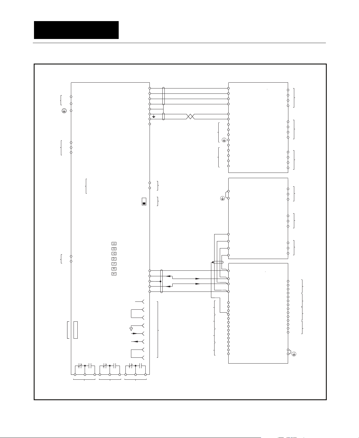
1.1 Motor Protection Relay Block Diagram..........1-2
1.2 PGR-6200 Ordering Information ....................1-3
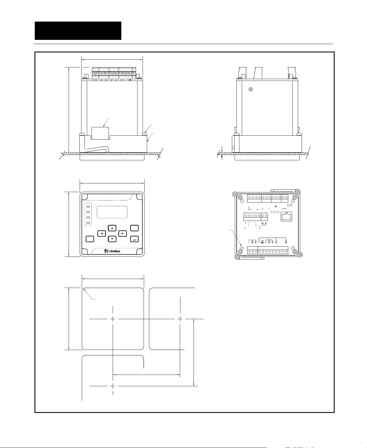
2.1 PGR-6200 Outline and Pane l-Mounting
Details...............................................................2-2
2.2 PGR-6200 Outline and Surface-Mounting
Details...............................................................2-3
2.3 PGA-0CIM Outline and Mounting Details......2-4
2.4 PGC-3082 Outline and Mounting Details.......2-5
2.5 PGC-3140 Outline and Mounting Details.......2-6
2.6 PGC-3026 Outline and Mounting Details.......2-7
2.7 PGA-0120 Outline and Mounting Details.......2-8
2.8 PGA-0140 Outline and Mounting Details.......2-9
3.1 Typical PGR-6200 Connection Diagram........3-1
3.2 Analog-Output Connections............................3-2
3.3 Local Temperature-Sensor Connections.......3-2
3.4 I/O Module Connection Diagram....................3-2
3.5 PGA-0CIM Schematic.....................................3-3
3.6 PGA-0CIM Standard Connections .................3-4
3.7 Other PGA-0CIM Connections.......................3-5
3.8 PGA-0120 Connection Diagram.....................3-7
3.9 Core-Balance Connection...............................3-7
3.10 PGR-6200-Summation Connection................3-8
3.11 PGA-0140-Summation Connections..............3-8
4.1 Menu Example.................................................4-1
4.2 Menu Symbols.................................................4-1
5.1 Class-20 Overload Curve................................5-3
5.2 Asymmetrical-Current Multipliers....................5-5
5.3 Used I
2
t Bias Curve.........................................5-8
PGR-6200 Motor Protection Relay Rev. 2
LIST OF TABLES
Page
3.1 PGA-0420 Adapter Pinout.............................. 3-3
3.2 PGA-0120 Address Selection......................... 3-6
4.1 UPI LED Functions.......................................... 4-1
4.2 Output-Relay Functions.................................. 4-3
4.3 Digital-Input Functions .................................... 4-3
4.4 Analog-Output Parameters............................. 4-4
4.5 Metering Display.............................................. 4-5
5.1 Fault Duration Required for Trip or Alarm...... 5-4
DISCLAIMER
Specifications are subject to change without
notice. Littelfuse, Inc. is not liable for contingent or
consequential damages, or for expenses sustained
as a result of incorrect application, incorrect
adjustment, or a malfunction.
This product has a variety of applications. Those
responsible for its application must take the
necessary steps to assure that each installation
meets all performance and safety requirements
including any applicable laws, regulations, codes,
and standards.
Information provided by Littelfuse is for purposes of
example only. Littelfuse does not assume
responsibility for liability for use based upon the
examples shown.

Page 1-1
PGR-6200 Motor Protection Relay Rev. 2
1. INTRODUCTION
Thermal capacity used during starts
Start time
1.1 General
The POWR-GARD® PGR-6200 is a motorprotection relay that provides integrated protection,
metering, and data-logging functions for fixed- and
variable-frequency applications. The PGR-6200 can
be programmed using the front-panel operator
interface, the TIA-232 port, or an optional
communications network.
The PGR-6200 uses a PGA-0CIM current-input
module for current-transformer connections as
shown in Fig. 1.1. Each PGR-6200 includes a
PGA-0CIM.
1.2 PGR-6200 Features
1.2.1 Protection
• Overload (49, 51)
• Overcurrent (50, 51)
• Earth fault (50G/N, 51G/N)
• Unbalance (46)
• Phase loss (46)
• Phase reverse (46)
• Jam
• Undercurrent (37)
• Starts per hour (66)
• Differential (87)
• PTC overtemperature (49)
• RTD temperature (38, 49)
1.2.2 Metering
• Line currents
• Current unbalance
• Positive-sequence current (I
• Negative-sequence current (I
• Zero-sequence current (3I
)
1
)
2
, calculated)
0
• Earth-leakage current (CT input)
• Differential currents
• Used thermal capacity
• Thermal trend
• RTD temperatures
• Frequency
1.2.3 Data Logging
• One-hundred records
Date and time of event
Event type
Cause of trip
Line currents
Current unbalance
Earth-leakage current
Differential currents
RTD temperatures
• Trip counters
• Running hours
1.2.4 Inputs and Outputs
• Phase-current inputs
• Earth-leakage-current input
• Programmable digital input (24 Vdc)
• 24-Vdc source for digital input
• 4–20-mA analog output, programmable
• Temperature-sensor input, Pt100 RTD or PTC
• I/O module interface
• Three output relays, programmable
• TIA-232 communications
• Network communications
1.2.5 Operator Interface
• 4 x 20 backlit LCD display
• Display-control and programming keys
• LED status indication
1.2.6 PGA-0120 Temperature Input Module (Optional)
• Eight-RTD inputs per module
• Individually selectable RTD types
• Solid-state multiplexing
• Up to three modules per system
• Remote operation up to 1.2 km (4,000’)
• Powered by PGR-6200
1.2.7 PGA-0140 Differential Current Module (Optional)
• 3-CT core balance connection
• 6-CT summation connection
• Remote operation up to 1.2 km (4,000’)
• Powered by PGR-6200
1.2.8 Communications
The standard communications interface is a
TIA-232 port using the Modbus
addition to the standard interface, network
communications options include TIA-485 with both
Modbus
DeviceNet
®
RTU and A-B® DF1 protocols,
TM
, and an IEEE 802.3 port with Modbus®
TCP Ethernet protocol.
®
RTU protocol. In
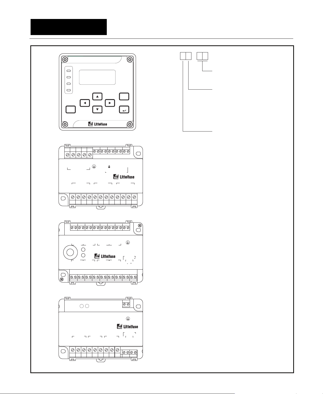
1.3 Ordering Information
See Fig. 1.2 for PGR-6200, PGA-0CIM,
PGA-0120 and PGA-0140 model numbers.
Used thermal capacity
Page 1-2
PGR-6200 Motor Protection Relay Rev. 2
A
SUPPLY
PTC/RTD
INPUT
24VDC
DIGITAL
INPUT
OPTIONAL
NETWORK COM
PGR-6200
2
L1
L2
3
8
TA
17
18
TB
19
TC
MOTOR
PROTECTION
RELAY
LED INDICATORS:
TRIP
13
B
14
C
15
COM
16
29
EF
22
21
20
NC
CONFIGURATION
SELECTION
EARTH FAULT CT
ALARM
RUN
UPI (USER PROG INDICATOR)
NS (NETWORK STATUS)
ON
MS (MODULE STATUS)
REAR
PANEL
ER (ERROR)
L
S
23 AB
24 AA
4-20mA
ANALOG
OUTPUT
ANALOG OUTPUT
SELF/LOOP
POWER SELECTOR
DISPLAY:
4 x 20ALPHANUMERIC LCD,
LED BACKLIGHTING
KEYPAD:
UP
DOWN
LEFT
25
-
+
RIGHT
26
RESET
ESC
ENTER
0V
27
-
28
29
+
30
+24V
31
I/O COMMUNICATIONS
1
DCE
DCD
DTR
SG
RD
TD
CTS
RTS
2
3
4
TIA-232
5
6
7
8
RTD 4
RTD 3
RTD 2
RTD 1
EF1
SPG
+24V
+24V
SHIELD
SHIELD
13
PGA-0CIM
14
CURRENT
15
16
17
18
19
Y
20
21
X
22
E
23
S
24
25
5
26
27
1
MODULE
PGA-0140
15
DIFFERENTIAL
14
13
-
11
+
12
0V
10
0V
15
+
16
-
17
18
14
C
13
D
12
R
11
10
C
9
D
8
R
7
C
6
D
5
R
4
C
3
2
D
R
1
MODULE
LED INDICATORS:
PGA-0120
TEMPERATURE
MODULE
LED INDICATORS:
ADDRESS SWITCHES
INPUT
PWR
COMM
INPUT
PWR
COMM
12 1
11 5
10 S
9R
81
75
6S
5R
4
3
2RS
1
9
8
7
6
5
4
3
2
1
21
22
23
24
25
26
27
28
29
30
31
32
33
34
20
19
PHASE CT
PHASE CT
1
5
PHASE CT
R
1
DIFFERENTIAL
5
CT
C
1
DIFFERENTIAL
5
CT
C
1
DIFFERENTIAL
5
CT
C
R
D
C
SHIELD
R
D
C
R
D
C
SHIELD
R
D
C
SPG
RTD 5
RTD 6
RTD 7
RTD 8
12 9 7
11 1 6
10 4 5
OUTPUT
RELAY 2
OUTPUT
RELAY 3
OUTPUT RELAY CONTACTS SHOWN
OUTPUT
RELAY 1
FIGURE 1.1 Motor Protection Relay Block Diagram.
DE-ENERGIZED.WITH PGR-6200
Page 1-3
PGR-6200 Motor Protection Relay Rev. 2
POWR-GARD
MOTOR PROTECTION RELAY PGR-6200
TRIP
ALARM
RUN
UPI
RESET
27 26 25 24 23 22 21 20 19 18 17 16 15 14 13
1R5SE XYE
EARTH FAULT
POWR-GARD
CURRENT INPUT MODULE
RS51RS51RS51
123456789101112
MAIN MENU
Metering Ñ
²Messages Ñ
Setup Ñ
PHASE A PHASE B PHASE C
PGA-0CIM
PGR-6200
SERIES
SERIES
C
E
O
F
F
M
2
1
PGR-6200/PGR-7200
ESC
ENTER
CBA
PGR-6200-
PGA-0CIM
-
Options:
00 CIM Input
Network Communications:
0 None, TIA-232 only
1 TIA-485 c/w A-B DF1 &
Modbus RTU Protocols
®
2 DeviceNet
®
TM
4 IEEE 802.3 (Ethernet)
Power Supply:
0 Universal ac/dc
(65 to 265 Vac and
80 to 275 Vdc)
NOTE:
The PGR-6200 consists of the
Motor Protection Relay and the PGA-0CIM
Current Input Module. To order the relay only,
add (-MPU) to the part number listed above.
31
34 33 32 30 29 28 27 26 25 24 23 22 21 20 19
CDR CDRCDR CDRS
S
H
INP 8 INP 7 INP 6 INP 5
INP 1 INP 2 INP 3 INP 4
RDC RDCRDC RDC
1234567891011121314
PWR
POWR-GARD®
DIFFERENTIAL INPUT MODULE PGA-0140PGA-0140
PHASE A PHASE B PHASE C
C51C51C51
123456789
POWR-GARD
PWR
TEMPERATURE INPUT MODULE PGA-0120PGA-0120
COMM
S
H
COMM
S
H
P
G
PGR-6200
PGR-6300
S
H
COMM
0
V
15 16 17 18
15 14
S
P
G
PGR-6200
PGR-6300
COMM
0
-
+
V
10 11 12 13
FIGURE 1.2 PGR-6200 Ordering Information.
PGA-0120
2
4
V
PGA-0140
®
+
2
4
V
Supplied Interconnect Cable:
P75-P300-20030 . . PGA-0CIM to PGR-6200 Interconnect Cable,
3124A ..........I/OModule to PGR-6200 Interconnect Cable,
6 m (19’) Included with PGA-0CIM
4 m (13’) Included with PGA-0120 and PGA-0140

Page 1-4
PGR-6200 Motor Protection Relay Rev. 2
Current Transformers:
PGC-3026 ..................Sensitive Earth-Fault CT,
5-A-primary rating,
26-mm (1”) window
PGC-3082 ..................Sensitive Earth-Fault CT,
5-A-primary rating,
82-mm (3.2”) window
PGC-31FC .................Flux Conditioner for
PGC-3082,
70-mm (2.7”) window
PGC-3140…..………..Sensitive Earth-Fault CT
with Flux Conditioner,
5-primary rating,
139-mm (5.5”) window
Other Earth-Fault CT’sContact factory
Phase CT’s.................Contact factory
Accessories:
PGK-0SMK….............Surface-mounting
hardware kit
PGA-016A..................Watertight faceplate cover
PGA-0420 ..................DB9 to RJ-45 Adaptor with
1.5 m (5’) cable
PGA-0440 ..................USB to TIA-232 serial
converter
Software:
PGW-COMM..............PC Interface
PGW-FLSH................Firmware Upgrade
(1)
(1)
(1)
Available at www.littelfuse.com/protectionrelays

Page 2-1
2. INSTALLATION
2.1 General
A basic system consists of a PGR-6200, a
PGR-0CIM, and three 1-A- or 5-A-secondary linecurrent transformers. Earth-fault protection can be
provided from a core-balance CT or from phase
CT’s. A core-balance CT (1-A, 5-A, or PGC-3000
series) is recommended. In addition to a single
PTC/RTD input provided on the PGR-6200, up to
three PGA-0120 modules (eight RTD inputs per
module) and one PGA-0140 differential module can
be connected to a PGR-6200.
The PGR-6200 switch-mode power supply is rated
65 to 265 Vac and 80 to 275 Vdc.
All modules can be mounted in any orientation.
PGR-6200 Motor Protection Relay Rev. 2
2.5 PGA-0120 Temperature Input Module
Outline and mounting details for the PGA-0120
are shown in Fig. 2.7. The PGA-0120 will fit inside
most motor RTD-termination junction boxes and it is
certified for use in Class I, Zone 2 hazardous
locations. The PGA-0120 can be surface or DIN-rail
mounted.
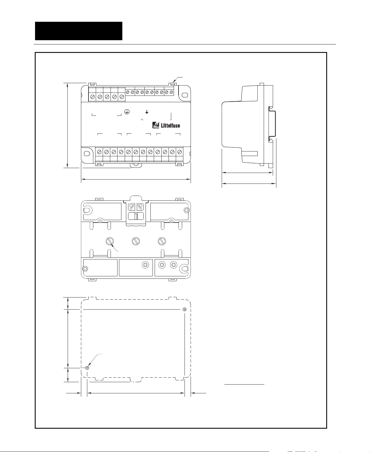
2.6 PGA-0140 Differential Current Module
Outline and mounting details for the PGA-0140
are shown in Fig 2.8. The PGA-0140 can be surface
or DIN-rail mounted.
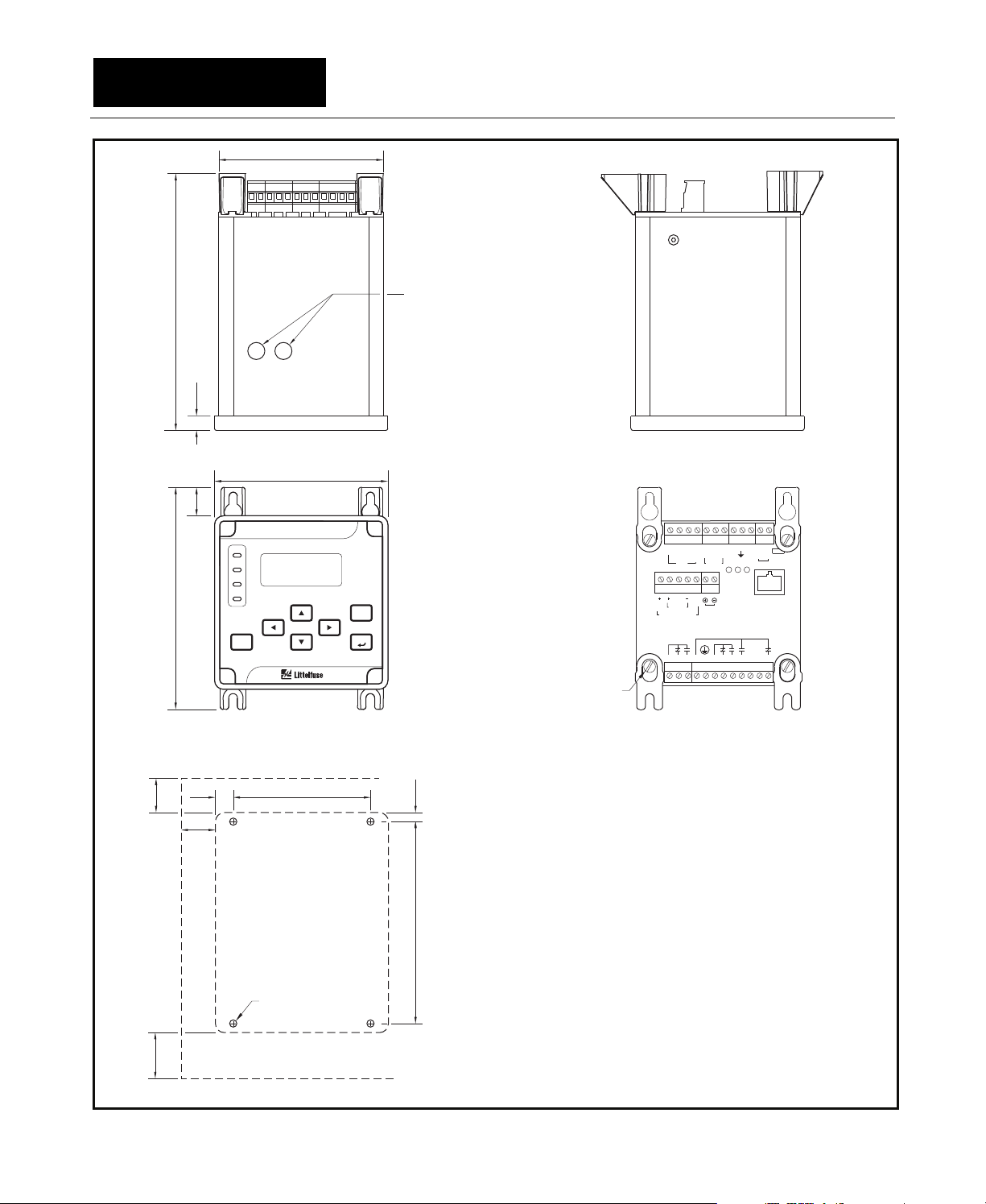
2.2 PGR-6200 Motor Protection Relay
Outline and details for PGR-6200 panel-mounting
are shown in Fig. 2.1. The PGR-6200 mounts in a
92 mm (3.62”) ¼ DIN square cutout and is secured
by a panel-mount clamp. Insert the PGR-6200
through the panel cutout and slip the panel-mount
clamp over the PGR-6200 body. Slide the clamp
forward until the latch tabs snap into the mating
holes. Lock the unit in place by tightening the four
clamp screws against the panel.
Caution:
Do not over tighten the clamp screws as this may
deform the clamp and release the latch tabs.
Outline and details for PGR-6200 surfacemounting are shown in Fig. 2.2. Ensure that the L/S
switch is set before installing surface-mounting
brackets. See Section 3.2.1.4 for switch positions.
A detailed installation instruction sheet is included
with the PGK-0SMK, Surface-Mounting Hardware
Kit.
2.3 PGA-0CIM Current Input Module
The PGA-0CIM can be surface or DIN-rail
mounted. Outline and mounting details are shown
in Fig. 2.3. To minimize CT-lead burden, a
PGA-0CIM can be located close to the CT’s. The
PGA-0CIM terminates phase- and earth-fault-CT
secondaries⎯shorting blocks are not required for
PGA-0CIM outputs.
2.4 Sensitive Earth-Fault CT’s
Outline and mounting details for the PGC-3026,
PGC-3082, and PGC-3140 are shown in Figs. 2.4,
2.5, and 2.6.
Page 2-2
PGR-6200 Motor Protection Relay Rev. 2
91.1
(3.59)
(5.20)
132.0
LATCH TAB
CLAMP SCREWS
PANEL-MOUNT CLAMP
1.6 (0.06) TO 4.8 (0.19)
PANEL THICKNESS
96.0
92.0
(3.78)
(3.62)
TOP
96.0
(3.78)
POWR-GARD
MOTOR PROTECTION RELAY PGR-6200
TRIP
ALARM
RUN
UPI
RESET
MAIN MENU
Metering Ñ
²Messages Ñ
Setup Ñ
FRONT
92.0
(3.62)
R=4.8 (0.19)
MAXIMUM
PGR-6200
SERIES
SERIES
ESC
ENTER
6-32 CABLING RESTRAINT
FASTENING POINT
4 PLACES
NOTES:
1.2.DIMENSIONS IN MILLIMETRES (INCHES).
REAR VIEW SHOWN WITHOUT NETWORK
COMMUNICATIONS.
SIDE
20 2321
18 19
13 15 1714 16
TATBT
AB C
C
C
O
M
CIM
TEMP AN OUT
ERMSN
31 29 2730 28
26 25
SH0
2
V
4
COMM
DIG IN
V
I/O MODULE
RELAY 2
RELAY 1
12 11 10 9 8 7 6 5 4 3 2 1
REAR
22
EFABA
S
TIA-232 ONLY
RELAY 3
L
2
L
/
N
1
24
A
LS
100.0
100.0
(3.94)
MINIMUM
PANEL CUTOUT DETAIL
FIGURE 2.1 PGR-6200 Outline and Panel-Mounting Details.
(3.94)
MINIMUM
Page 2-3
PGR-6200 Motor Protection Relay Rev. 2
91.1
(3.59)
HOLE PLUGS
(TOP AND BOTTOM
142.9
(5.63)
8.0
(0.32)
SURFACES)
19.0
122.5
(0.75)
16.6
(4.82)
(0.39)
19.0
(0.75)
(0.65)
POWR-GARD
MOTOR PROTECTION RELAY PGR-6200
TRIP
ALARM
²Messages Ñ
RUN
UPI
RESET
(NOTE 5)
M4 OR 8-32 TAP
TOP
96.0
(3.78)
MAIN MENU
Metering Ñ
Setup Ñ
FRONT
76.29.9
(3.00)
PGR-6200
SERIES
SERIES
ESC
ENTER
5.0
112.0
(0.20)
(4.41)
SIDE
20 2321
24
22
18 19
13 15 1714 16
TATBT
AB C
C
O
M
CIM
31 29 2730 28
SH0
2
V
4
COMM
V
I/O MODULE
RELAY 2
12 11 10 9 8 7 6 5 4 3 2 1
EFABA
C
TEMP AN OUT
ERMSN
S
26 25
DIG IN
RELAY 1
TIA-232 ONLY
RELAY 3
L
2
/
N
A
LS
L
1
NOTE 3
REAR
NOTES:
1.
DIMENSIONS IN MILLIMETRES (INCHES).
2.
REAR VIEW SHOWN WITHOUT NETWORK
COMMUNICATIONS.
3.
MOUNT SURFACE MOUNTING BRACKETS
WITH 6-32 x 0.375 PAN-HEAD SCREWS AND
LOCKWASHERS. (INCLUDED WITH
SURFACE-MOUNTING KIT).
4.
PGR-6200 MOUNTING SCREWS: M4 OR
8-32 PAN HEAD.
5.
MINIMUM CLEARANCE TO ADJACENT
OBJECTS.
25.4
(1.00)
(NOTE 5)
MOUNTING DETAIL
FIGURE 2.2 PGR-6200 Outline and Surface-Mounting Details.
Page 2-4
PGR-6200 Motor Protection Relay Rev. 2
CABLE-TIE EYELET
4 PLACES
87.0
(3.43)
27 26 25 24 23 22 21 20 19 18 17 16 15 14 13
1R5SE XYE
EARTH FAULT
POWR-GARD
CURRENT INPUT MODULE
PHASE A PHASE B PHASE C
RS51RS51RS5 1
1
3456789 101112
2
PGA-0CIMPGA-0CIM
112.5
(4.43)
F
1
CBA
C
E
O
F
M
2
PGR-6200/PGR-7200
TOP
SHORTING SCREWS
A,B,&C(NOTES4&5)
52.5
(2.07)
56.0
(2.20)
SIDE
(NOTE 3)
BOTTOM
12.5
(0.50)
60.0
(2.36)
M4 OR 8-32 TAP
14.5
(0.57)
100.06.8 6.8
(3.94)(0.27) (0.27)
MOUNTING DETAIL
FIGURE 2.3 PGA-0CIM Outline and Mounting Details.
NOTES:
DIMENSIONS IN MILLIMETRES (INCHES).
1.
MOUNTING SCREWS: M4 OR 8-32.
2.
OVERALL HEIGHT WHEN MOUNTED
3.
ON DIN EN50022 35-mm x 7.5-mm
TOP-HATRAIL.
SHORTING SCREWS ARE ACCESSIBLE
4.
FROM BOTTOM OF PGA-0CIM.
5.
SHORTING SCREWS: 6-32 x 0.375
NICKEL-PLATED-BRASSBINDING HEAD.
DO NOT SUBSTITUTE.
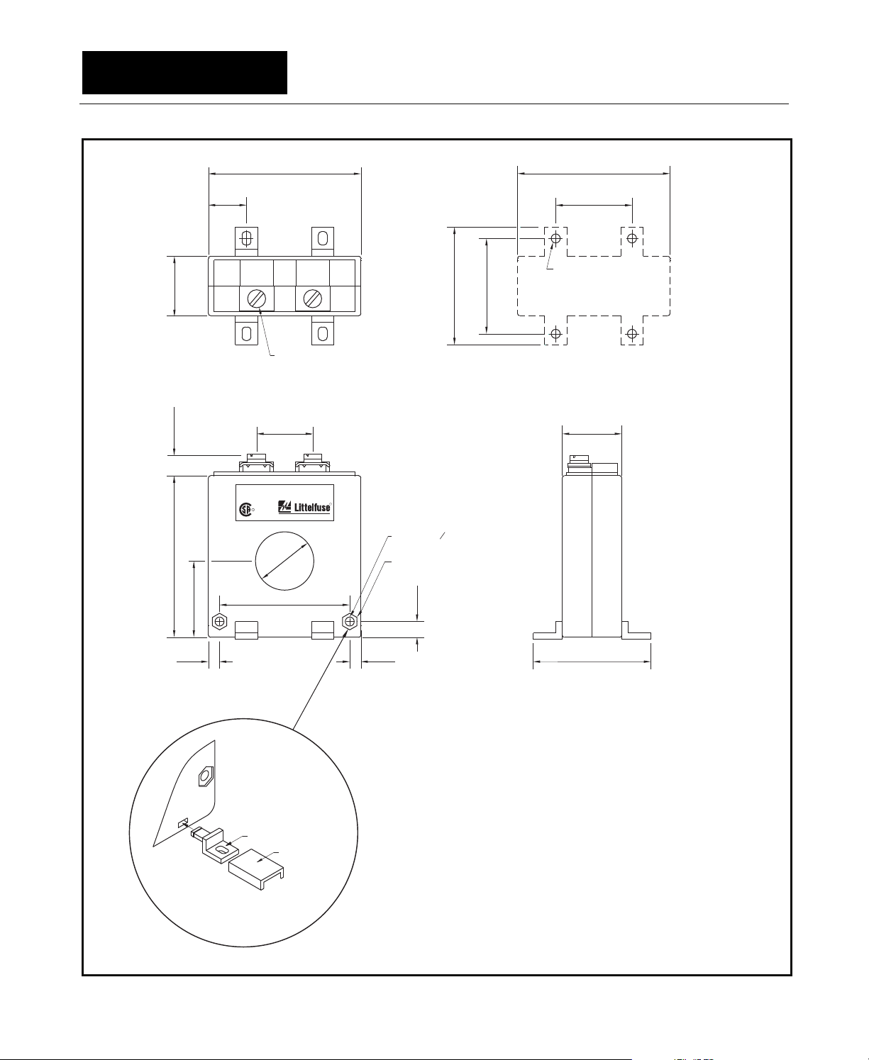
Page 2-5
PGR-6200 Motor Protection Relay Rev. 2
26.5
110.0 MAX
72.0
(1.04)
(0.43)
(2.83)
17.0
(0.67)
68.0
(2.68)
P
2
SS
2
1
P
1
M5 SCREWS
52.5
(2.07)
42.6
(1.68)
68.0
(2.68)
34.0
(1.34)
M4 OR 8-32 TAP
TOP MOUNTING DETAIL
26.525.0
(1.04)(0.98)
PGC-3026
EARTH FAULTCURRENT
LR 53428
TRANSFORMER
TM
POWR-GARD Products
26.0
(1.02)
R
4.0 (0.16) 0
RECESSED FOR
7-mm HEX NUT
3.0 (0.12) DEEP
600 VClass,
Insulation ClassA
R
USC
34.0
(1.34)
58.0
(2.28)
7.0
FRONT SIDE
MOUNTING FOOT
INSTALLATION
TOOL
DETAIL ‘A’
FIGURE 2.4 PGC-3026 Outline and Mounting Details.
(0.87)
52.55.05.0
(2.07)(0.20)(0.20)
NOTES:
1.
DIMENSIONS IN MILLIMETRES (INCHES).
2.
PRESS MOUNTING FEET IN PLACE USING
INSTALLATION TOOL PROVIDED (DETAIL ‘A’)
3.
MOUNTING SCREWS: M4 OR 8-32.
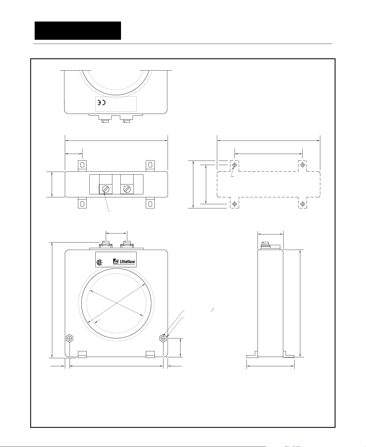
Page 2-6
PGR-6200 Motor Protection Relay Rev. 2
1
P
2
S
1
S
30.0
(1.18)
(5.43)
138.0 MAX
20.5
(0.81)
121.0
(4.76)
121.0
(4.76)
80.0
(3.15)
NOTE 2
56.0
46.0
(2.21)
(1.81)
M5 SCREWS
TOP MOUNTING DETAIL
25.0
(0.98)
PGC-3082
EARTH FAULTCURRENT
600 VClass,
Insulation ClassA
R
LR 53428
USC
PGC-31FC
FLUX
CONDITIONER
(OPTIONAL)
TRANSFORMER
TM
POWR-GARD Products
82.0
(3.23)
69.8
(2.75)
R
5.0 (0.20) 0
RECESSED FOR
8-mm HEX NUT
1.0 (0.04) DEEP
30.0
(1.18)
(4.96)
126.0
110.05.5 5.5
(4.33)(0.22) (0.22)
FRONT SIDE
NOTES:
1.
DIMENSIONS IN MILLIMETRES (INCHES).
2.
MOUNTING SCREWS: M4 OR 8-32.
3.
PRESS MOUNTING FEET IN PLACE USING
INSTALLATION TOOL PROVIDED.
FIGURE 2.5 PGC-3082 Outline and Mounting Details.
22.0
(0.87)
56.0
(2.21)

Page 2-7
PGR-6200 Motor Protection Relay Rev. 2
POWR-GARD Products
USC
TM
LR53428
TRANSFORMER
215.0
(8.46)
R
InsulationClass A
600V Class,
PGC-3140 EARTH FAULT CURRENT
215.0
(8.46)
26.5
(1.04)
162.0
(6.38)
R
64.0
(2.52)
236 MAX
31.0
(9.29)
(1.22)
P
2
SS
2
1
P
1
52.3
(2.06)
M5 OR 10-32 TAP
M5 SCREWS
TOP MOUNTING DETAIL
25.0
(0.98)
1
S
1
P
139.7
(5.50)
FLUX CONDITIONER
(INCLUDED)
BONDING
SCREW
5.0 (0.20) DIA
31.0
(1.22)
215.0
(8.46)
198.0 8.58.5
(7.80) (0.33)(0.33)
NOTES:
1. DIMENSIONS IN MILLIMETRES (INCHES).
2.
MOUNTING SCREWS: M5 OR 10-32.
FIGURE 2.6 PGC-3140 Outline and Mounting Details.
60.0
(2.36)
SIDEFRONT

Page 2-8
PGR-6200 Motor Protection Relay Rev. 2
CABLE-TIE EYELET
4 LOCATIONS
31
34 33 32 30 29 28 27 26 25 24 23 22 21 20 19
CDR CDRCDR CDRS
87.0
(3.43)
S
H
INP 8 INP 7 INP 6 INP 5
INP 1 INP 2 INP 3 INP 4
RDC RDCRDC RDC
1234567891011121314
ADDRESS SWITCH
ACCESS COVER
POWR-GARD
PWR
TEMPERATURE INPUT MODULE PGA-0120PGA-0120
COMM
S
H
112.5
(4.43)
H
S
H
TOP
S
P
G
PGR-6200
PGR-6300
COMM
0
V
15 16 17 18
2
4
V
52.5
(2.07)
(NOTE 3)
56.0
(2.20)
SIDE
12.5
(0.50)
60.0
(2.36)
M4 OR 8-32 TAP
14.5
(0.57)
100.06.3 6.3
(3.94)(0.25) (0.25)
MOUNTING DETAIL
FIGURE 2.7 PGA-0120 Outline and Mounting Details.
NOTES:
DIMENSIONS IN MILLIMETRES (INCHES).
1.
MOUNTING SCREWS: M4 OR 8-32.
2.
OVERALL HEIGHT WHEN MOUNTED
3.
ON DIN EN50022 35-mm x 7.5-mm
TOP-HAT RAIL.

Page 2-9
PGR-6200 Motor Protection Relay Rev. 2
CABLE-TIE EYELET
4 PLACES
87.0
(3.43)
PWR
POWR-GARD®
DIFFERENTIAL INPUT MODULE PGA-0140PGA-0140
PHASE A PHASE B PHASE C
C51C51C51
123456789
COMM
112.5
(4.43)
TOP
15 14
S
P
G
PGR-6200
PGR-6300
COMM
0
-
+
V
10 11 12 13
®
+
2
4
V
52.5
(2.07)
(NOTE 3)
56.0
(2.20)
SIDE
BOTTOM
12.5
(0.50)
60.0
(2.36)
M4 OR 8-32 TAP
14.5
(0.57)
100.06.8 6.8
(3.94)(0.27) (0.27)
MOUNTING DETAIL
FIGURE 2.8 PGA-0140 Outline and Mounting Details.
NOTES:
DIMENSIONS IN MILLIMETRES (INCHES).
1.
MOUNTING SCREWS: M4 OR 8-32.
2.
OVERALL HEIGHT WHEN MOUNTED
3.
ON DIN EN50022 35-mm x 7.5-mm
TOP-HATRAIL.

Page 2-10
PGR-6200 Motor Protection Relay Rev. 2
This page intentionally left blank.
Page 3-1
PGR-6200 Motor Protection Relay Rev. 2
3. SYSTEM WIRING
3.1 General
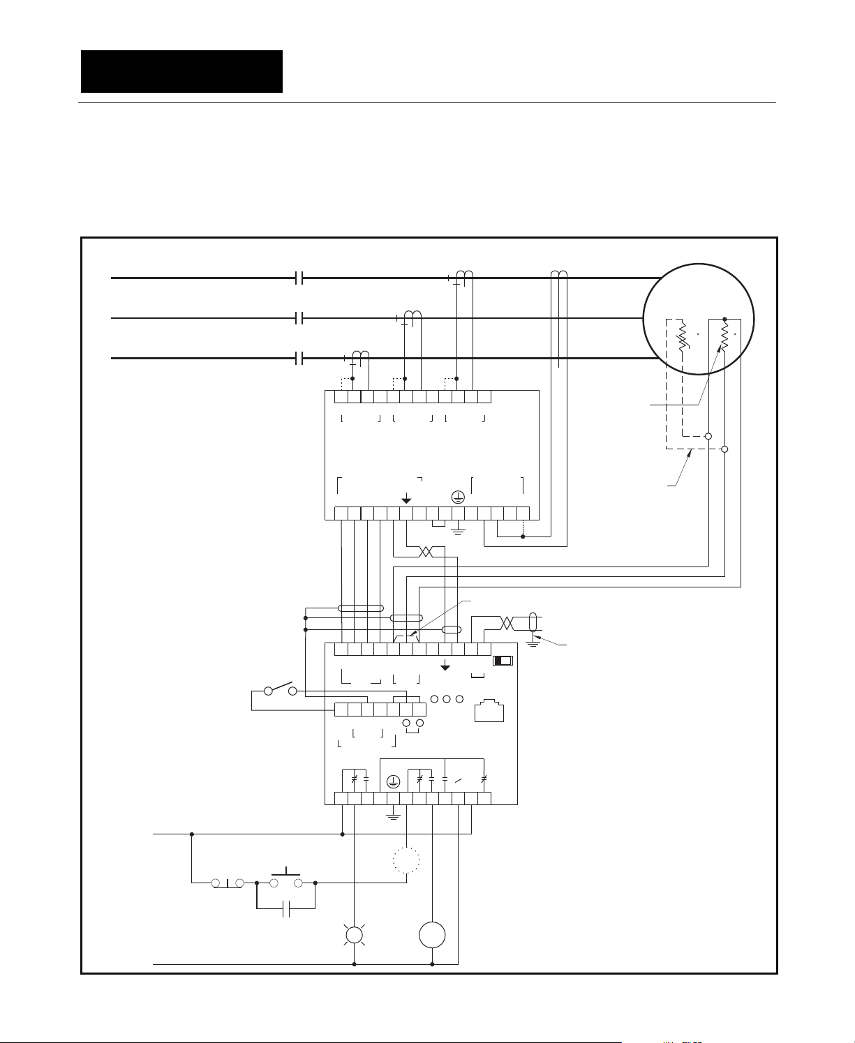
A typical connection diagram for a PGR-6200 and
PGA-0CIM is shown in Fig. 3.1. See Sections 3.2.3
and 3.2.4 for PGA-0120 and PGA-0140
connections.
CONTACTOR
A
K1
B
PHASE CT'S
(NOTE 9)
EARTH-FAULT CT
MOTOR
(NOTE 6)
C
11 10 9
12
111555
PHASE C PHASE B PHASE A
8
7654321
RRR
SSS
PGA-0CIM
(NOTE 8)
PGR-6200/PGR-7200
C
E
O
F
M
WHITE
RED
GREEN
BCC
O
M
CIM
SH-++
COMM
2
17
BLUE
TEMP
0
V
18 19
BROWN
TBTAT
+
DIG IN
(NOTE 7)
S1
ABC
13 14 15 16
BLACK
(NOTE 3)
133114301529162817271826192520 21 22 23 24
A
24
V
I/O MODULE
RELAY 2 RELAY 1
12 11 10 9 8 7 6 5 4 3 2 1
L1
STOP
START
(NOTE 5)
K1
K1
L2/N
FIGURE 3.1 Typical PGR-6200 Connection Diagram.
E
F
1
YX
20 21 22 23 24 25
EFA
C
AN OUT
TIA-232 ONLY
ERMSN
S
-
PGR-6200
RELAY 3
L
2
N
K1AALARM
EARTH FAULT
ES5R261
(NOTE 10)
(NOTE 6)
A
B
A
LS
18
L
1
+t t
Pt100 RTD
SENSOR
ALTERNATE
CONNECTION FOR
PTC-THERMISTOR
27
SENSOR(S)
OUTPUT
(NOTE 4)
NOTES:
PGR-6200 REAR VIEW SHOWN.
1.
RELAYS SHOWN DE-ENERGIZED.
2.
GROUND CABLE SHIELDS AT PGR-6200 END ONLY.
3.
GROUND OUTPUT-CABLE SHIELD AT RECEIVER
4.
END ONLY.
5.
ALTERNATE CONTACTOR-COIL LOCATION.
6.
ALTERNATE CONNECTION FOR PTC-THERMISTOR
SENSOR(S).
PROGRAMMABLE DIGITAL INPUT .
7.
8.
DOTTED LINES SHOW 1-A-CT CONNECTIONS.
9.
A-B-C PHASE ROTATION REQUIRED.
10.
EARTH-FAULT INPUT IS NOT POLARITY SENSITIVE.
11.
OPTIONAL NETWORK COMMUNICATIONS
NOT SHOWN.
Page 3-2
PGR-6200 Motor Protection Relay Rev. 2
3.2 Wiring Connections
3.2.1 PGR-6200 Connections
The PGR-6200 wire-clamping terminal blocks
accept 24 to 12 AWG (0.2 to 2.5 mm
These terminal blocks unplug to allow the
PGR-6200 to be easily removed.
2
) conductors.
3.2.1.1 Supply Voltage
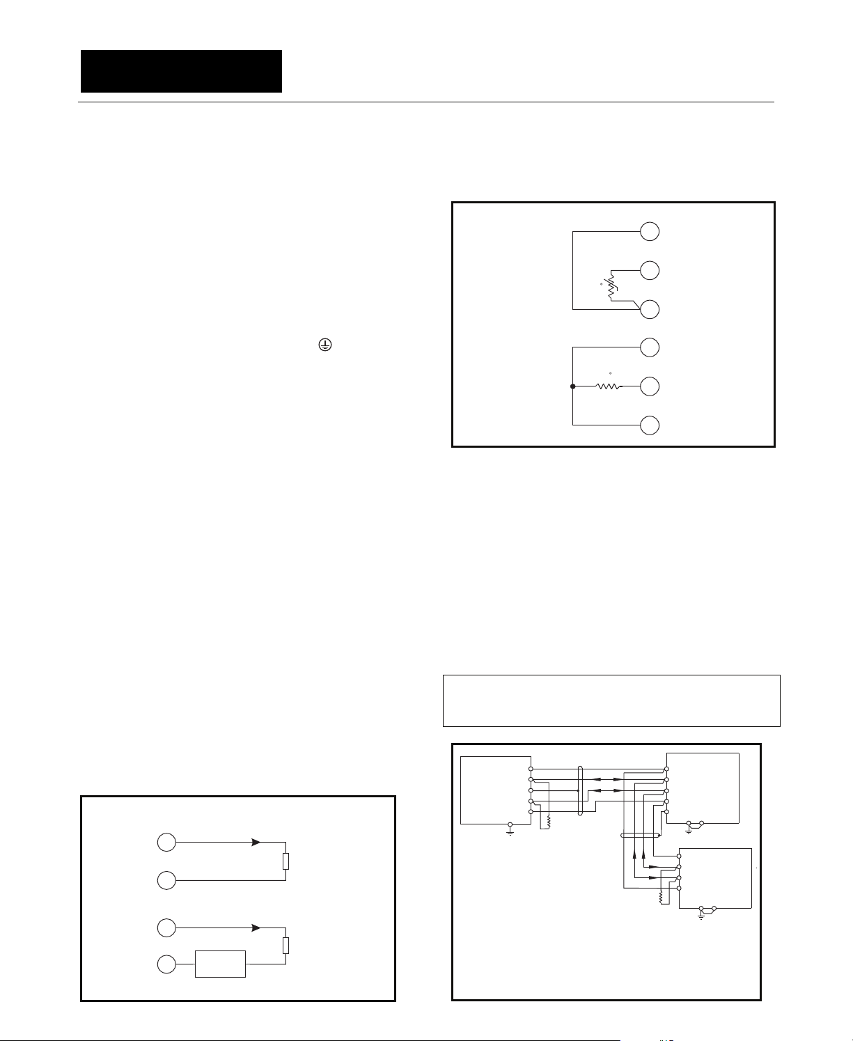
3.2.1.5 PTC or RTD Input (Local)
The temperature-sensor input on the PGR-6200
can be configured for either PTC or Pt100 RTD
operation as shown in Fig. 3.3.
a) PTC
19 TC
Derive supply voltage from the line side of the
motor controller or from an independent source.
Connect supply voltage to terminals 2 and 3 (L1
and L2/N) as shown in Fig. 3.1. In 120-Vac
systems, L2/N is designated as the neutral
conductor. For direct-current power supplies, use
L1 for the positive terminal and L2/N as the
negative terminal. Ground terminal 8 (
).
+t
b) Pt100 RTD
18 TB
17 TA
19 TC
3.2.1.2 CIM Input
Connect the PGR-6200 to the PGA-0CIM as
t
18 TB
shown in Figs. 3.6 and 3.7 using the cable
provided.
3.2.1.3 Digital Input
A 24-Vdc digital input is provided on terminals 25
and 26. This input is polarity sensitive. For a
logical 1, terminal 26 must be positive with respect
to terminal 25. See Section 4.2.5.
The current-limited 24-Vdc source (terminals
27 & 31) can be used to power the digital input.
3.2.1.4 Analog Output
The analog output is switch selectable as self
powered or loop powered.
For the self-powered connection, set the L/S
switch to the S position. The self-powered
connection is shown in Fig. 3.2 (a). The analog
output is referenced to the I/O module supply,
terminal 27.
For the loop-powered connection, set the L/S
switch to the L position. The loop-powered
connection is shown in Fig. 3.2 (b). In looppowered operation, the analog-output is isolated
from all other PGR-6200 terminals.
a) SELF POWERED (S POSITION)
24AA
RECEIVER
23AB
b) LOOP POWERED (L POSITION)
24AA
+-
23AB
LOOP
SUPPLY
FIGURE 3.2 Analog-Output Connections.
TERMINATION
RECEIVER
TERMINATION
FIGURE 3.3 Local Temperature-Sensor Connections.
3.2.1.6 I/O Module Interface
The I/O module interface supplies power and
communications to optional I/O modules such as
the PGA-0120 and PGA-0140.
I/O module communication is based on the twowire multi-drop TIA-485 standard but uses a
proprietary protocol. Overall line length must not
exceed 1.2 km (4,000’). For line lengths exceeding
10 m (33’), 150-Ω terminations are required at the
cable ends. I/O modules are supplied with 4 m
(13’) of interconnection cable. See Fig. 3.4.
Note: I/O communication is shared with the display.
Incorrect wiring can cause the display and keypad to
freeze.
RED
31
GREEN
+
PGR-6200
MOTOR
PROTECTION
NOTES:
1.
2.
FIGURE 3.4 I/O Module Connection Diagram.
30
29
WHITE
-
28
BLACK
27
RELAY
3
INTERCONNECT CABLE BELDEN 3124A
OR EQUIVALENT.
R =150 OHMS, 1/4 WATT. REQUIRED FOR LINE
t
LENGTHS EXCEEDING 10 M (33’).
R
t
17 TA
+
-
R
t
18
PGA-0120
17
16
TEMPERATURE
INPUT
15
MODULE
11
20
19
10
-
11
PGA-0140
+
12
DIFFERENTIAL
13
MODULE
14 15
Page 3-3
PGR-6200 Motor Protection Relay Rev. 2
3.2.1.7 RS/EIA/TIA-232 Communications
An RJ-45 TIA-232 connector is provided on the
rear panel of the PGR-6200. This port uses
Modbus
PGW-COMM PC-interface software. For Modbus
RTU protocol, see Appendix D. The slave ID and
communication baud rate are set in the Setup ⏐
Hardware ⏐ Local Comms menu.
Table 3.1 shows the pinout for the optional
PGA-0420 adapter for operation with PGW-COMM.
See Fig 3.1 for RJ-45 pinout.
For a USB connection, use an PGA-0440 adapter.
®
RTU protocol to communicate with
TABLE 3.1 PGA-0420 Adapter Pinout
SYMBOLIC NAME RJ-45 DB9
RI/DSR 1 9
CD 2 1
DTR 3 4
SG 4 5
RD 5 2
TD 6 3
CTS 7 8
RTS 8 7
®
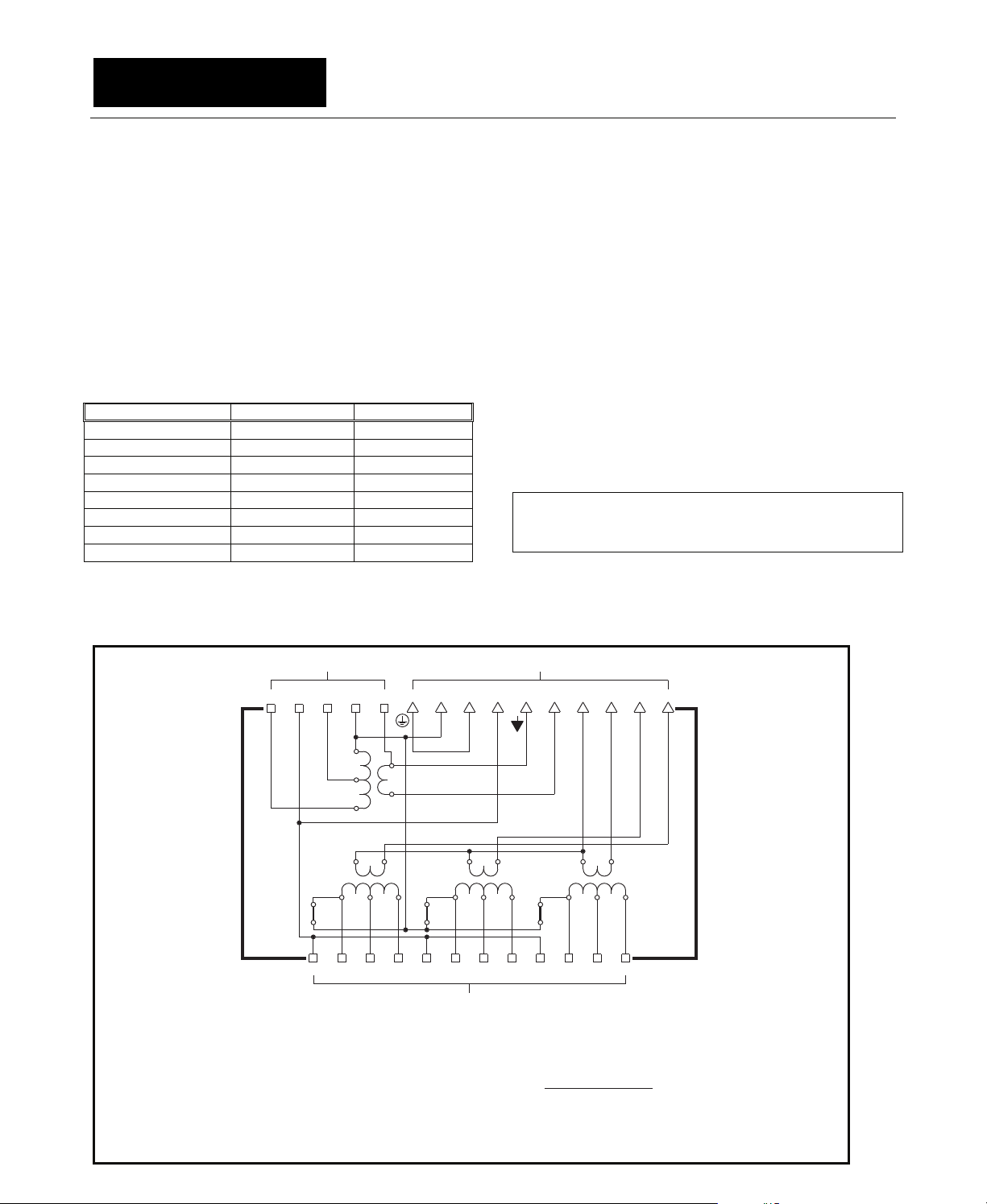
3.2.2 PGA-0CIM Connections
The PGA-0CIM CT-input terminal blocks accept 22
to 10 AWG (0.3 to 4.0 mm
remaining PGA-0CIM clamping blocks accept 24 to
12 AWG (0.2 to 2.5 mm
2
) conductors.
The PGA-0CIM contains four signal-conditioning
interface transformers which are interconnected as
shown in Fig. 3.5. These transformers isolate the
PGR-6200 from the phase and earth-fault CT's. The
PGA-0CIM eliminates the need for CT shorting
contacts when the PGR-6200 is disconnected.
Phase-CT and earth-fault-CT secondaries can be
simultaneously grounded through terminal 22 and a
jumper to terminal 20. For applications where the CT
secondaries must be grounded at another location,
the CT secondaries can be isolated by removing
shorting screws A, B, and C through holes in the
bottom of the PGA-0CIM. See Figs. 2.3 and 3.5.
Note: A-B-C phase sequence and polarity must be
observed when connecting phase CT’s. See Section
4.2.1.
Connect the PGA-0CIM to the PGR-6200 as
2
) conductors. The
shown in Figs. 3.6 and 3.7 using the cable
provided.
TB3
TB2
27126R25524S23E22 21 20
AB
R1S2531
NOTES:
1.
REMOVE SHORTING SCREWS A, B, AND C TO ISOLATE PHASE-CT
AND EARTH-FAULT-CT SECONDARIES FOR IN-LINE APPLICATIONS.
2.
SHORTING SCREWS A, B, AND C: 6-32 x 0.375
NICKEL-PLATED-BRASS BINDING HEAD.
3.
SHORTING SCREWS A, B, AND C MUST NOT BE REMOVED FOR
RESIDUAL OR TWO-CT CONNECTIONS.
4.
EACH TERMINAL ON TB1 AND TB3 WILL ACCEPT ONE
NO. 10 AWG CONDUCTOR
FIGURE 3.5 PGA-0CIM Schematic.
XY19E
RS6571
5
4
TB1
18 17 16 15
F
1
E
F
2
C
R9S105111
8
DO NOT SUBSTITUTE
14 13
C
C
O
M
BA
12
Page 3-4
PGR-6200 Motor Protection Relay Rev. 2
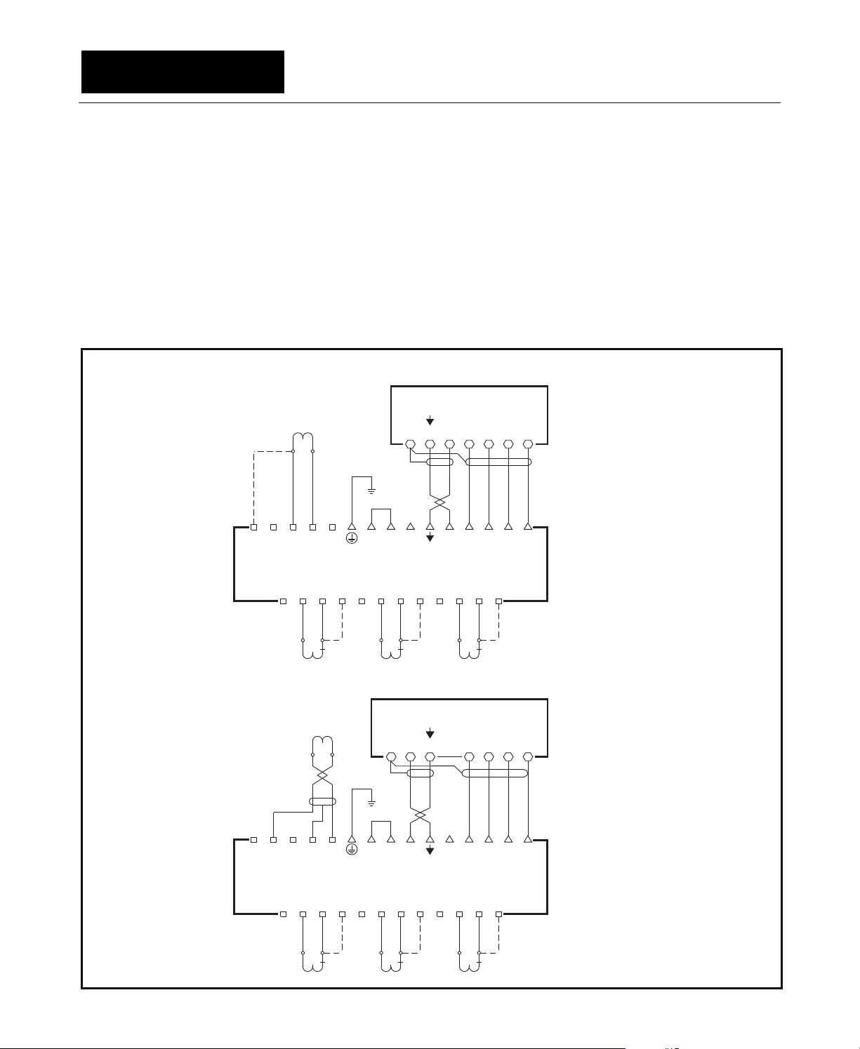
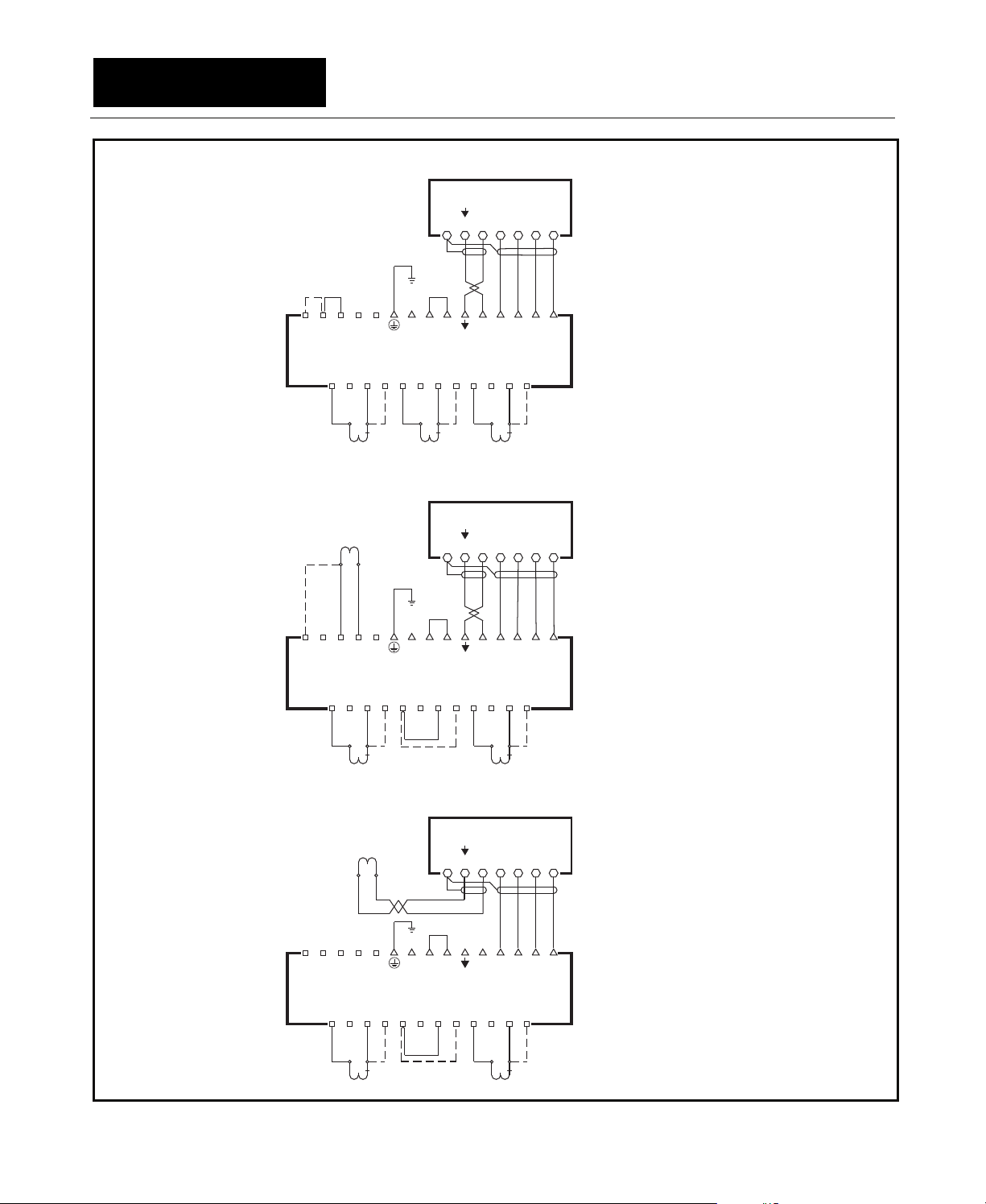
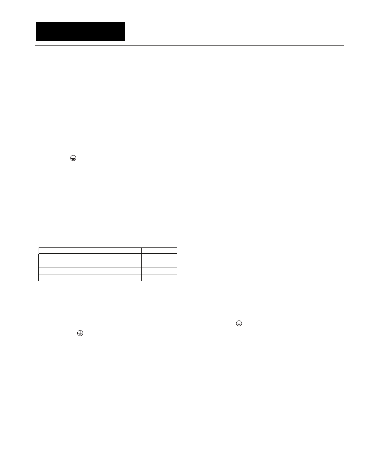
3.2.2.1 Standard
Standard connections with earth-fault CTs are
shown in Fig. 3.6. Dotted lines indicate 1-A-CT
connections. Use shielded cable for PGC-3000series current-transformer connections. Ensure
only current-carrying phase conductors pass
through the earth-fault-CT window and that ground
conductors do not.
3.2.2.2 Residual Earth-Fault
The wired residual earth-fault connection is
shown in Fig. 3.7 (a). Dotted lines indicate 1-A-CT
connections. Use three identical CT's for this
connection.
The PGR-6200 also calculates residual current.
See Section 4.2.2.
3.2.2.3 Two-CT
The two-CT connection is shown in Figs. 3.7 (b)
and 3.7 (c). Dotted lines indicate 1-A-CT
connections. Since this connection derives the
current in the unmonitored phase, it should be used
only in retrofit applications where it is not possible
to install a third CT.
a) STANDARD CONNECTION
1-A OR 5-A
EARTH-FAULT
CT
5A
1A
272726262525242423232222212120
11RR55SSE
XXY
PGA-0CIM
R
S
112233445
A
CT
5
5A
1
1A
R
PGR-6200
19
S
5
5A
CT B
S
H
181817
E
F
1
1
1A
21212229
BROWN
R
C
O
E
M
F
CCBBA
16161515141413
GREEN
RED
BLUE
16
15
E
C
C
F
O
2
M
S
5
5A
CT C
14
1
1A
WHITE
13
B
BLACK
A
S TERMINALS ARE GROUNDED
THROUGH TERMINAL 22
b) STANDARD CONNECTION WITH PGC-3000-SERIES CURRENT TRANSFORMER
PGC-3XXX
PGR-6200
S
E
H
F
2229
BLUE
BROWN
C
O
M
GREEN
RED
WHITE
A
13
BLACK
E
PGA-0CIM
R
S
CT A
R
5
1
566778899101011111212
5A
1A
FIGURE 3.6 PGA-0CIM Standard Connections.
20
S
CT B
19
17
16
15
14
13
Y
E
E
C
C
B
5
5A
F
F
1
1
1A
O
2
M
R
S
5
5A
CT C
1
1A
A
S AND E TERMINALSARE GROUNDED.
S THROUGH TERMINAL22,
E THROUGH TERMINAL18
Page 3-5
PGR-6200 Motor Protection Relay Rev. 2
a) RESIDUAL CONNECTION
27
1A 5A
26
1
25
5
R
PGA-0CIM
R
2
1
PGR-6200
S
H
18
19
20
21
22
23
24
E
S
1
5
S
5
4
3
5A
1A
E
Y
X
F
1
5
S
R
8
7
6
5A
1
1A
21
BROWN
17
R
9
2229
10
E
F
BLUE
E
F
2
16
S
C
O
M
16
GREEN
15
C
O
M
11
5
5A
A
B
C
13
14
15
RED
WHITE
BLACK
13
14
A
B
C
1
12
1A
SHORTING SCREWS
A, B, & C MUST
NOT BE REMOVED.
R TERMINALS ARE
GROUNDED THROUGH
TERMINAL 22.
CT A
CT B CT C
b) TWO-CT CONNECTION
1-A OR 5-A
EARTH-FAULT
1A
25
26
27
R
1
R
1
CT
5A
23
24
E
S
5
PGA-0CIM
5
S
4
3
2
5A
CT A
PGR-6200
S
H
18
19
20
21
22
1
5
1A
E
Y
X
F
1
5
S
R
8
7
6
5A
1
1A
21
BROWN
17
R
9
E
F
2229
BLUE
E
F
2
10
16
S
CT C
C
O
M
16
GREEN
15
C
O
M
5
11
5A
15
RED
C
12
A
B
C
13
14
WHITE
BLACK
13
14
A
B
1
1A
SHORTING SCREWS
A, B, & C MUST
NOT BE REMOVED.
R TERMINALS ARE GROUNDED
THROUGH TERMINAL 22.
EARTH-FAULT CT MUST
NOT BE GROUNDED.
c) TWO-CT CONNECTION WITH PGC-3000-SERIES CURRENT TRANSFORMER
PGR-6200
R
BROWN
BLUE
20
X
S
6
S
H
18
19
E
Y
F
1
5
8
7
5A
PGC-3XXX
21
22
23
24
25
26
27
R
1
E
S
5
PGA-0CIM
1
5
S
R
2
1
5
4
3
5A
1A
C
E
O
F
M
16
2229
21
GREEN
16
17
C
E
O
F
M
2
1
S
R
11
10
9
1A
A
B
C
13
14
15
RED
WHITE
BLACK
13
14
15
A
B
C
1
5
12
5A
1A
SHORTING SCREWS
A, B, & C MUST
NOT BE REMOVED.
R TERMINALS ARE GROUNDED
THROUGH TERMINAL 22.
CT A
FIGURE 3.7 Other PGA-0CIM Connections.
CT C
Page 3-6
PGR-6200 Motor Protection Relay Rev. 2
3.2.3 PGA-0120 Connections and Address Selection
Connect the PGA-0120 Temperature Input
Module to the PGR-6200 using the four-conductor
shielded cable (Belden 3124A or equivalent)
supplied with the PGA-0120 as shown in Fig. 3.8.
The PGR-6200 24-Vdc supply can power up to
three PGA-0120 modules.
Connect RTD’s to the PGA-0120 as shown in
Fig 3.8. When the RTD module is installed in a
motor junction box, RTD-lead shielding is not
required. PGA-0120 terminal blocks accept 24 to
12 AWG (0.2 to 2.5 mm
2
) conductors.
Connect surge-protection (SPG) terminal 20 to
terminal 19 (
) and ground terminal 19.
The PGA-0120 has two switches to select its
network address. See Fig. 3.8. Up to three
PGA-0120 modules can be connected to the I/O
MODULE bus, and each RTD-module address
must be unique. If one module is used, address 1
must be used. If two RTD Modules are used,
addresses 1 and 2 must be used. If three RTD
Modules are used, addresses 1, 2, and 3 must be
used.
Table 3.2 shows the address selection format.
TABLE 3.2 PGA-0120 Address Selection
ADDRESS SWITCH 1 SWITCH 2
0 (Off line) Open Open
1 (First RTD module) Closed Open
2 (Second RTD module) Open Closed
3 (Third RTD module) Closed Closed
3.2.4 PGA-0140 Connections
Connect the PGA-0140 Differential Input Module
to the PGR-6200 using four-conductor shielded
cable (Belden 3124A or equivalent) as shown in
Fig. 3.4.
Connect the surge-protection (SPG) terminal 15
to terminal 14 (
The PGA-0140 CT-input terminal blocks accept
22 to 10 AWG (0.3 to 4.0 mm
remaining PGA-0140 clamping blocks accept 24 to
12 AWG (0.2 to 2.5 mm
), and ground terminal 14.
2
) conductors. The
2
) conductors.
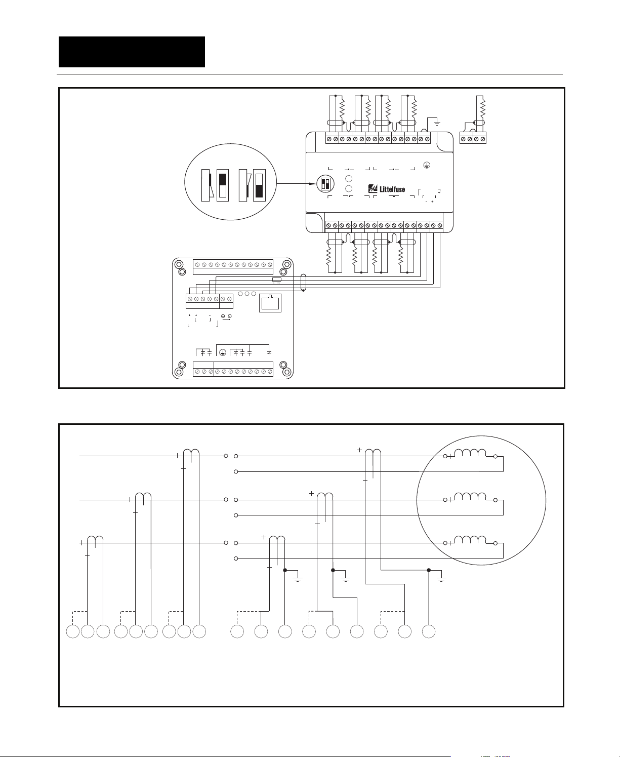
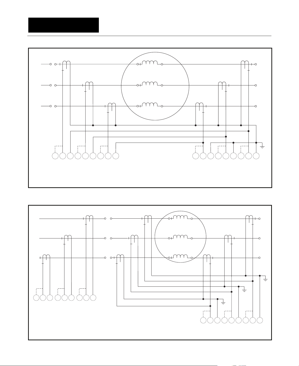
3.2.4.2 PGR-6200 Summation
The PGR-6200-summation connection uses three
phase CT’s and three differential CT’s as shown in
Fig. 3.10. Both CT-ratio and CT-saturation
characteristics must be matched to avoid differential
currents under motor starting and running
conditions. The PGA-0140 module should be
located near the PGA-0CIM to minimize CT-wire
length. It is preferred to use three dedicated phase
CT’s and three core-balance differential CT’s as
described in Section 3.2.4.1.
For the delta connection, the FLA Rating is set
equal to the motor’s full-load current multiplied by
√3.
3.2.4.3 DIF Summation
The DIF-summation connection uses six
differential CT’s as shown in Fig. 3.11. Both CTratio and CT-saturation characteristics must be
matched to avoid differential currents under motor
starting and running conditions. It is preferred to
use three core-balance CT’s as described in
Section 3.2.4.1. This six-CT connection allows the
CT’s and PGA-0140 to be placed near the motor to
minimize power-cable and CT-lead length.
3.2.5 Cable Restraint
All conductors should be restrained within
100 mm (4") of the terminal blocks. Four cablingrestraint points are provided on the PGR-6200 rear
panel. Secure cables to the PGA-0CIM, PGA-0120
and PGA-0140 using the cable-tie eyelets and the
cable ties provided. See Figs. 2.1, 2.3, 2.7 and 2.8.
3.2.6 Dielectric-Strength Testing
Dielectric-strength testing can be performed only
on CT inputs, supply-voltage input, and output
relays. Unplug all other I/O and remove the
PGA-0CIM
dielectric-strength testing.
connection (terminal 22) during
3.2.4.1 Core Balance
The core-balance connection uses three
differential CT’s as shown in Fig. 3.9. To minimize
power-cable and CT secondary lead lengths, both
the differential CT’s and the PGA-0140 can be
located near the motor. The primary rating of the
differential CT does not have to match the phaseCT primary rating and is usually selected with a
lower ratio resulting in more sensitive differential
protection. The core-balance method avoids CTmatching issues and is the preferred connection.
Page 3-7
PGR-6200 Motor Protection Relay Rev. 2
ADDRESS
SELECTION
SWITCHES
12
OPEN
OPEN
CLOSED OPEN
18 19 20 2321
RELAY 1
ERMSN
22
S
TIA-232 ONLY
RELAY 3
L
2
/
N
13 15 1714 16
31 29 2730 28
2
4
V
26 25
SH0
V
COMM
DIG IN
I/O MODULE
RELAY 2
12 11 10 9 8 7 6 5 4 3 2 1
FIGURE 3.8 PGA-0120 Connection Diagram.
S
P
G
PGR-6200
PGR-6300
COMM
0
V
15 16 17 18
WHITE
BLACK
GREEN
ALTERNATE
2-WIRE RTD
CONNECTION
S
H
2
4
V
RED
C
RD
3-WIRE RTD
CONNECTION
t° t° t°t° t°
31
34 33 32 30 29 28 27 26 25 24 23 22 21 20 19
CDR CDRCDR CDRS
S
H
INP 8 INP 7 INP 6 INP 5
12
OPEN
PWR
COMM
INP 1 INP 2 INP 3 INP 4
S
RDC RDCRDC RDC
H
1234567891011121314
H
POWR-GARD
TEMPERATURE INPUT MODULE PGA-0120PGA-0120
S
H
t° t° t°t°
24
LS
INTERCONNECT CABLE
BELDEN 3124A OR EQUIVALENT
L
1
ØA
ØB
ØC
S 15S 15S5
1
10876 43211
12
PGA-0CIM
FIGURE 3.9 Core-Balance Connection.
1
4
MOTOR
2
5
3
6
C15C15C51
765432189
PGA-0140
CONNECTIONS:
WYE: ØA & 1, ØB & 2, ØC & 3,4&5&6
DELTA: ØA&1&6, ØB&2&4,ØC&3&5
Page 3-8
PGR-6200 Motor Protection Relay Rev. 2
1
ØA
2
ØB
3
ØC
S51
234
CONNECTIONS:
WYE: ØA & 1, ØB & 2, ØC & 3,4&5&6
DELTA: ØA&1&6,ØB&2&4,ØC&3&5
S51
678
S51
101112
FIGURE 3.10 PGR-6200-Summation Connection.
MOTOR
C51
789
NOTES:
1. REMOVE MPU-CIM SHORTING SCREWS
A, B, & C.
C51
456
PGA-0140PGA-0CIM
4
5
6
C51
123
1
ØA
2
ØB
3
ØC
S 15S 15S5
10876 43211112
PGA-0CIM
CONNECTIONS:
WYE: ØA& 1, ØB & 2, ØC & 3,4&5&6
DELTA: ØA&1&6,ØB&2&4,ØC&3&5
FIGURE 3.11 DIF-Summation Connectiion.
4
MOTOR
5
6
C51
789
PGA-0140
C51
456
C51
123

Page 4-1
PGR-6200 Motor Protection Relay Rev. 2
4. OPERATION AND SETUP
4.1.1 Front-Panel LED Indication
Menu: Setup | System Config | UPI LED
4.1 Display and Indication
All PGR-6200 information displays and settings
can be accessed using the PGR-6200 menu
system, the TIA-232 interface, or a networkcommunications interface.
In the following sections, menu items and setup
parameters are listed in italics and are shown in the
format displayed on the alphanumeric LCD. The
LCD cannot display subscripts and superscripts.
Menu selection is in the following format:
Menu 1 | Sub Menu 1 | Sub Menu 2 | Sub Menu
3 |……
Example: For the menu item shown in Fig. 4.1,
the notation is Setup | System Ratings | CT Primary
Metering 4
Messages 4
5Setup4 Protection4
•
•
•
•
•
•
FIGURE 4.1 Menu Example.
Fig. 4.2 shows the symbols that assist in
navigating the menu system and how these
symbols relate to the arrow keys on the PGR-6200.
See the PGR-6200 menu map in Appendix A.
vSystem Ratings4
Digital Input4
6CT Primary→
EF Source→
EF-CT-Primary→
The red TRIP and yellow ALARM LED’s indicate
a trip or alarm condition. The green RUN LED is
OFF when current is not detected, flashes when the
motor is starting, and is ON when the motor is
running. The yellow UPI LED is a userprogrammable indicator and its function is defined
by one of the menu selections shown in Table 4.1.
TABLE 4.1 UPI LED Functions
SELECTION DEFINITION
None LED remains off.
Trip1 Trip1 condition exists.
Trip2 Trip2 condition exists.
Trip3 Trip3 condition exists.
Alarm1 Alarm1 condition exists.
Alarm2 Alarm2 condition exists.
Alarm3 Alarm3 condition exists.
Relay1 Relay1 is energized.
Relay2 Relay2 is energized.
Relay3 Relay3 is energized.
Digital Input Digita l Input is valid.
Current Detected Current is above minimum
threshold.
Current > 125% Current is above 125% FLA.
Run Mode PGR-6200 is in Run mode.
ETR PGR-6200 is in Emergency
Thermal Reset state
Start Inhibit In I2t or starts-per-hour inhibit
state.
Network Run1 Run1 is issued by a network
command.
Net Activity Activity is detected on the
communications interface.
Reduced OC Reduced Overcurrent protection
is active.
These symbols indicate the
menu level. Up to five submenulevel symbols may be displayed.
Use left-arrow key or ESC to
move back one menu level.
Cursor indicates selected
menu item and shape
indicates available scrolling
directions.
Indicates top of list. Scroll
using down-arrow key.
Scroll using up- or downarrow keys.
Indicates bottom of list.
Scroll using up-arrow key.
FIGURE 4.2 Menu Symbols.
Indicates that there are related data
displays to the left or right of this
display. Use left- or right-arrow
keys to view adjacent data displays.
¬¬¬¬¬ TITLE ¬Ñ
½ MENU ITEM 1 Ñ
² MENU ITEM 2 ¼
« MENU ITEM 3 *
Use right-arrow key to
select submenu.
Use right-arrow key to
display data.
Indicates active item in
list-type set-point
displays.

Page 4-2
PGR-6200 Motor Protection Relay Rev. 2
4.1.2 Rear-Panel LED Indication
The three LED’s on the rear panel are labeled
ER, MS, and NS. The red ER (Error) LED is OFF
during normal operation and is ON when there is a
processor error or during firmware-update
operation. Output relays are de-energized when
this LED is ON. The MS (Module Status) and NS
(Network Status) LED’s are used for networkcommunications and firmware-update annunciation.
The specific colour and function of these LED’s is
defined by the network-communications option
installed in the PGR-6200. For detailed information,
see the applicable communications manual.
4.1.3 Display Contrast and Test
Contrast control and test operator-interface
features are available when the display is in Local
mode. To prevent a Display Comm Trip, select
Disabled in the Setup ⏐ Hardware ⏐ OPI Display ⏐
Trip Action menu. To enter Local mode, press the
up-arrow, right-arrow, and ENTER keys
simultaneously.
In Local mode, all face-plate LED’s are ON and
the display indicates three menu items; Contrast,
Address, and Enter Test Mode. Use the up- and
down-arrow keys to select the menu item.
Contrast: Use the right- and left-arrow keys to
increase or decrease contrast.
Address: The display address indicates 1 and
cannot be changed.
Enter Test Mode: Press the right-arrow key to
enter test mode. In test mode, the LED test,
Display test, and Display-Heater test are
automatically performed. The Interactive-Key test
is then entered and the following symbols are
displayed when a key is pressed.
Left Key: ¬
Right Key Ñ
Up Key «
Down Key ½
ESC: ^
ENTER: ª
RESET: Press RESET to exit this menu.
Press the ESC key to exit Local mode and return to
the PGR-6200 menu. Re-enable OPI Diplay Trip
Action.
4.2 Setup
Certain PGR-6200 settings cannot be changed
when the motor is running. See Appendix B.
4.2.1 Phase-CT Inputs
Menu: Setup | System Ratings | CT Pri mary
The CT-primary setting range is 1 to 5,000 A. To
maintain specified accuracy, phase CT’s should be
selected with a primary rating between 100 and
300% of motor full-load current.
For A-B-C sequence, the +Seq I
larger than the –Seq I
display value and positive
2
current unbalance is indicated. Negative current
unbalance will be indicated if the phase sequence is
B-A-C. If negative unbalance is indicated, correct the
phase-CT connections. Severe current unbalance
may be indicated when phase-CT polarity is
incorrect.
4.2.2 Earth-Fault-CT Input
Menu: Setup | System Ratings | EF Source
Menu: Setup | System Ratings | EF-CT Primary
The EF Source menu selects the earth-fault
source as Calculated (3I
The Calculated (3I
) or Measured (Ict).
0
) selection uses the 3I0 value
0
obtained from the sequence-component calculation
and is based on the phase currents only. Set the
EF-CT Primary to the phase-CT-primary rating
when Calculated (3I
The Measured (I
) is selected.
0
) selection uses current
ct
measured by an earth-fault CT or the residual
connection. Set EF-CT Primary to the earth-faultCT-primary rating when an earth-fault CT is used.
For the sensitive PGC-3082 and PGC-3140 earthfault CT’s, set EF-CT Primary to 5 A. Set EF-CT
Primary to the phase-CT-primary rating for the
residual-CT connection.
The setting range for the EF-CT-Primary rating is
1 to 5,000 A.
Note: Calculated 3I
does not detect CT saturation.
0
Enable overcurrent protection when earth-fault
current can exceed 15 times the phase-CT primary
rating.
Note: 3I
and Ict values will be shown in the
0
Metering ⏐ Earth Leakage display regardless of the
EF Source selection or CT connections.
Note: For the residual connection and Calculated
(3I0) selection, the earth-fault-trip setting should be
greater than 5%.
4.2.3 Motor Data
Menu: Setup | System Ratings
Menu: Setup | Protection ⏐ Overload
In the System Ratings menu, motor data must be
entered for the FLA Rating (full-load current),
Frequency, and Service Factor.
Set Frequency at 50 Hz , 60 Hz, or Variable. Use
Variable for adjustable-speed drive applications.
LR Current (locked-rotor current), LR Time Cold
(cold locked-rotor time), and LR Time Hot (hot
locked-rotor time) must be entered in the Setup |
Protection ⏐ Overload menu to provide customized
overload protection. See Sectio n 5.2.
display value is
1

Page 4-3
PGR-6200 Motor Protection Relay Rev. 2
4.2.4 Output Relay Assignment
Menu: Setup | Relay Outputs | Relay x
Menu: Setup | Relay Outputs | RY Pulse Time
Each of the three output relays can be assigned
to one of the functions listed in Table 4.2. More
than one relay can be assigned the same function.
Trip and alarm assignments operate in the selected
fail-safe or non-fail-safe mode.
The default assignment for Relay 1 is Trip1, for
Relay 2 is Alarm1, and for Relay 3 is None. The
default mode setting for all three relays is Fail-Safe.
4.2.5 Digital Input
Menu: Setup | Digital Input | Input Function
Menu: Setup | Digital Input | Start Bypass
Menu: Setup | Digital Input | Bypass Del ay
Menu: Setup | Digital Input | Trip Delay
The digital input can be assigned to one of the
functions listed in Table 4.3.
When the digital input is assigned the Trip1
function, Start Bypass, Bypass Delay, and Trip
Delay set points become active. When Start
Bypass is enabled, the digital input is bypassed
during a start for the duration specified by Bypass
Delay. Start detection is based on motor current.
After the Bypass Delay, the digital input is enabled
and a trip occurs if the digital-input voltage is
removed for the time specified by the Trip Delay. If
Start Bypass is disabled, Bypass Delay is not used
enabled. The bypass feature can be used in pumpcontrol applications to allow time for a pressure
switch to close.
When the digital input is assigned to Reset, trips
can be reset using an external reset switch. The
Reset input is a “one-shot” reset and requires a
transition from open to closed. Maintaining a reset
switch closure does not inhibit trips.
When assigned to Program Enable, password
protection is disabled and program access is a
function of the digital-input state as defined in Table
4.3.
TABLE 4.3 Digital-Input Functions
FUNCTION STATE
Trip1 1 = No Trip1
0 = Trip1 (Delay selectable, reset
required)
Reset 1 = Reset Trips
Program
Enable
Reduced OC 1 = Reduced Overcurrent set point not
None No assignment (Default)
(1)
1 = 24 Vdc applied, 0 = 24 Vdc not applied
(2)
Password is disabled.
1 = Program changes allowed
(2)
0 = Program changes not allowed
operational (ROC = Off)
0 = Reduced Overcurrent set point
operational (ROC = On)
(1)
and the digital input Trip1 function is always
TABLE 4.2 Output-Relay Functions
FUNCTION ASSIGNMENT OR ACTION
Trip1 Relay operates when a trip occurs in a protective function assigned Trip1, Trip1&2, Trip1&3, or
Trip1,2&3 trip action. Fail-safe or non-fail-safe mode selection is active.
Trip2 Relay operates when a trip occurs in a protective function assigned Trip2, Trip1&2, Trip2&3, or
Trip1,2&3 trip action. Fail-safe or non-fail-safe mode selection is active.
Trip3 Relay operates when a trip occurs in a protective function assigned Trip3, Trip1&3, Trip2&3, or
Trip1,2&3 trip action. Fail-safe or non-fail-safe mode selection is active.
Alarm1 Relay operates when an alarm occurs in a protective function assigned Alarm1, Alarm1&2,
Alarm2 Relay operates when an alarm occurs in a protective function assigned Alarm2, Alarm1&2,
Alarm3 Relay operates when an alarm occurs in a protective function assigned Alarm3, Alarm1&3,
Current Relay is energized when current is detected.
Run Mode Relay is energized when in run mode. (Current <125% FLA for Run-Mode Delay).
Start Inhibit Relay is energized when in an I2t or starts-per-hour inhibit condition.
Trip 1 Pulse
Run1 Relay is energized by a network “Run1 Set” command and de-energized by a “Run1 Clear”
Watchdog Relay is energized when the PGR-6200 is operating properly.
Reduced OC Relay is energized when in reduced overcurrent mode (ROC = On)
(1)
None No Assignment
Assign this function to only one relay. Non-fail-safe operation only.
Alarm1&3, or Alarm1,2&3 alarm action. Fail-safe or non-fail-safe mode selection is active.
Alarm2&3, or Alarm1,2&3 alarm action. Fail-safe or non-fail-safe mode selection is active.
Alarm2&3, or Alarm1,2&3 alarm action. Fail-safe or non-fail-safe mode selection is active.
(1)
Trip 1 energizes relay for the time duration specified by the RY Pulse Time set point.
command.

Page 4-4
PGR-6200 Motor Protection Relay Rev. 2
The Reduced OC selection operates in
conjunction with the reduced-overcurrent set point
which must be enabled. See Section 5.5.
When Reduced OC is selected and no digital-
input voltage is applied, the reduced-overcurrent set
point is operational. When digital-input voltage is
applied, the reduced-overcurrent set point is not
operational
4.2.6 Analog Output
Menu: Setup | Analog Output
The 20-mA analog output can be programmed for
one of the parameters shown in Table 4.4.
The analog output is factory calibrated for zero
equals 4.0 mA and full scale equals 20.0 mA.
If adjustment is required, use the Analog Output
menus.
Zero Calibration:
• Select Zero in the Output Parameter menu.
• Measure the output current and adjust the Zero
Calibrate setting for the desired output. The
calibration number for 4 mA will be in the range
of 100 to 110.
Full-Scale Calibration:
• Select Full Scale in the Output Parameter
menu.
• Measure the output current and adjust the FS
Calibrate setting for the desired output. The
calibration number for 20 mA will be in the
range of 540 to 550.
Calibration numbers are not changed when
factory defaults are loaded, or during a firmware
update.
4.2.7 Miscellaneous Configuration
Menu: Setup | System Config
System Name Appears on many of the display
screens and can be set by the
user (18-character alphanumeric
field).
Password Used to change the 4-character
alphanumeric password.
Clock Setting Used to set the date and 24-
hour clock.
Password Timeout Used to set the password time-
out delay. Delay is measured
from last key press.
Run Mode Delay Run mode is entered when
current is between 5 and 125%
FLA for the specified time.
UPI LED Used to assign an internal
parameter to the UPI LED.
Maintenance Used to clear event records,
trip counters, and run hours.
Used to load defaults.
Used to view firmware version,
unit serial number, and MAC
address.
Used for firmware updates.
4.2.8 Communications
Menu: Setup | Hardware
The TIA-232 interface uses the Modbus
protocol. Set the ID and baud rate to match the
requirements of the communications device.
Default settings are the same as PGW-COMM PCinterface software defaults.
If equipped with an optional networkcommunications interface, refer to the appropriate
communications-interface manual.
®
RTU
Note: RS-232, EIA-232 and TIA-232 signal
specifications are compatible with the PGR-6200.
TABLE 4.4 Analog-Output Parameters
PARAMETER DESCRIPTION FULL SCALE
Phase Current Maximum of the three phase currents. Phase-CT-primary rating
EF (Ict Measured) Measured earth-leakage current from EF-CT. Earth-fault-CT-primary rating
EF (3I0 Calculated) Calculated earth-leakage current from phase CT’s. Phase-CT-primary rating
Used I2t Used thermal capacity. 100% I2t
Local RTD Local RTD temperature.
Mod Stator RTD Temp. module maximum stator temperature.
Mod Bearing RTD Temp. module maximum bearing temperature.
Mod Load RTD Temp. module maximum load temperature.
Mod Ambient RTD Temp. module maximum ambient temperature.
Unbalance Current unbalance (I2/I1). 1 per unit or 100%
Zero Zero calibration. Not applicable
Full Scale Full-scale calibration. Not applicable
Differential Maximum phase-differential current Differential-CT-primary rating
(1)
The output defaults to the calibrated zero output for an open or shorted RTD sensor.
(2)
Requires optional PGA-0120 Temperature Input Module.
(1)
(1,2)
(1,2)
(1,2)
(1,2)
200°C
200°C
200°C
200°C
200°C
 Loading...