

Littelfuse PGR-6150 Users Manual
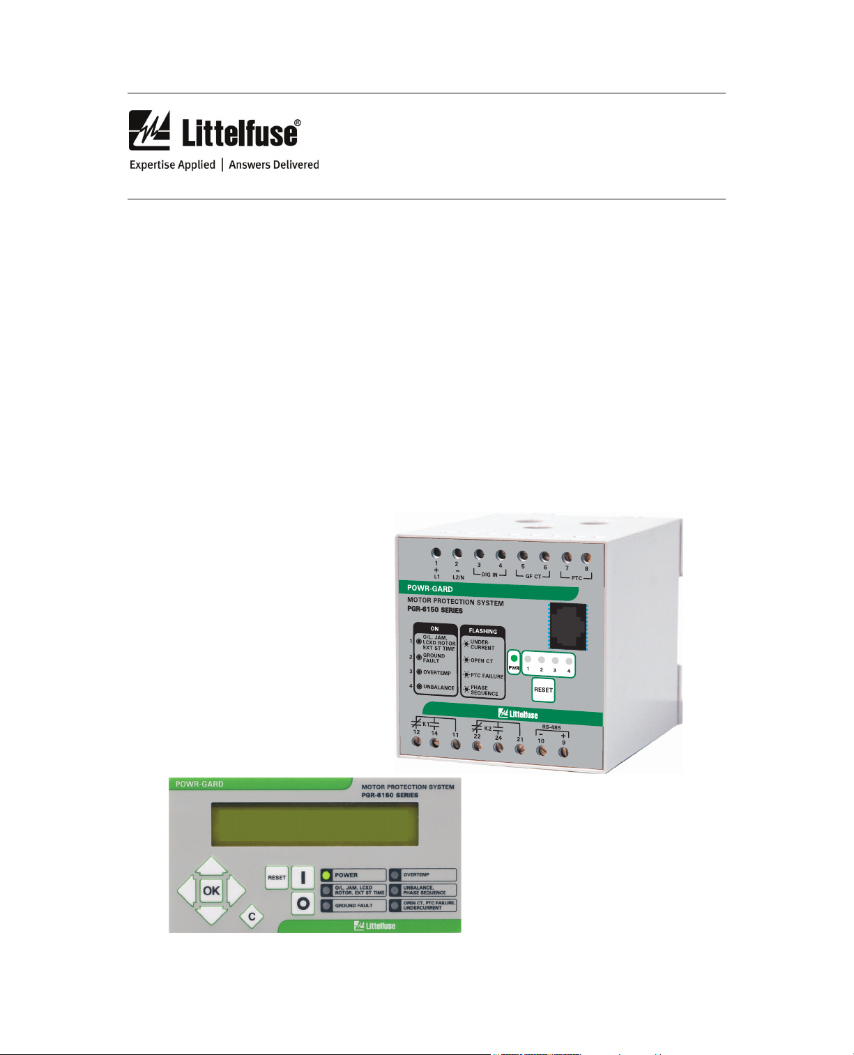
POWR-GARD®
Motor Protection
PGR-6150 SERIES
Motor Protection System
PGR-6150
Motor Protection System
September 29, 2010
REVISION 1

PGR-6150 Motor Protection System Rev. 1
_________________________________________________________________________________

PGR-6150 Motor Protection System Rev. 1
_________________________________________________________________________________
1. GENERAL HANDLING ............................................................................................ 5
1.1. Unpacking and Inspection ............................................................................................................. 5
1.2. Handling Electronic Equipment ..................................................................................................... 5
1.3. Installation ..................................................................................................................................... 5
1.4. Storage ......................................................................................................................................... 5
2. DIMENSIONS ...........................................................................................................
2.1. PGR-6150 ..................................................................................................................................... 6
2.2. PGR-6150-OPI .............................................................................................................................. 7
6
3. CONNECTION DIAGRAMS .....................................................................................
3.1. Direct Connection ......................................................................................................................... 8
3.2. Multiple Pass Connection .............................................................................................................. 8
3.3. External CT Connection ................................................................................................................ 9
3.4. PTC and Ground-Fault Connection ............................................................................................... 9
8
4. PGR-6150 BASE-MODULE TERMINALS ............................................................ 10
5. DESCRIPTION .......................................................................................................
5.1. General ....................................................................................................................................... 11
5.2. Features ...................................................................................................................................... 11
5.2.1. Protection ......................................................................................................................... 11
5.2.2. Metering ........................................................................................................................... 11
5.2.3. Data Logging .................................................................................................................... 11
5.2.4. Inputs and Outputs ........................................................................................................... 12
5.2.5. Operator Interface ............................................................................................................ 12
5.3. Ordering Information ................................................................................................................... 12
11
6. PGR-6150 PROTECTIVE FUNCTIONS AND CONTROL .....................................
6.1. Power Supply .............................................................................................................................. 13
6.2. Protective Functions ................................................................................................................... 13
6.2.1. General Settings ................................................................................................................... 13
6.2.2. Overload ............................................................................................................................... 14
6.2.3. Phase Unbalance .................................................................................................................. 15
6.2.4. Phase Loss ........................................................................................................................... 15
6.2.5. Phase Sequence ................................................................................................................... 16
6.2.6. PTC ....................................................................................................................................... 16
6.2.7. Jam ....................................................................................................................................... 17
6.2.8. Locked rotor .......................................................................................................................... 17
6.2.9. Calculated Definite-Time Ground Fault ................................................................................. 18
6.2.10. Calculated Inverse-Time Ground Fault ................................................................................ 18
6.2.11. Measured Definite-Time Ground Fault ................................................................................ 19
6.2.12. Measured Inverse-Time Ground Fault ................................................................................. 19
6.2.13. Undercurrent ....................................................................................................................... 20
6.2.14. Motor-Start-Up Monitoring ................................................................................................... 20
6.2.15. PGR-6150 Settings Summary ............................................................................................. 21
6.2.16. Overload Curves ................................................................................................................. 24
6.2.17. IEC255-4/BS-142 Curves .................................................................................................... 35
6.3. Monitoring and Control ................................................................................................................ 39
6.3.1. Metering ................................................................................................................................ 39
6.3.2. States .................................................................................................................................... 40
6.3.3. Ground-Fault Current-Transformer Monitoring ...................................................................... 43
6.3.4. Time Delayed PGR-6150 Start .............................................................................................. 43
6.3.5. Reset .................................................................................................................................... 44
6.3.6. Thermal Image Reset ............................................................................................................ 44
6.3.7. Reset/Test Button ................................................................................................................. 44
6.3.8. Reports/Event Records ......................................................................................................... 44
6.3.9. Statistics................................................................................................................................ 45
6.3.10. Commands .......................................................................................................................... 46
13

PGR-6150 Motor Protection System Rev. 1
_________________________________________________________________________________
6.3.11. Digital Input ......................................................................................................................... 46
6.3.12. Outputs ............................................................................................................................... 46
6.3.13. PGR-6150 Base Module LED’s ........................................................................................... 47
6.3.14. Adjustable PGR-6150-OPI LED’s ........................................................................................ 47
6.3.15. Self-Diagnostics .................................................................................................................. 49
6.3.16. Date-Time Synchronization ................................................................................................. 49
6.3.17. RS-485 Communications .................................................................................................... 49
6.3.18. Modbus RTU Protocol ......................................................................................................... 49
6.3.19. User Password .................................................................................................................... 50
6.3.20. PGR-6150 Base Module Test Program ............................................................................... 50
6.3.21. PGR-6150-OPI Test program .............................................................................................. 51
6.3.22. PGR-6150 LCD Contrast .................................................................................................... 51
7. TECHNICAL SPECIFICATIONS AND STANDARDS
7.1. Technical Specifications ............................................................................................................... 52
7.2. Standards .................................................................................................................................... 56
.................................................. 52
8. ACCESSORIES
8.1. Ground-Fault Current Transformer .............................................................................................. 57
8.2. Cable Section.............................................................................................................................. 57
8.3. PGR-6150 Connection Cable ...................................................................................................... 57
....................................................................................................................... 57
9. PGR-6150-OPI OPERATOR INTERFACE
9.1. PGR-6150-OPI Front Panel ........................................................................................................ 58
9.2. LED Indicators ............................................................................................................................ 58
9.3. LCD and Keypad ......................................................................................................................... 58
9.4. Menus ......................................................................................................................................... 58
9.4.1. Standby Mode ...................................................................................................................... 58
9.4.2. Date-Time Menu ................................................................................................................... 59
9.4.3. Version .................................................................................................................................. 59
9.4.4. Communications Menu ......................................................................................................... 60
9.4.5. Test Menu ............................................................................................................................. 60
9.4.6. Functions Menu .................................................................................................................... 61
9.4.7. Metering Menu ...................................................................................................................... 61
9.4.8. States Menu .......................................................................................................................... 62
9.4.9. Settings Menu ....................................................................................................................... 63
9.4.10. Configuration Menu ............................................................................................................. 65
9.4.11. Reports Menu ..................................................................................................................... 65
9.4.12. Command Menu.................................................................................................................. 67
9.4.13. Password Menu .................................................................................................................. 67
............................................... ....................... 58
10. COMMISSIONING ................................................................................................
10.1. Checklist for commissioning ...................................................................................................... 68
10.2. Inspection ................................................................................................................................. 68
10.2.1. Visual inspection ................................................................................................................. 68
10.2.2. Current Transformers .......................................................................................................... 68
10.3. Commissioning ......................................................................................................................... 68
68
11. MODBUS RTU PROTOCOL
11.1. Modbus Package Format .......................................................................................................... 70
11.2. Function Codes ......................................................................................................................... 70
11.3. Error Responses and Exceptions .............................................................................................. 71
11.4. Types of Data ............................................................................................................................ 71
11.5. Data Reading ............................................................................................................................ 72
11.6. Set-Point Writing ....................................................................................................................... 72
11.7. Command ................................................................................................................................. 73
11.8. PGR-6150 Memory Map ........................................................................................................... 74
.............................................................................................. 69
12. APPENDIX
..................................................... ............................ ........................... ................... 89

PGR-6150 Motor Protection System Rev. 1
_________________________________________________________________________________
1. GENERAL HANDLING
1.1. Unpacking and Inspection
The PGR-6150 must only be handled by qualified personnel and special care must be taken to
protect its parts from damage during unpacking and installation.
Inspect the PGR-6150 at delivery to ensure no damage occurred during transport. Inform
Littelfuse Inc. immediately if the product is deemed to be defective.
1.2. Handling Electronic Equipment
Relays contain electronic components that are sensitive to electrostatic discharge.
To ensure that electronic parts are not damaged due to electrostatic discharge, do not remove
the plastic housing.
1.3. Installation
Please read documentation carefully before installing and commissioning the motor protection
system.
Check polarity and voltage before energizing the relay.
The equipment must be used within the stipulated electrical and environmental limits.
Current transformer circuits: Do not open a live CT secondary circuit. The high voltage
NOTE:
produced as a result could damage the insulation and present a personnel hazard.
1.4. Storage
Relays should be stored in a dry and dust-free environment.

PGR-6150 Motor Protection System Rev. 1
_________________________________________________________________________________
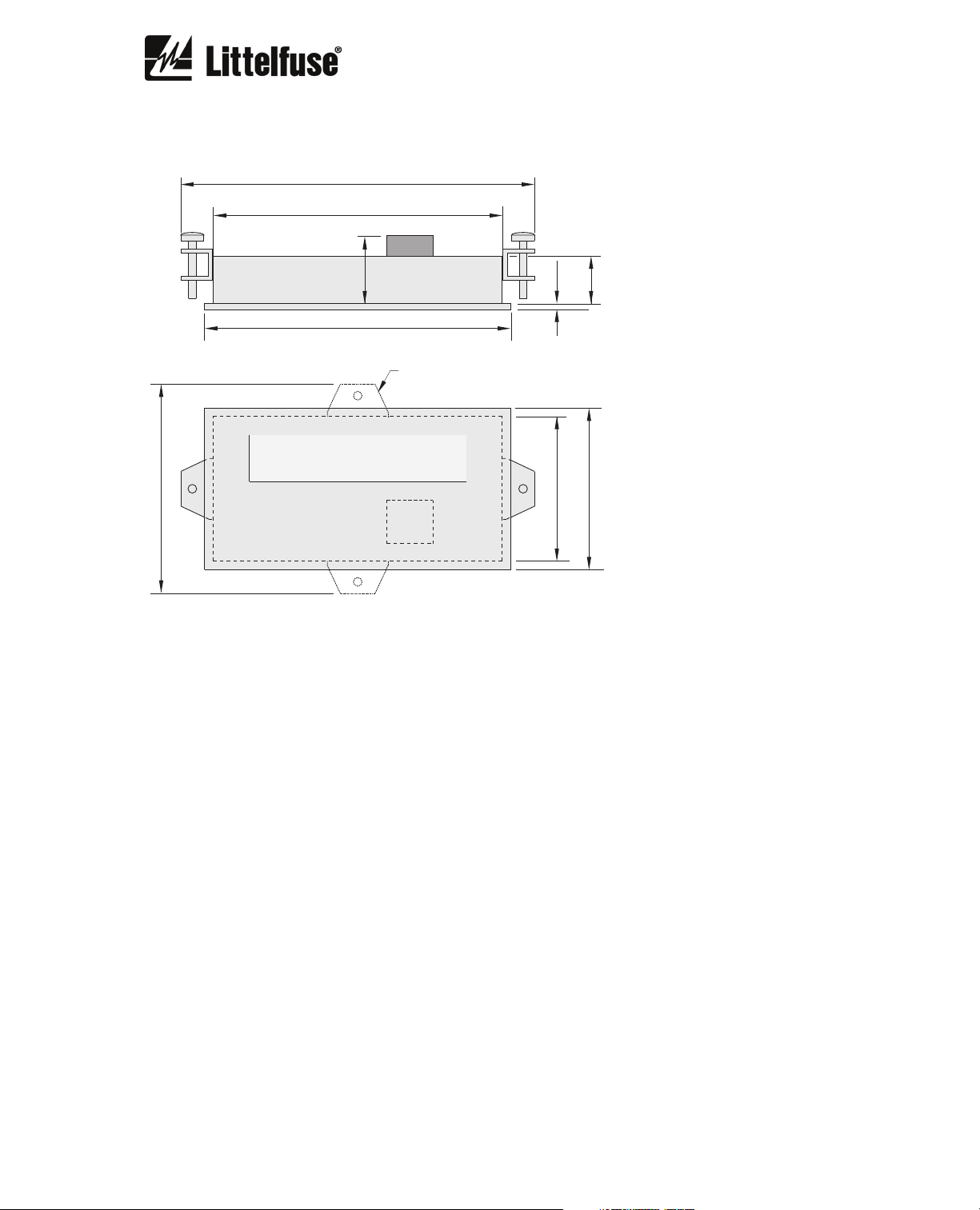
2. DIMENSIONS
2.1. PGR-6150
56.5
(2.22)
14.0
12.0
(0.55)
(0.47)
78.0
(3.07)
ø10
(ø0.39)
TOP VIEW
99.0
(3.90)
33.0
(1.30)
80.0
(3.15)
94.0
(3.70)
SIDE VIEW
35.4
5.0
(0.20)
38.0
(1.39)
45.0
(1.50)
(1.77)
NOTES:
DIMENSIONS IN MILLIMETRES (INCHES).
PGR-6150 Motor Protection System Rev. 1
_________________________________________________________________________________
2.2. PGR-6150-OPI
122.5
(4.82)
100.0
(3.94)
72.5
(2.85)
23.5
(0.93)
106.0
(4.17)
TOP VIEW
FRONT VIEW
ALTERNATE CLAMP
LOCATIONS
2.0
50.0
16.5
(0.08)
56.0
(1.97)
(0.65)
(2.20)
NOTES:
DIMENSIONS IN MILLIMETRES (INCHES).
PGR-6150 Motor Protection System Rev. 1
_________________________________________________________________________________
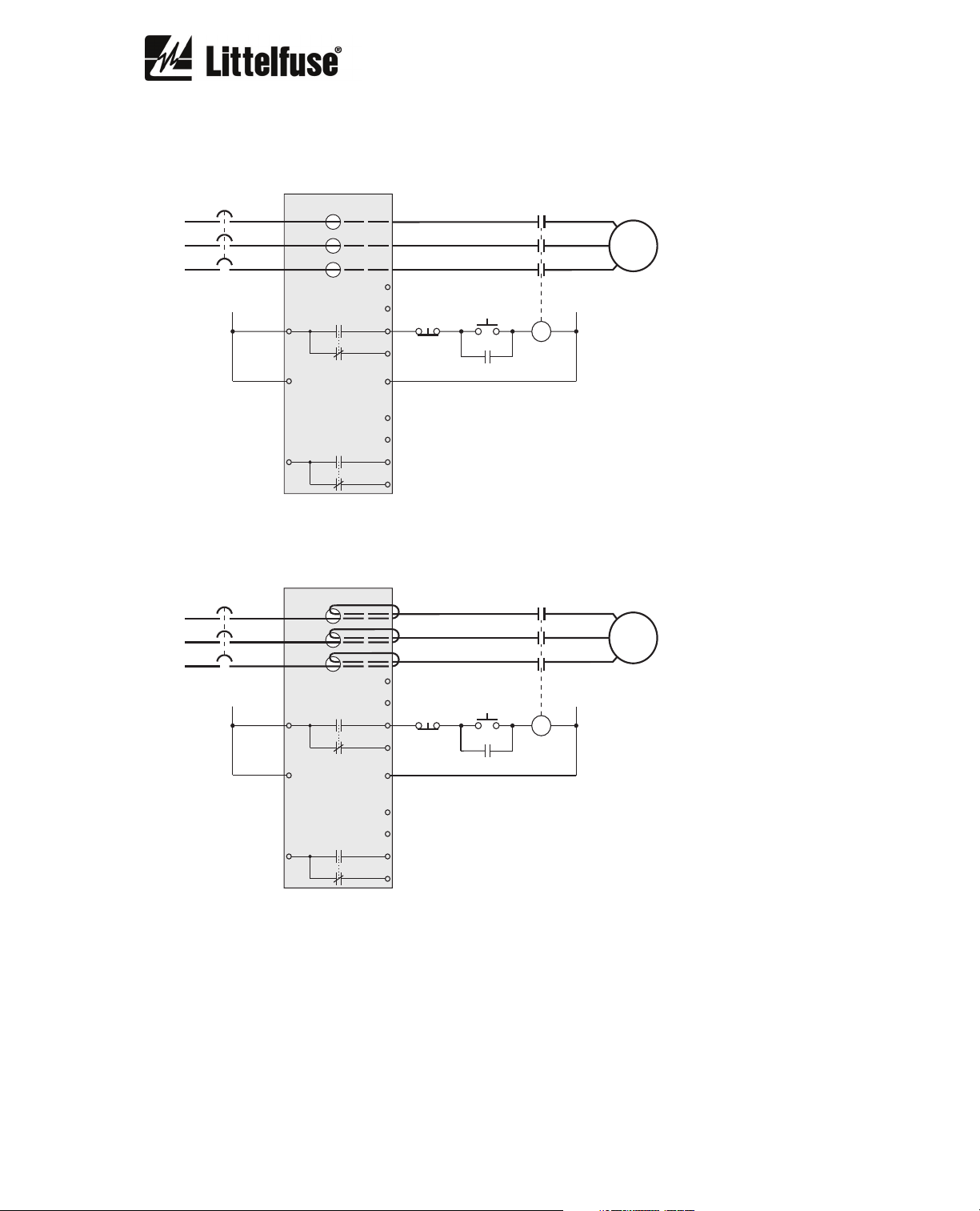
3. CONNECTION DIAGRAMS
3.1. Direct Connection
C
MOTOR
AUX VOLTAGE
SUPPLY
L
TRIP
K1
11
+
L1
PGR-6150
ALARM
K2
21 24
GF CT
PTC
5
6
14
12
-
L2
N
7
8
22
3.2. Multiple Pass Connection
AUX VOLTAGE
SUPPLY
L
TRIP
K1
11
GF CT
5
6
14
12
STOP
STOP
START
C
START
C
N
C
C
MOTOR
N
C
PTC
-
L2
N
7
8
22
+
L1
PGR-6150
ALARM
K2
21 24
For motors with nominal current below the minimum relay set-point value, multiple turns can be
used. Set the value I
and CT Turns Ratio as explained in Section 6.2.1.
B
PGR-6150 Motor Protection System Rev. 1
_________________________________________________________________________________
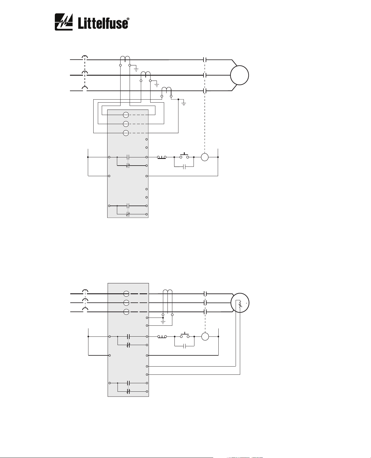
3.3. External CT Connection
CT1
CT2
CT3
5
AUX VOLTAGE
SUPPLY
L
11 14
+
L1
PGR-6150
21 24
TRIP
K1
ALARM
K2
GF CT
PTC
6
STOP
12
-
L2
N
7
8
22
START
C
For motors with nominal current over the maximum relay current set-point value, combine the
relay with current transformers. Set the value IB and CT Turns Ratio as explained in Section
6.2.1.
C
N
C
3.4. PTC and Ground-Fault Connection
GF CT
5
TRIP
K1
ALARM
K2
GF CT
PTC
6
STOP
12
-
L2
N
7
8
22
START
AUX VOLTAGE
SUPPLY
L
11 14
+
L1
PGR-6150
21 24
C
+t
N
C
C
PGR-6150 Motor Protection System Rev. 1
_________________________________________________________________________________
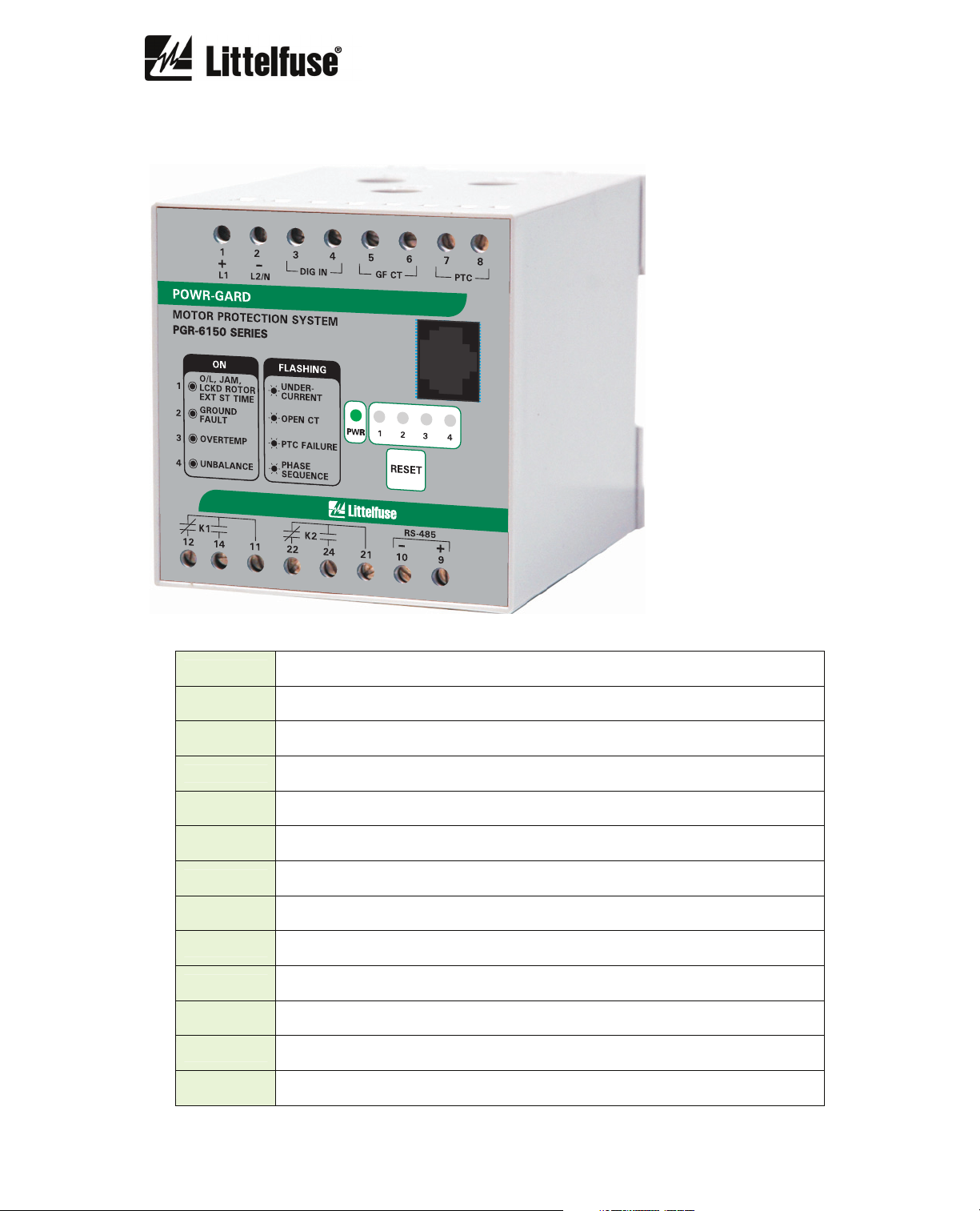
4. PGR-6150 BASE-MODULE TERMINALS
DIG IN
GF CT
PTC PTC temperature sensor connection
+
-
14
12
11
24
22
21
+ L1
24 Vac/dc digital input
Ground-fault current transformer connection
RS-485 connection +
RS-485 connection -
Output K1 contact normally open
Output K1 contact normally closed
Output K1 common
Output K2 contact normally open
Output K2 contact normally closed
Output K2 common
Supply voltage (+ for direct current)
- L2/N
Supply voltage (- for direct current)

PGR-6150 Motor Protection System Rev. 1
_________________________________________________________________________________
5. DESCRIPTION
5.1. General
The PGR-6150 is a modular system that provides integrated protection, metering and data
logging functions. The PGR-6150 base module can operate as a stand-alone unit or with the
operator interface PGR-6150-OPI, the voltage module PGA-0160, and the input/output module
PGA-0180. The base module can be programmed using the PGR-6150-OPI or using SCADA
communications through the RS-485 port.
5.2. Features
5.2.1. Protection
• Overload
• Phase unbalance
• Phase loss
• Phase sequence
• PTC overtemperature
• Jam
• Locked rotor
• Calculated definite-time ground fault
• Calculated inverse-time ground fault
• Measured definite-time ground fault
• Measured inverse-time ground fault
• Undercurrent
• Excessive-start-up time
5.2.2. Metering
• Line currents
• Zero-sequence current
• Ground-fault current
• Thermal image
• Frequency
• Positive-sequence current
• Negative-sequence current
• Average-phase current
5.2.3. Data Logging
• Four fault records
o Date of event
o Line currents
o Frequency
o Overload
o Current unbalance
o PTC overtemperature
o PTC fault
o Jam
o Locked rotor
o Ground-fault current
• Trip counters
o Number of overloads
o Number of overtemperature
o Number of jams
o Number of locked rotors
o Number of ground faults
o Number of startups
• Startup maximum current
• Last startup maximum current
• Last startup average current
• Operating hours

PGR-6150 Motor Protection System Rev. 1
_________________________________________________________________________________
5.2.4. Inputs and Outputs
• One digital input
• One trip output relay
• One alarm output relay
• PTC input
• Ground-fault current transformer input
• Relay closing time delay
• RJ-45 24 Vdc output to PGR-6150-OPI and optional voltage and input/output modules
• RS-485 communications
• 1 Power On LED
• 4 LED status indicators
5.2.5. Operator Interface
• 2 x 20 LCD display
• Display control and programming keys
• 6 programmable LED status indicators
The four status LEDs on the PGR-6150 give indication of faults on the system being monitored.
The system checks both equipment malfunction and external input connections. LED functions
are labelled on the front face of the PGR-6150.
An adjustable power-up timer from 0 to 3600 s allows motors to be started in a staggered
sequence.
The trip and alarm output relay contacts operate in failsafe mode.
The algorithm used to measure the currents calculates the RMS (Root Mean Square) value.
16 samples per cycle are used. The sampling frequency is determined by the system frequency
setting. It can be set to 50, 60 Hz, or variable. The accuracy of the measurement is 2% over the
whole range. The variable frequency sampling is only valid for models with alternating supply as
the alternating supply signal is taken as reference to calculate the line frequency (45 Hz to 65 Hz).
The PGR-6150 information can be accessed from the PGR-6150-OPI or from an RS-485
communications port on terminals 9 and 10, which allows for the PGR-6150 to be included as
part of a SCADA system. The Modbus RTU protocol is used.
Each LED on the PGR-6150-OPI is programmable and can be set as latching or none latching
and/or as flashing or not flashing.
The PGR-6150-OPI is also equipped with a start button and a stop button. To use the start
function “I”, a PGA-0180 Input/Output module is required.
The RESET button can be used to reset the output relays and latched LED’s and to test the
LED’s both on the main module and the operator interface.
5.3. Ordering Information
PGR-6150-24 24/48 Vdc Base Module
PGR-6150-120 120/240 Vac/dc Base Module
PGR-6150-OPI Operator Interface
ACCESSORIES
PGC-6035 Ground-fault current transformer, 35 mm
PGC-6060 Ground-fault current transformer, 60 mm
PGC-6080 Ground-fault current transformer, 80 mm
PGC-6110 Ground-fault current transformer, 110 mm
PGC-6210 Ground-fault current transformer, 210 mm
PGA-0160 Voltage Module
PGA-0180 Input/Output Module

PGR-6150 Motor Protection System Rev. 1
_________________________________________________________________________________
6. PGR-6150 PROTECTIVE FUNCTIONS AND CONTROL
6.1. Power Supply
• The PGR-6150 comes with a 110/240 Vac/dc, 5 W power supply.
The PGR-6150 generates 24 Vdc available through the RJ-45 port to supply auxiliary modules.
6.2. Protective Functions
6.2.1. General Settings
The equipment's general settings are as follows:
General Settings
Description Mínimum Maximum Step Unit Default
Nominal current IB
CT turns ratio 1 2000 1 - 1
Frequency - - 50Hz/60Hz/var Hz 50
Motor start limit 1 8 0.01 X IB 1.5
Motor starting time 1 200 1 s 60
Phase sequence - - ABC/ACB - ABC
PGR-6150 Initial time 0 3600 1 s 0
To protect the motor, the “Nominal current (I
nameplate.
If the “nominal current” is below the minimum relay current set-point value, pass cables through the
relay “n” time. “I
nameplate.
If the “nominal current” is greater than the maximum relay current set-point range, use external current
transformers. “I
divided by the CT Turns Ratio.
The “motor start limit” and "motor starting time" settings are used to adjust motor start up limits. A trip
will result when this limit is exceeded.
“ set value will be “IN x n”, where IN is the nominal current shown on the motor
B
“ set-point value will be the nominal current shown on the motor nameplate
B
4 25 0.01 A 4
)”, must be set to the value stated on the motor
B
,NOTE: For “Motor starting time” choose a value between 1 and 200. It is possible to
deactivate this function by setting the value to 0. A value 0f 0 is not recommended as it may
result in motor damage.
The frequency can be adjusted to 50 Hz, 60 Hz and variable frequency (with the equipment
maintaining measurement accuracy and time within a range of 45 Hz to 65 Hz). The variable
frequency setting applies to models with alternating supply voltage.
The “phase sequence” setting is set to match the phase rotation of the installation.
The “PGR-6150 initial time" is used to delay motor starting in applications where a staggered
start is required.

PGR-6150 Motor Protection System Rev. 1
_________________________________________________________________________________
6.2.2. Overload
The overload function meets international standard IEC 947-4-1 and IEC 255-8.
A mathematically based thermal model is used to simulate the motor's thermal condition. The
model combines two thermal images: A heating image and a cooling image. The heating image
represents the thermal condition of the windings of the stator and rotor, and the cooling image
represents the thermal condition of the motor housing.
This heating and cooling thermal model ensures that the motor is operated in a safe zone.
Time to trip depends on the trip class selected, the circulating current and the previous motor
thermal condition.
The thermal image is calculated based on the following equation:
θ = 100 x (I/I
)2 x (1 – e
t
-t/ζ
) + θ’0 x e
Where:
• I, maximum current of the three phases
trip threshold current
• I
t,
• ζ, thermal constant.
• θ’
, initial thermal condition
0
The trip time comes from the equation:
t = ζ x ln { [(I/I
)2 – (θ’0 / 100) ] / [(I/It)2 - 1] }
t
The trip time accuracy is 5%.
The algorithm uses the maximum current of the three phase currents. If the maximum current is
greater than 15% of the adjusted current I
maximum current is less than 15% of the adjusted current I
applied.
The overload function trips when the thermal image reaches a value of 100%.
A thermal image adjustable level is established to generate an alarm. Should a trip occur, the
overload function is reset when the thermal image drops below the set alarm level.
The thermal constant has the following values:
-t/ζ
, the heating thermal constant is applied. If the
B
, the cooling thermal constant is
B
• ζ heating = 37 x trip class
• ζ cooling = 90 x trip class
If there is external ventilation,
• ζ cooling = (90 x trip class) / 4
•
Overload
Description Minimum Maximum Step Unit Default
Function enabled - - yes/no - yes
Service factor 1 2 0.01 IB 1.15
Trip class - - 5,10,15,20,25,30,35,40,45 - 5
External ventilation - - Yes/No - No
Alarm 20 95 1 % 80

PGR-6150 Motor Protection System Rev. 1
_________________________________________________________________________________
The PGR-6150 allows for overload function settings between 1 and 2 times IB. Note however
that standard IEC-947-4-1 recommends the tap setting to be between 1.05 and 1.20 times I
.
B
6.2.3. Phase Unbalance
The unbalance function is applied on a three phase system made up of three phase currents
(IA, IB, IC). The average current of the three values is taken as reference. The function is
operative when the average current is greater than 10% of the motor set current I
inoperative if the average current is less than 8%.
A dynamic operating band is established based on the average current. An excursion of a phase
current outside of this band for the selected time delay results in an unbalance trip. The band
upper and lower limits are defined by the % unbalance setting. A 5% hysteresis value is applied
for the reset level.
The unbalance reset and activate limits are determined as follows, based on the % unbalance
setting (value d1%):
Upper limit activation I
* (100 + d1)%
average
and becomes
B
Upper limit reset I
Lower limit activation I
Lower limit reset I
* (100 + d1– 5)%
average
* (100 - d1)%
average
* (100 - d1+ 5)%
average
Once the function has been activated, and the phase current drops below the upper reset limit or
rises above the lower reset limit, the function is instantly reset.
Two different time delays apply: one applies when the motor is starting, and the other when the
motor is in operation. As a result, a possible phase loss can be detected in the motor start up
and a fast trip can be executed.
Unbalance
Description Minimum Maximum Step Unit Default
Function enabled - - yes/no - yes
% Unbalance (d1) 5 30 1 %
30
Starting trip time 0.02 20 0.001 s 0.6
Running trip time 0.02 20 0.001 s 5
6.2.4. Phase Loss
The phase loss function is applied on a three phase system made up of three phase currents
(IA, IB, IC). The average current of the three values is taken as reference. The function is
operative if the average current is greater than 10% of the nominal current I
inoperative if the average current is less than 8%.
Based on the average current, a lower limit is established resulting from the % unbalance setting (d2)
and 5% reset hysteresis.
and becomes
B
Lower limit activation Iaverage* (100 – d2)%
Lower limit reset Iaverage* (100 – d2+ 5)%
The criteria is applied to the three phases. If a phase current is less than the lower limit for the
selected time delay, an unbalance trip occurs.

PGR-6150 Motor Protection System Rev. 1
_________________________________________________________________________________
There is only one operating time, regardless of whether the motor is starting up or in operation.
Phase loss
Description Minimum Maximum Step Unit Default
Function enabled - - yes/no - yes
% Unbalance (d2) 10 100 1 %
30
Time 0.02 20 0.001 s 5
6.2.5. Phase Sequence
The sequence function is activated when the phase sequence detected is not in accordance with
the phase sequence setting (ABC/ACB).
The phase sequence detection algorithm is based on the determination of the positive and
negative sequence of the fundamental currents component.
The function is operative if the positive sequence current or the negative sequence current is
greater than 10% of the current I
setting and stops operating if the positive sequence current
B
and the negative sequence current is less than 8%.
Phase sequence
Description Minimum Maximum Step Unit Default
Function enabled - - yes/no - no
Time 0.02 2 0.001 s 0.02
6.2.6. PTC
PTC sensor protection should be applied in the following cases:
• Motors with a high number of starts/stops
• Motor operating at speeds lower than the range it is designed for
• When there is a restricted air supply
• In intermittent operations and/or constant braking
• High air temperatures
PTC sensor short circuit or open circuit and overtemperature are detected. Overtemperature
activates the trip contact, while a PTC sensor open circuit and short circuit activate the alarm
contact. The PTC sensor protection limits are preset and cannot be changed by the user.
Activation resistance Reset resistance
Overtemperature > 3,600 Ω < 1,800 Ω
Short circuit < 20 Ω > 30 Ω
Open circuit > 4,000 Ω < 3,900 Ω

PGR-6150 Motor Protection System Rev. 1
_________________________________________________________________________________
PTC
Description Minimum Maximum Step Unit Default
Function enabled - - yes/no - no
The trip time is 500 ms.
The PTC sensor current is 1 mA and a maximum of 2.3 V is used.
Maximum cold resistance 1,500 Ω
Minimum cold resistance 50 Ω
6.2.7. Jam
This function detects a motor jam and is disabled during motor start up.
JAM
Description Minimum Maximum Step Unit Default
Function enabled - - yes/no - no
Pickup 1 3.5 0.01 I
B
2.5
Operating time 0.02 50 0.001 s 10
This function is enabled after the motor start-up sequence has been completed. See
Section 6.2.14
6.2.8. Locked Rotor
This function detects a locked rotor and is disabled during motor start up.
Locked rotor
Description Minimum Maximum Step Unit Default
Function enabled - - yes/no - no
Pickup 3.5 6 0.01 I
B
Time 1 30 0.001 s 5
This function is enabled after the motor start-up sequence has been completed. See
Section 6.2.14
3.5

PGR-6150 Motor Protection System Rev. 1
_________________________________________________________________________________
6.2.9. Calculated Definite-Time Ground Fault
This function detects motor ground-fault current based on phase currents.
I0>> GF CALC DEF
Description Minimum Maximum Step Unit Default
Function enabled - - yes/no - no
Pickup 0.1 1 0.01 I
Time 0.02 5 0.001 s 1
This function is enabled after the motor start-up sequence has been completed. See
Section 6.2.14
B
0.1
6.2.10. Calculated Inverse-Time Ground Fault
This protection function can be set by using five parameters:
I0> GF CALC INVERSE
Description Minimum Maximum Step Unit Default
Function enabled - - yes/no - no
Curve - - (1*) - Inverse
Dial 0.05 1.25 0.01 - 1.25
Pickup 0.1 1 0.01 IB 1.00
Time 0.02 5 0.001 s 0.2
(1*) Inverse, Very inverse, Extremely inverse, Definite time
If the option "Definite time" is selected for the curve setting, the unit behaves like an
instantaneous overcurrent unit. In this case, the time parameter is active.
If a curve “Inverse”, “Very inverse” or “Extremely inverse” is selected for the curve setting, the trip
time depends on the curve, dial and pickup settings.
If the unit operates as definite time, the function is activated at 100% of the set pickup value, and
it deactivates at 95%.
If the unit operates with a curve, the function is activated at 110% of the set pickup value, and it
deactivates at 100%.
The reset is instantaneous in both cases.
The activation time is accurate to ±5% or ±30 ms, whichever is greater.
The curves used are IEC255-4/BS-142, which are described in Section 6.2.17.

PGR-6150 Motor Protection System Rev. 1
_________________________________________________________________________________
6.2.11. Measured Definite-Time Ground Fault
This option requires a ground-fault current transformer.
IG>> GF MEASURED DEF
Description Minimum Maximum Step Unit Default
Function enabled - - yes/no - no
Pickup 100 15,000 1 mA 100
Time 0.02 5 0.001 s 0,2
This function is enabled after the motor start-up sequence has been completed. See
Section 6.2.14
6.2.12. Measured Inverse-Time Ground Fault
This option requires a ground-fault current transformer.
IG> GF MEASURED INV
Description Minimum Maximum Step Unit Default
Function enabled - - yes/no - no
Curve - - (1*) - Inverse
Dial 0.05 1.25 0.01 - 1.25
Pickup 100 450 1 mA 100
Time 0.02 5 0.001 s 0.2
(1*) Inverse, Very inverse, Extremely inverse, Definite time
If the option "Definite time" is selected for the curve setting, the unit behaves like an
instantaneous overcurrent unit. In this case, the time parameter is active.
If a curve “Inverse”, “Very inverse” or “Extremely inverse” is selected for the curve setting, the
time depends on the curve, dial and pickup settings.
If the unit operates as definite time, the function is activated at 100% of the set pickup value, and
it deactivates at 95%.
If the unit operates with a curve, the function is activated at 110% of the set pickup value, and it
deactivates at 100%. The reset is instantaneous in both cases.
The activation time is accurate to ±5% or ±30ms, whichever is greater.
The curves used are IEC255-4/BS-142, which are described in Section 6.2.17.
PGR-6150 Motor Protection System Rev. 1
_________________________________________________________________________________
6.2.13. Undercurrent
The undercurrent function is not enabled during motor start-up.
I < Undercurrent
Description Minimum Maximum Step Unit Default
Function enabled - - yes/no - no
Pickup 0.3 1 0.01 I
B
0.5
Time 0.02 200 0.001 s 1
Activation is at 100% of the pickup value and reset at 105%. The reset is instantaneous.
The accuracy of the operation time is equal to the set time plus a maximum of 30 ms.
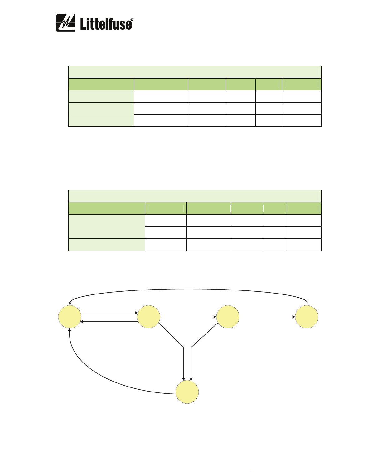
6.2.14. Motor-Start-Up Monitoring
The settings for motor start up are in the General Settings:
Motor start up monitoring
Description Minimum Maximum Step Unit Default
Function enabled - - yes/no - no
Motor start limit 1 8 0.01 IB 1.5
Motor starting time 1 200 0.001 s 60
MOTOR START FLOWCHART
Iaverage < 8%
I
B
Iaverage > 10%
Iaverage < 8%
MOTOR
ON STANDBY
I
B
I
B
MOTOR STARTING
FIRST STEP
Iaverage < 8%
I
average >
I
B
MOTOR
START LIMIT
MOTOR STARTING
TIME EXCEEDED
START TIME
EXCEEDED
I
average <
MOTOR STARTING
SECOND STEP
95%
MOTOR
START LIMIT
The motor is considered to be on standby when the average current is less than 8% of the
nominal current I
average current is greater than 10% of the nominal current I
B. The PGR-6150 switches to the “Motor starting first step” stage when the
B. It switches to “Motor starting
second step" when the average current is greater than the “Motor start limit”, “Motor running”
mode is reached when the average current is less than 95% of the “Motor start limit”.
MOTOR
RUNNING
PGR-6150 Motor Protection System Rev. 1
_________________________________________________________________________________
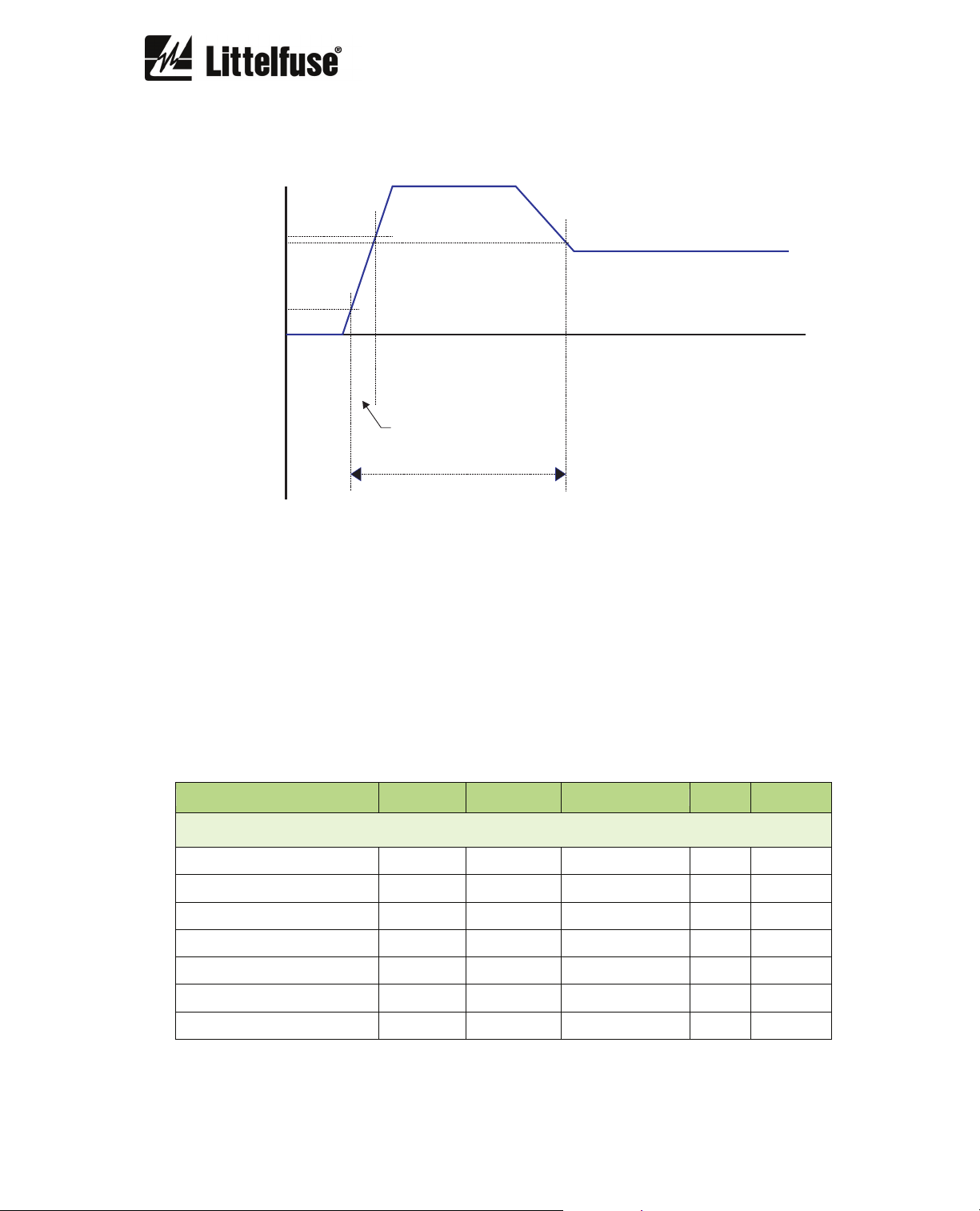
In “Motor first step” and “Motor second step” the start-up time is monitored. If the measured
start-up time is greater than the “Motor starting time” selected, the start up will be aborted due to
a “Start time exceeded” condition.
I
MOTOR START LIMIT
95% MOTOR START LIMIT
10%
I
B
STAND BY
SECOND STEP MOTOR RUNNING
FIRST STEP
MOTOR STARTING TIME
I
average
There are two status bits in the miscellaneous group, related to motor monitoring: “Motor
running” and “Start time exceeded”.
The following statistics are related to motor start up:
• Number of starts
• Maximum start current:
• Last start maximum current:
• Last start average current:
• Measured start time (second step time)
• Number of operating hours (motor in operation)
•
t
6.2.15. PGR-6150 SETTINGS Summary
Description Minimum Maximum Step Unit Default
GENERAL
Nominal current IB 4 25 0.01 A 4
CT turns ratio 1 2,000 1 - 1
Frequency - - 50Hz/60Hz/var (1*) - 50 Hz
Motor start limit 1 8 0.01 IB 1.5
Motor starting time 1 200 1 s 60
Phases sequence - - ABC/ACB - ABC
PGR-6150 initial time 0 3,600 1 s 0

PGR-6150 Motor Protection System Rev. 1
_________________________________________________________________________________
Description Minimum Maximum Step Unit Default
OVERLOAD
Function enabled - - yes/no - yes
Service factor 1 2 0.01 I
Trip class - - 5,10,15,20,25,30,35,40,45 - 5
External ventilation - - Yes/No - No
Alarm 20 95 1 % 80
B
1.15
UNBALANCE
Function enabled - - yes/no - yes
% Unbalance 5 30 1 % 30
Starting trip time 0.02 20 0.001 s 0.6
Running trip time 0.02 20 0.001 s 5
PHASE LOSS
Function enabled - - yes/no - yes
% Unbalance 10 100 1 % 30
Time 0.02 20 0.001 s 5
SEQUENCE
Function enabled - - yes/no - no
Time 0.02 2 0.001 s 0.02
PTC
Function enabled - - yes/no - no
JAM
Function enabled - - yes/no - no
Pickup 1 3.5 0.01 I
Operating time 0.02 50 0.001 s 10
B
2.5
LOCKED ROTOR
Function enabled - - yes/no - no
Pickup 3.5 6 0.01 I
Operating time 1 30 0.001 s 5
B
3.5
I0>> GF CALC DEF
Function enabled - - yes/no - no
Pickup 0.1 1 0.01 I
Operating time 0.02 5 0.001 s 1
B
0.1

PGR-6150 Motor Protection System Rev. 1
_________________________________________________________________________________
Description Minimum Maximum Step Unit Default
I0> GF CALC INVERSE
Function enabled - - yes/no - no
Curve - - (2*) - Inverse
Dial 0.05 1.25 0.01 - 1.25
Pickup 0.1 1 0.01 IB 1.00
Operating time 0.02 5 0.001 s 0.2
IG>> GF MEASURED DEF
Function enabled - - yes/no - no
Pickup 100 15,000 1 mA 100
Operating time 0.02 5 0.001 s 0.2
IG> GF MEASURED INV
Function enabled - - yes/no - no
Curve - - (2*) - Inverse
Dial 0.05 1.25 0.01 - 1.25
Pickup 100 450 1 mA 100
Operating time 0.02 5 0.001 s 0.2
I< UNDERCURRENT
Function enabled - - yes/no - no
Pickup 0.3 1 0.01 IB 0.5
Operating time 0.02 200 0.001 s 1
COMMUNICATION
Modbus address (3*) 1 255 1 - 1
RESET
Enable OPI - - yes/no - no
Enable command - - yes/no - no
Enable input - - yes/no - no
Reset type - - (4*) - Manual
Reset time 0.02 200 0.001 s 0.1
(1*) The frequency can be set to values of 50Hz, 60Hz, and variable frequency in a range of 45 Hz to 65 Hz. The variable
frequency only applies to models with alternating supply voltage.
(2*) Inverse, very inverse, extremely inverse and definite time curves.
(3*) The Modbus address can only be modified from the PGR-6150-OPI. The other settings can be modified from the
PGR-6150-OPI and communications.
(4*) The reset types are: Automatic, Automatic time delay, and Manual.

PGR-6150 Motor Protection System Rev. 1
_________________________________________________________________________________
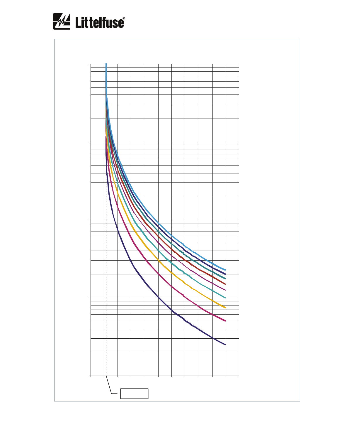
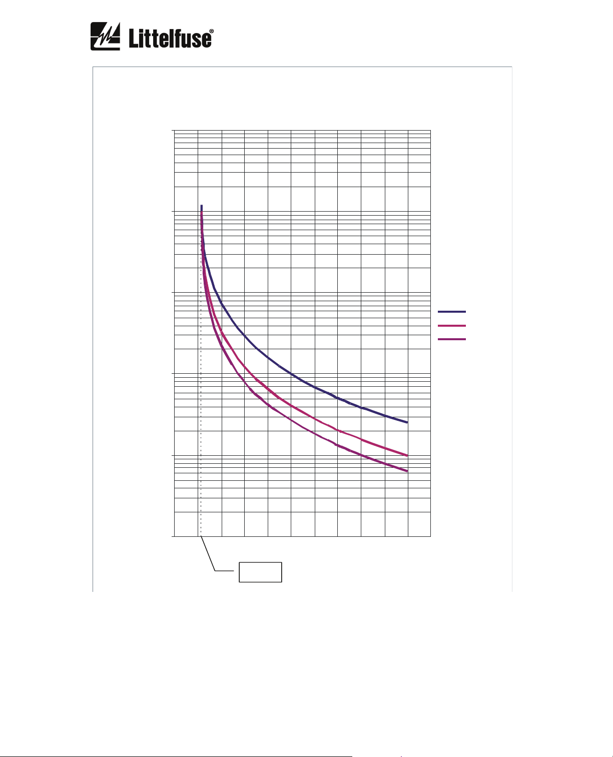
6.2.16. Overload curves
The first graph shows the class 5, 10, 15, 20, 25, 30, 35, 40 and 45 trip curves starting from an
initial thermal condition of 0% (cold).
The following graphs show individually the class 5, 10, 15, 20, 25, 30, 35, 40 and 45 trip curves
with initial thermal conditions of 0% (cold), 60% (hot 60%), 75% (hot 75%).
The 60% hot thermal curves represent the trip time starting from an initial thermal condition of
60% which is reached when I = 0.9 I
The 75% hot thermal curves represents the trip time starting from an initial thermal condition of
75% which is reached when I = I
The x axis represents the current in multiples of I
curves have been represented for an overload pickup current of 1.15 I
and service factor = 1.15.
B
and service factor = 1.15.
B
and the y axis represents time in seconds. The
B
. (service factor = 1.15.)
B
PGR-6150 Motor Protection System Rev. 1
_________________________________________________________________________________
OVERLOAD (cold)
10,000
1,000
100
TIME (s)
CLASS 45
CLASS 40
CLASS 35
CLASS 30
CLASS 25
10
1
01234567891011
x
I
1.15 I
B
CLASS 20
CLASS 15
CLASS 10
CLASS 5
PGR-6150 Motor Protection System Rev. 1
_________________________________________________________________________________
OVERLOAD CLASS 5
10,000.0
1,000.0
100.0
COLD
HOT 60%
HOT 75%
TIME (s)
10.0
1.0
Hot 60% I = 0.9IB
Hot 75% I = I
B
0.1
0.0 1.0 2.0 3.0 4.0 5.0 6.0 7.0 8.0 9.0 1 0.0 11.0
I
x
1.15 I
B
B
PGR-6150 Motor Protection System Rev. 1
I
_________________________________________________________________________________
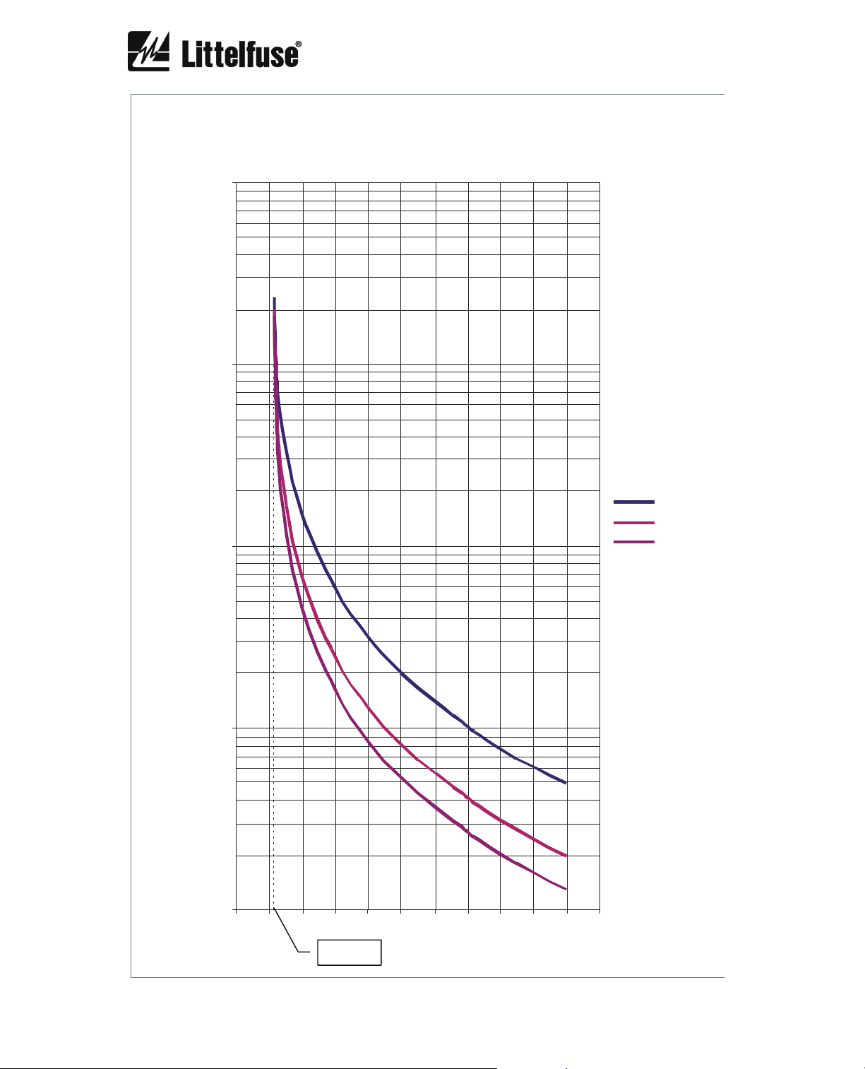
OVERLOAD CLASS 10
10,000 .0
1,000.0
TIME (s)
100.0
10.0
1.0
0.0 1.0 2.0 3.0 4 .0 5.0 6.0 7.0 8.0 9.0 10.0 11.0
COLD
HOT 60%
HOT 75%
Hot 60% I = 0.9 I
Hot 75% I = I
B
B
I
1.15
B
x
B
PGR-6150 Motor Protection System Rev. 1
_________________________________________________________________________________
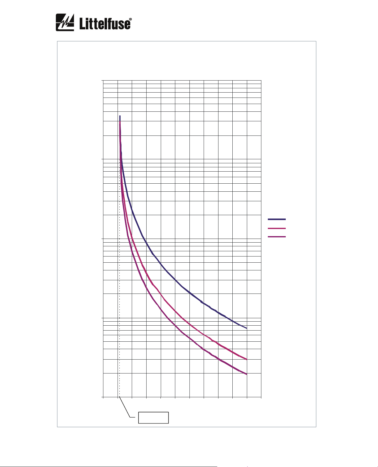
OVERLOAD CLASS 15
10,000.0
1,000.0
TIME (s)
100.0
10.0
1.0
0.0 1.0 2.0 3.0 4.0 5.0 6.0 7.0 8.0 9.0 10.0 11.0
COLD
HOT 60%
HOT 75%
Hot 60% I = 0.9 I
Hot 75% I = I
B
B
I
x
1.15 I
B
B
 Loading...