

Littelfuse PGR-6100 Users Manual
Ground-Fault & Insulation Monitor
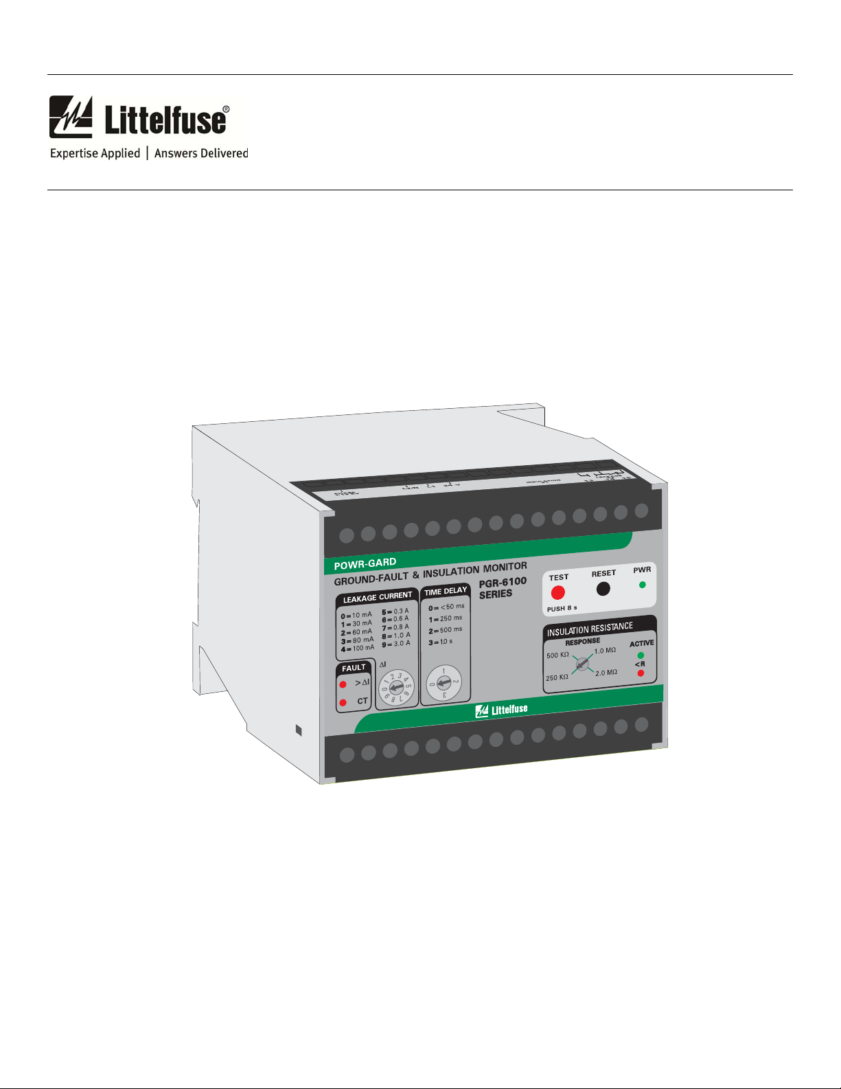
PGR-6100
PGR-6100 MANUAL
GROUND-FAULT & INSULATION MONITOR
Revision 2-B-111014
Document Number: PM-1100-EN
Printed in Canada.
Copyright © 2014 by Littelfuse, Inc.
All rights reserved.

Page i
PGR-6100 Ground-Fault & Insulation Monitor Rev. 2-B-111014
This page intentionally left blank.

Page ii
PGR-6100 Ground-Fault & Insulation Monitor Rev. 2-B-111014
TABLE OF CONTENTS
SECTION PAGE
1 General ....................................................................... 1
2 Operation ................................................................... 1
2.1 Output Relay Operating Mode ................................... 1
2.2 PGR-6100 Operating Mode ....................................... 1
2.2.1 Online Operation ............................................ 1
2.2.2 Offline Operation ........................................... 1
2.3 Front-Panel Controls .................................................. 1
2.3.1 Ground-Fault Trip Level ................................ 1
2.3.2 Ground-Fault Trip Time ................................ 1
2.3.3 Insulation Resistance Response ..................... 1
2.3.4 Reset ................................................................ 1
2.3.5 Test .................................................................. 2
2.4 Front-Panel Indication ................................................ 2
2.4.1 Power .............................................................. 2
2.4.2 >I .................................................................. 2
2.4.3 CT .................................................................. 2
2.4.4 Active .............................................................. 2
2.4.5 <R .................................................................... 2
2.5 Analog Outputs ........................................................... 2
2.5.1 Out I ................................................................ 2
2.5.2 Out R ............................................................... 2
2.6 Remote Test ................................................................ 2
2.7 Remote Reset .............................................................. 2
2.8 CT Verification ........................................................... 2
3 Installation ................................................................. 2
3.1 PGH-5000 and PGH-6000 ......................................... 4
4 Technical Specifications .......................................... 8
4.1 PGR-6100 ................................................................... 8
4.1.1 PGR-6100 Online Operation ......................... 8
4.1.2 PGR-6100 Offline Operation ......................... 8
4.2 PGH High Tension Couplers ..................................... 9
5 Ordering Information .............................................. 9
6 Tests ........................................................................ 10
6.1 Ground-Fault Test .................................................... 10
6.2 Insulation Test .......................................................... 11
Appendix A PGR-6100 Revision History ........................ 12
FIGURE PAGE
1 PGR-6100 Outline and Mounting Details ................. 3
2 Typical Connection Diagram ..................................... 4
3 PGC-5000-Series Current Sensors ............................ 5
4 PGH-5000 Outline and Mounting Details ................ 6
5 PGH-6000 Outline and Mounting Details ................ 7
6 PGA-0500 Analog Percent Current Meter ................ 9
7 PGA-0510 Analog Ohm Meter ............................... 10
8 Ground-Fault-Test Circuit ....................................... 11
T
ABLE PAGE
1 Ground-Fault-Test Record ....................................... 11
Specifications are subject to change without notice.
Littelfuse, Inc. is not liable for contingent or
consequential damages, or for expenses sustained as a
result of incorrect application, incorrect adjustment, or a
malfunction.
LIST OF FIGURES
LIST OF TABLES
DISCLAIMER

Page iii
PGR-6100 Ground-Fault & Insulation Monitor Rev. 2-B-111014
This page intentionally left blank.

Page 1
PGR-6100 Ground-Fault & Insulation Monitor Rev. 2-B-111014
1. GENERAL
2.2.1 O
NLINE OPERATION
In Online mode, the PGR-6100 in conjunction with a
The PGR-6100 Ground-Fault & Insulation Monitor can
detect a motor ground fault whether the motor is running
(Online mode) or stopped (Offline mode), and can be
used to protect a motor supplied by a solidly grounded,
resistance-grounded, or ungrounded system. On an
ungrounded system, use only the Offline mode.
On grounded systems, a current transformer (CT) is
used to detect ground-fault current as low as 10 mA when
the motor is running. Insulation resistance is measured to
detect a fault when the motor is stopped. Online or
Offline mode is selected with a digital input connected to
a starter auxiliary contact.
In the Online mode, ground-fault current is sensed by a
PGC-5000-series zero-sequence CT. The trip level of the
ground-fault circuit is selectable from 10 mA to 3 A. Trip
time is selectable from <50 ms to 10 s. Additional
current-detection features include harmonic filtering, a
relay output that can operate in the fail-safe or non-failsafe mode, CT-connection detection, LED trip, LED
power, and LED open-CT indication, autoreset or
latching trips with front-panel and remote reset, a test
button, and a 0- to 1-mA-analog output.
In the Offline mode, insulation-resistance monitoring is
enabled with a selectable 250-k to 2-M alarm-setting
range. Additional insulation-monitoring features include
a relay output that can operate in the fail-safe or non-failsafe mode, LED active and low-resistance indication, and
a 0- to 1-mA-analog output.
The PGR-6100 can be directly connected to a supply
up to 1.3 kV. For systems from 1.3 to 5 kV, use a PGH5000 High Tension Coupler. For systems from 5 kV to
6 kV, use a PGH-6000 High Tension Coupler.
2. OPERATION
2.1 OUTPUT RELAY OPERATING MODE
In the fail-safe mode the output relays energize when
power is applied and the ground-fault and insulationresistance circuits are not tripped. Fail-safe mode is the
factory setting.
For non-fail-safe operation connect terminals 19-20
and 22-23. The respective output relay will energize
when a fault occurs. See Fig. 2.
2.2 PGR-6100 O
Connect terminals 27 and 28 to a normally closed
(Form B) auxiliary starter contact. When terminals 27
PERATING MODE
PGC-5000-series zero-sequence current sensor operates
as a ground-fault relay.
2.2.2 O
FFLINE OPERATION
The PGR-6100 changes mode by means of an auxiliary
contact on the main contactor when the motor is off. It
becomes an insulation-resistance monitor and imposes a
small dc voltage to the motor windings and supply cable
from the motor starter. Leakage to ground is detected.
RONT-PANEL CONTROLS
2.3 F
2.3.1 G
ROUND-FAULT TRIP LEVEL
The Leakage Current I selector switch is used to set the
ground-fault trip level from 10 mA to 3 A. For groundfault detection, the switch setting must be set substantially
below the prospective ground-fault current. To avoid
sympathetic tripping, the switch setting must be above the
charging current of the protected feeder.
2.3.2 G
ROUND-FAULT TRIP TIME
The PGR-6100 has a definite-time trip characteristic.
In tripping systems, the TIME DELAY selector is used to
set the ground-fault trip time for coordination with
upstream and downstream ground-fault devices. Trip time
is selectable from < 50 ms to 1.0 s. Coordination requires
the same trip level for all ground-fault devices in a system
and the trip time to progressively increase upstream. The
amount of equipment removed from the system will be a
minimum if the first ground-fault device to operate is the
one immediately upstream from the fault.
2.3.3 I
NSULATION RESISTANCE RESPONSE
The PGR-6100 insulation resistance function has an
adjustable alarm range of 250 k to 2 M. There is no
selectable time delay. The unit will operate in less than
three seconds.
2.3.4 R
ESET
The front-panel RESET button is used to reset latching
trips. After a fault has been cleared, cycling the supply
voltage will also reset the PGR-6100.
To use the PGR-6100 in autoreset mode, connect
terminals 18-19 and 21-22. See Fig. 2.
The reset function is not instantaneous. Press the RESET
button for several seconds.
and 28 are open, Online mode is selected (insulation
monitoring off). When terminals 27 and 28 are connected,
Offline mode is selected (insulation monitoring active).
 Loading...