

Littelfuse PGR-4300 Users Manual
Generator Ground-Fault Relay
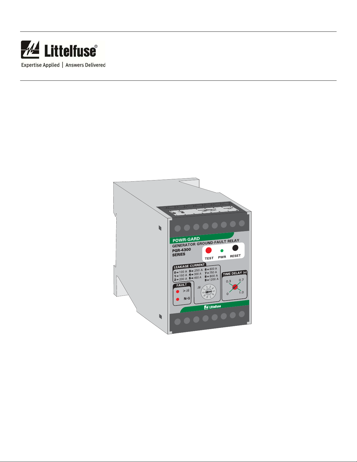
PGR-4300
PGR-4300 MANUAL
GENERATOR GROUND-FAULT RELAY
REVISION 3-A-073115
Document Number: PM-1030-EN
Printed in Canada.
Copyright © 2015 by Littelfuse, Inc.
All rights reserved.

Page i
PGR-4300 Generator Ground-Fault Relay Rev. 3-A-073115
This page intentionally left blank.

Page ii
TABLE OF CONTENTS
SECTION PAGE
1 General ....................................................................... 1
2 Operation ................................................................... 1
2.1 System Selection ........................................................ 1
2.2 Front-Panel Controls .................................................. 1
2.2.1 Ground-Fault Trip Level ................................ 1
2.2.2 Ground-Fault Trip Time ................................ 1
2.2.3 Reset ................................................................ 1
2.2.4 Test .................................................................. 1
2.3 Front-Panel Indication ................................................ 1
2.3.1 Power .............................................................. 1
2.3.2 >I .................................................................. 1
2.3.3 N-G ................................................................ 1
2.4 Analog Output ............................................................ 3
2.5 Remote Reset .............................................................. 3
2.6 Relay Operating Mode ............................................... 3
3 Installation ................................................................. 3
4 Technical Specifications .......................................... 7
5 Ordering Information .............................................. 7
6 Warranty ................................................................... 7
7 Performance Test ..................................................... 8
Appendix A PGR-4300 Revision History .......................... 9
PGR-4300 Generator Ground-Fault Relay Rev. 3-A-073115
LIST OF FIGURES
FIGURE PAGE
1 PGR-4300 Outline and Mounting Details ................. 2
2 Three-Pole Transfer Switch Typical Connection
Diagram ...................................................................... 3
3 Four-Pole Transfer Switch Typical Connection
Diagram ...................................................................... 4
4 PGA-0500 Analog Percent Current Meter ................ 4
5 PMA-55 Panel-Mount Adapter ................................. 5
6 PMA-60 Panel-Mount Adapter ................................. 6
7 PGR-4300 Performance Test Circuit ......................... 8
LIST OF TABLES
TABLE PAGE
1 Ground-Fault-Test Record ......................................... 8
DISCLAIMER
Specifications are subject to change without notice.
Littelfuse, Inc. is not liable for contingent or
consequential damages, or for expenses sustained as a
result of incorrect application, incorrect adjustment, or a
malfunction.

Page iii
PGR-4300 Generator Ground-Fault Relay Rev. 3-A-073115
This page intentionally left blank.

Page 1
PGR-4300 Generator Ground-Fault Relay Rev. 3-A-073115
RONT-PANEL CONTROLS
1. GENERAL
2.2 F
2.2.1 GROUND-FAULT TRIP LEVEL
The PGR-4300 Generator Ground-Fault Relay
provides a simple method for detecting a ground-fault
condition on a generator-supplied system, without the
need for a current transformer. It continuously monitors
for ground-fault current and neutral-to-ground continuity.
It can be applied on a three phase system with a threepole or four-pole transfer switch and can be used in a
dedicated generator application.
In a three-pole transfer-switch application, the
generator neutral and system neutral are connected to
ground at the service entrance. The connection between
the generator neutral and service-entrance ground is
assumed to have a resistance of 2 mΩ and voltage across
this conductor is measured to calculate ground-fault
current. See Fig. 2. The selection of a neutral-bonding
conductor can be made using NEC 250.102(D) and
250.122, and calculating the conductor length needed for
a 2 mΩ resistance.
In a four-pole transfer-switch application the ground
connection to earth is at the generator. See Fig. 3. The
resistance of the bonding cable between the generator
neutral and ground is assumed to have a resistance of 0.2
mΩ. The voltage across this conductor is measured to
calculate ground-fault current. A 0.9 m (3’) length of
AWG 3/0 copper cable is recommended per NEC
250.102(C).
In a dedicated generator application, to ensure proper
operation of the PGR-4300 there can be only one ground
connection to earth. If the earth connection is at the
generator, configure the PGR-4300 as a four-pole system.
If the earth connection is at the load or service entrance,
configure as a three-pole system.
The PGR-4300 has one output relay with normally
open / normally closed contacts for use in a control
circuit. Additional features include LED trip and power
indication, front-panel and remote reset, 0- to 1-mA
analog output, a level-selector switch, and a trip-time
setting.
An epoxy-filled enclosure provides the PGR-4300
protection against vibration.
The trip level of the ground-fault circuit is switch
selectable from 100 to 1,200 A. Trip time is selectable
from 0 to 1.0 s.
2. OPERATION
YSTEM SELECTION
2.1 S
For a four-pole system, connect terminals 11 and 12.
For a three-pole system, leave terminals 11 and 12 open.
The I selector switch is used to set the ground-fault trip
level from 100 to 1,200 A. Unbalanced single-phase
currents returning through the bonding conductor will
appear as ground-fault current. To avoid nuisance
tripping, set the trip-level setting above these currents.
2.2.2 G
ROUND-FAULT TRIP TIME
The PGR-4300 has a definite-time trip characteristic.
In tripping systems, the TIME DELAY selector is used to
set the ground-fault trip time for coordination with
downstream ground-fault devices. Trip time is selectable
from 0 to 1.0 s. Coordination requires the same trip level
for all ground-fault devices in a system and the trip time
to progressively increase upstream. The amount of
equipment removed from the system will be a minimum if
the first ground-fault device to operate is the one
immediately upstream from the fault.
2.2.3 R
ESET
The front-panel RESET button is used to reset latching
trips. When remote-reset terminals 4 and 5 are
connected, a trip remains latched until the RESET button
is pressed or the remote-reset terminals are opened.
Cycling the supply voltage will also reset the PGR-4300.
If the remote-reset terminals are not connected, the
PGR-4300 operates in the non-latching mode and a trip
will reset when the fault is removed.
2.2.4 T
EST
The TEST button is used to test the ground-fault
circuit, the indication, and the output relay. When the
TEST button is pressed, the circuit will trip, the >ΔI LED
will light, the output relay will energize, and the analog
output will indicate full scale (1 mA).
2.3 FRONT-PANEL INDICA TION
2.3.1 POWER
The green LED labelled PWR indicates the presence of
supply voltage.
2.3.2 >I
The red LED labelled >I indicates a ground-fault trip. It
also lights when the neutral connection is open.
2.3.3 N-G
The red LED labelled N-G indicates a neutral-toground trip. When continuity between the generator
neutral and ground is broken, the N-G and >I LED’s will
be on and the output relay will be energized.
 Loading...