

Page 1
2.24 +/- 0.18
(0.088" +/- 0.007")
2.54
(0.100")
0.15 +/- 0.08
(0.006 +/- 0.003")
TYP
1.09
(0.043")
1.91
(0.075")
0.91
(0.036")
TYP
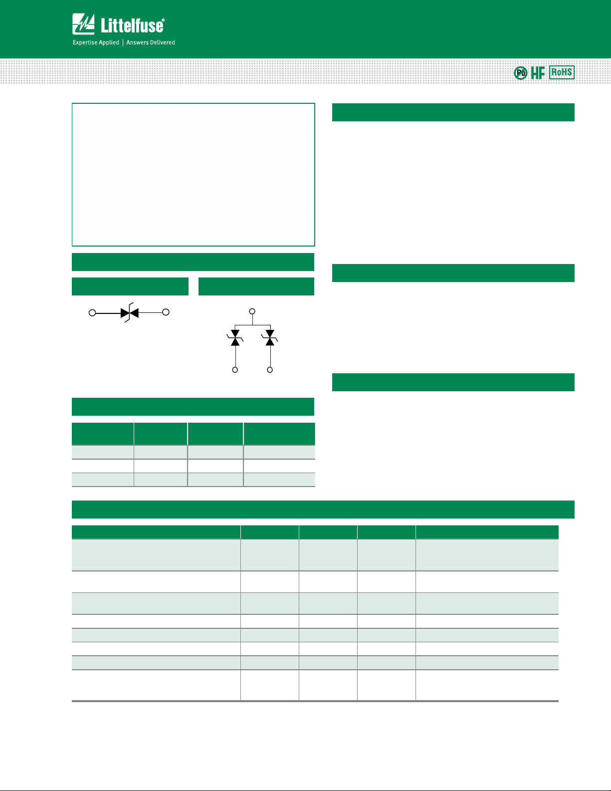
Equivalent Circuit
3
Wave Solder
1.27
(0.050")
1.27
(0.050")
2.29
(0.090")
0.64
(0.025")
1.02 (0.040")
Reflow Solder
Wave Solder
1.27 (0.050")
0.76 (0.030")
3.30
(0.130")
1.27 (0.050")
0.51 (0.020")
0.76 (0.030") 0.76 (0.030")
1.66 +/- 0.06
(0.066" +/- 0.003”)
0.15 +/- 0.08
(0.006" +/- 0.003”)
0.84 +/- 0.05
(0.033" +/- 0.002”)
0.36 (0.014")
0.43 +/- 0.18
(0.017" +/- 0.007”)
Equivalent Circuit
2
1
PGB1 Series
Equivalent Circuits
0402 and 0603 Devices
PULSE-GUARD® ESD Suppressors
Surface Mount Polymeric Electrostatic Discharge Suppressors
Description
PULSE-GUARD ESD Suppressors help protect sensitive
electronic equipment against electrostatic discharge (ESD).
They supplement the on-chip protection of integrated
circuitry and are best suited for low-voltage, high-speed
applications where low capacitance is important. Data ports
utilizing such high-speed protocols as USB 2.0, IEEE1394,
HDMI and DVI can benefit from this new technology.
PULSE-GUARD suppressors use polymer composite
materials to suppress fast-rising ESD transients (as specified
in IEC 61000-4-2), while adding virtually no capacitance to
the circuit.
Features
SOT23 Device
• RoHS compliant, lead-free
and available halogen-free
• Ultra-low capacitance
• Low leakage current
• Fast response time
• Bi-directional
• Withstands multiple
ESD strikes
• Compatible with
pick-and-place processes
• Available in 1000, 3000,
5000 and 10000 piece
reels (EIA-RS481)
Product Characteristics
Part Number
PGB1010603 1 0603 Ye s
PGB102ST23 2 SOT23 Ye s
Electrical Characteristics
Specification PGB1010402 PGB1010603 PGB102ST23 Notes
ESD Capability:
IEC 61000-4-2 Contact Discharge (typical)
IEC 61000-4-2 Air Discharge (maximum)
Peak Voltage (typical) 1000V 500V 500V
Clamping Voltage (typical) 250V 150V 150V
PGB1010402 1 0402 No
Rated Voltage (maximum) 12VDC 24VDC 24VDC
Capacitance (typical) 0.04 pF 0.06 pF 0.12 pF Measured at 250 MHz
Response Time <1nS <1nS <1nS
Leakage Current (typical) <1nA (12 VDC) <1nA (6 VDC) <1nA (6 VDC)
ESD Pulse Withstand
Notes: 1. PGB1 0402 product not offered as Halogen Free. See PGB2 series 0402 product instead (http://www.littelfuse.com/series/PGB2010402.html).
2. Testing performed on Littelfuse test setup as described in Typical Test Setup Section on page 4 of this document.
Lines
Protected
Component
Package
1
Halogen-Free
pulses min
2
Available as
1
8kV
15kV
100
Applications
• HDTV Hardware
• Laptop/Desktop
Computer
• Network Hardware
• Computer Peripherals
8kV
15kV
1000
pulses min
8kV
15kV
1000
pulses min
• Digital Camera
• External Storage
• Set-Top Box
• Antenna
Measured per IEC 61000-4-2
8kV Contact Discharge
Measured per IEC 61000-4-2
8kV Contact Discharge2, at 25 nsec.
Some shifting in characteristics may
occur when tested over multiple
pulses at a very rapid rate
2
1
Specifications are subject to change without notice.
© 2013 Littelfuse, Inc.
Revised: 12/26/13
Page 2
PULSE-GUARD® ESD Suppressors
** Note: 1,000 fF = 1 pF
Frequency (GHz)
Capacitance (fF)
60
50
1.0
70
40
2.01.50.5
0
200
400
600
800
1000
1200
-250 25 50 75 100 125 150 175
PGB1010603
PGB102ST23
PGB1010402
Time (ns)
Voltage (V)
0.01
0.10
1.00
100 1,000 10,000
Frequency (MHz)
PGB1040805
PGB1010402
PGB1010603
PGB102ST23
0
200
400
600
800
1000
1200
-250 25 50 75 100125 150 175
PGB1010603
PGB102ST23
PGB1040805
PGB1010402
Time (ns)
Voltage (V)
0
200
400
600
800
1000
1200
-250 25 50 75 100125 150 175
PGB1010603
PGB102ST23
PGB1040805
PGB1010402
Time (ns)
Voltage (V)
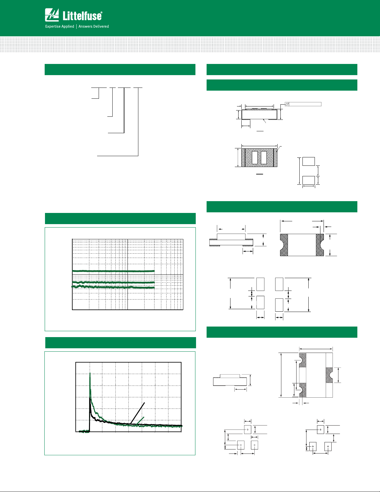
Reference Dimensions:
Note: For wave solder, increase the spacing
in both the horizontal and vertical dimensions by
0.254 (.010") where denoted by an asterisk (*)
Reference Dimensions:
Note:
The device has two rectangular ink marking
to improve its identification by Automated
Optical Inspection systems
0.99 +/- 0.05
(0.039" +/- 0.002")
0.25
(0.010")
0.24 +/- 0.09
(0.009" +/- 0.004")
0.71 (0.028”)
0.86 (0.034”)
0.31 +/- 0.08
(0.012" +/- 0.003")
0.51 +/- 0.05
(0.020" +/- 0.002")
Termination
SIDE
0.1 +/- 0.09
(0.004" +/- 0.004")
Body
TOP
0 - 0.025 (0” - 0.0010”)
0.56
(0.022")
Recommended for
reflow soldering only
0.38
(0.015")
.58
(0.023")
1.55
(0.061")
Reflow Solder
PGB1 01 0603 MR
Surface Mount Polymeric Electrostatic Discharge Suppressors
Part Numbering System
LEAD-FREE
PULSE-GUARD®
ESD SUPPRESSORS
LINES PROTECTED:
01 = 1 line
02 = 2 lines
DEVICE SIZE CODE:
0402 = 0402 (1005)*
0603 = 0603 (1608)
ST23 = SOT23
QUANTITY &
PACKAGING CODE:
MR = 1000 pieces, tape & reel
WR = 3000 pieces, tape & reel
NR = 5000 pieces, tape & reel
KR = 10,000 pieces, tape & reel
*Note: PGB1 0402 product not available as Halogen Free item.
See PGB2 0402 product instead, part number PGB2010402KRHF
(http://www.littelfuse.com/series/PGB2010402.html).
Typical Device Capacitance
1.00
0.10
Capacitance (pF)
0.01
Typical ESD Response
Voltage (V)
2
1200
1000
100 1,000 10,000
800
600
400
200
0
-250 25 50 75 100 125 150 175
Frequency (MHz)
PGB1010603
PGB102ST23
PGB1010402
Time (ns)
Dimensions
0402 Device
Dimensions: mm (inch)
0603 Device
Dimensions: mm (inch)
1.04
(0.041") REF
0.43 +/- 0.18
PGB102ST23
PGB1010603
PGB1010402
(0.017" +/- 0.007”)
Reflow Solder
0.51 (0.020")
3.05
(0.120")
0.76 (0.030") 0.76 (0.030")
1.27 (0.050")
SOT23 Device
Dimensions: mm (inch)
0.81
(0.032")
TYP
Reflow Solder
1.02 (0.040")
2.29
1.02 (0.040")
(0.090")
0.64
(0.025")
0.51
(0.020")
(0.080")
0.36 (0.014")
3.00 +/- 0.20
(0.118" +/- 0.008")
0.69 +/- 0.10
(0.027" +/- 0.004)
1.27
(0.050")
1.02 (0.040")
2.03
1.66 +/- 0.06
(0.066" +/- 0.003”)
0.84 +/- 0.05
(0.033" +/- 0.002”)
Wave Solder
0.76 (0.030")
1.27 (0.050")
(0.075")
0.91
(0.036")
TYP
0.15 +/- 0.08
(0.006 +/- 0.003")
TYP
1.91
3.30
(0.130")
2.24 +/- 0.18
(0.088" +/- 0.007")
Wave Solder
1.02 (0.040")
2.54
(0.100")
0.64
(0.025")
Specifications are subject to change without notice.
2.29
(0.090")
© 2013 Littelfuse, Inc.
0.15 +/- 0.08
(0.006" +/- 0.003”)
1.09
(0.043")
1.27
(0.050")
1.27
(0.050")
Revised: 12/26/13
Page 3

PULSE-GUARD® ESD Suppressors
o
Surface Mount Polymeric Electrostatic Discharge Suppressors
Physical Specifications
Materials
Solderability MIL-STD-202, Method 208
Soldering
Parameters
Body: Glass Epoxy
Terminations: Copper/Nickel/Tin
Wave solder - 260°C, 10 seconds maximum
Reow solder - 260°C, 30 seconds maximum
Design Consideration
Because of the fast rise-time of the ESD transient, proper
placement of PULSE-GUARD suppressors are a key design
consideration to achieving optimal ESD suppression. The
devices should be placed on the circuit board as close to the
source of the ESD transient as possible. Install PULSE-GUARD
suppressors (connected from signal/data line to ground)
directly behind the connector so that they are the first boardlevel circuit component encountered by the ESD transient.
Soldering Parameters
Environmental Specifications
Operating Temperature -65°C to +125°C
0402 series:
Moisture Resistance
Thermal Shock
Vibration
Chemical Resistance MIL-STD-202, Method 215
Solder Leach Resistance and
Terminal Adhesion
40°C, 95% RH, 1000 hours
0603, ST23:
85°C, 85% RH, 1000 hours
MIL-STD-202, Method 107,
-65°C to 125°C, 30 min. cycle,
10 cycles
MIL-STD-202, Method 201, (10
to 55 to 10 Hz, 1 min. cycle, 2
hrs each in X-Y-Z)
IPC/EIA J-STD-002
Reflow Condition Pb – Free assembly
Pre Heat
- Temperature Min (T
- Temperature Max (T
) 150°C
s(min)
) 200°C
s(max)
- Time (min to max) (ts) 60 – 180 seconds
Average ramp up rate (Liquidus Temp
(TL) to peak
T
to TL - Ramp-up Rate 3°C/second max
S(max)
Reflow
- Temperature (TL) (Liquidus) 217°C
- Temperature (tL) 60 – 150 seconds
3°C/second max
Peak Temperature (TP) 260°C
Time within 5°C of actual peak
Temperature (tp)
10 – 30 seconds
Ramp-down Rate 6°C/second max
Time 25°C to peak Temperature (TP) 8 minutes max
t
T
P
amp-up
Ramp-up
T
L
T
S(max)
Preheat
T
S(min)
Temperature
25
time to peak temperature
t
reheat
S
P
t
L
Ramp-down
amp-d
Time
Based on IPC/JEDEC J-STD-020
3
Specifications are subject to change without notice.
© 2013 Littelfuse, Inc.
Revised: 12/26/13
Page 4

Packaging
PULSE-GUARD® ESD Suppressors
Surface Mount Polymeric Electrostatic Discharge Suppressors
Part Number
PGB1010402
Quantity &
Packaging Code
Quantity Packaging Option
KR 10000 Tape & Reel (7” reel) EIA RS-481-1 (IEC 286, part 3)
Packaging Specification
PGB1010603 MR 1000 Tape & Reel (7” reel) EIA RS-481-1 (IEC 286, part 3)
PGB102ST23 WR 3000 Tape & Reel (7” reel) EIA RS-481-1 (IEC 286, part 3)
PGB1010603
NR 5000 Tape & Reel (7” reel) EIA RS-481-1 (IEC 286, part 3)
Tape and Reel Specifications
T
t
P
d
C
t
D
d
D
s
T
w
P
h
P
P
s
w
Description
C
- Cover tape thickness 0.05 0.05 0.06
t
D
- Drive hole diameter 1.50 1.50 1.50
d
D
- Drive hole spacing 4.00 4.00 4.00
s
P
- Pocket depth 0.41 0.58 1.02
d
P
- Pocket height 1. 1 2 1.85 3.23
h
P
- Pocket spacing 2.00 4.00 4.00
s
P
- Pocket width 0.62 1.02 2.46
w
T
- Carrier tape thickness 0.61 0.65 1.77
t
T
- Carrier tape width 8.00 8.00 8.00
w
0402 Series
(mm)
0603 Series
(mm)
SOT23 Series
(mm)
Typical Test Setup
FARADAY CAGE
COMPUTER
AGILENT INFINIIUM
1.5 GHz 8 GS/s
QUADTECH 1865
RESISTANCE METER
RESISTANCE
TEST FIXTURE
ESD TEST FIXTURE
TEST BOARD W/ DUT
ESD PULSE GENERATOR
30dB PASTERNAK ATTENUATOR
PE7025-30
TEKTRONIX LOW CAP PROBE
6158 (20x TIP)
4
Specifications are subject to change without notice.
© 2013 Littelfuse, Inc.
Revised: 12/26/13
 Loading...