

Page 1
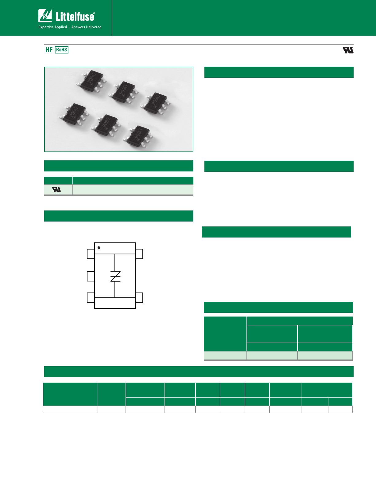
SIDACtor
1
2
5
43
(Tip)
NC
(Ring) (Ring)
(Tip)
Teccor® brand SIDACtor® DSL Protection Devices
P0080T023G5
®
Protection Thyristors
Description
This new P0080T023G5 is targeted for the tertiary or line
driver side protection position for VDSL2+ and ADSL2+
applications. This new low capacitance over voltage
protection does not require a bias voltage and is sufciently
robust for the chip-side position behind the coupling
transformer. This SOT23-5 solution, with its ow-through
design, minimizes PCB trace layout routing makes it
compatible with a variety of line drivers. Its low capacitance
makes it compatible with ADSL2 and VDSL2, and the
30MHz bandplan of VDSL2+.
Agency Approvals
Agency Agency File Number
E133083
Schematic Symbol
Features & Benefits
• Lower overshoot protection
than clamping
• SOT23-5 surface mount
package
• Low insertion loss
• Low capacitance
Protection solution to meet
• YD/T 950
• YD/T 993
• YD/T 1082
• GR 1089 Inter-building
• GR 1089 Intra-building
• IEC 61000-4-2
Surge Ratings
Series
10x1000 µs 8x20µs
• Bidirectional transient
voltage protection
• Robust surge rating
• RoHS compliant
• IEC 61000-4-5
• ITU K.20/21 Basic Level
• ITU K.20/21 Enhanced
Level
• TIA-968-A
• TIA-968-B
I
PP
Electrical Characteristics
Part Number Marking
P0080T023G5RP P08G 8 15 30 500 2.2 4 9.0 10
Notes:
- All measurement are made at an ambient temperature of 25°C Ipp applies to -40°C
throught +85°C temperature range.
- Ipp is repetitive surge rating and is guaranteed for the life of the product.
© 2012 Littelfuse, Inc.
Specifications are subject to change without notice.
Please refer to www.littelfuse.com for current information.
Amps min Amps min
18 50
V
DRM@IDRM
=5µA VS@250V/µs I
V min V max mA typ mA max A max V max pF typ pF Max
Revised: March 28, 2012
H
- SIDACtor devices are bidirectional. All electrical parameters and surge rating apply to
forward and reverse polarities.
- Specications are subject to change without notice.
1
355
I
S
I
T
VT@IT=2.2
Amps
Co@f=1MHz,2V
Page 2
®
SIDACtor
Protection Thyristors
Teccor® brand SIDACtor® DSL Protection Devices
Maximum Ratings
Parameter Name Symbol Test Conditions Value Units
10x 10 0 0µs 18 A
Lightning surge waveforms I
Operating Free Temperature Range T
Junction temperature T
Storage temperature T
Notes:
- The device also complies with IEC 61000-4-2 ESD ±15kV (air discharge), ±8 kV(cont act discharge) and IEC 610 00-4-4 EFT 40A(5/50nS)
- The device must initially be in thermal equilibrium with -40°C <T
- The lightning surge may be repeated after the device returns to its initial conditions.
pp
A
J
STG
<+150°C
J
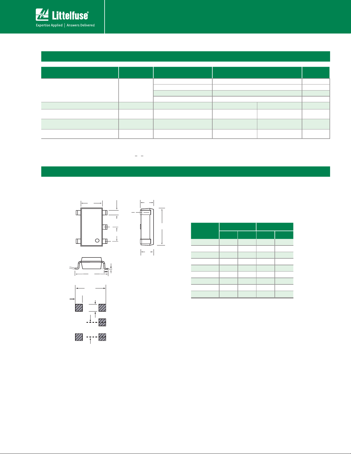
Mechanical dimensions, recommended layout dimensions
10x700µs/5x310µs 25 A
1.2x50µs/8x20µs 50 A
2x10µs 45 A
min max
-40 +85 °C
-40 +150 °C
-40 +150 °C
The epoxy meets UL 94V0 ratings.
A
D
A2
(and millimeters).
0.047(1.2)
E
B
0.037(0.95)
C
F
0.138(3.5)
0.024(0.60)
0.037(0.95)
A1
G
Dimension are in inches
Dimension
Inches Millimeters
Min Max Min Max
A 0.035 0.057 0.90 1.45
A1 0.000 0.004 0.00 0.10
A2 0.035 0.051 0.90 1.30
B 0.014 0.020 0.35 0.50
C 0.004 0.008 0.09 0.20
D 0.110 0.118 2.80 3.00
E 0.059 0.069 1.50 1.75
F 0.102 0.118 2.60 3.00
G 0.004 0.024 0.10 0.60
© 2012 Littelfuse, Inc.
Specifications are subject to change without notice.
Please refer to www.littelfuse.com for current information.
2
356
Revised: March 28, 2012
Page 3

®
-8
-40 -20 020406080100 120140 160
-6
-4
0
2
4
6
8
10
12
14
Junction Temperature (TJ) – °C
Percent of V
S
Change – %
25 °C
25°C
Case Temperature (TC) - ºC
2.0
1.8
1.6
1.4
1.2
1.0
0.8
0.6
0.4
-40 -20 020406080100 120140 160
Ratio of
I
H
I
H
(T
C
= 25ºC)
I
H
I
T
I
S
I
DRM
V
DRM
V
T
+
V
-V
+I
-I
V
S
0
2
4
6
8
10
12
14
6740123 58
Off-State Voltage (V)
Capacitance (pF)
3
SIDACtor
Protection Thyristors
Teccor® brand SIDACtor® DSL Protection Devices
Thermal Considerations
Package Symbol Parameter Value Unit
2
1
4
5
T
J
T
STG
R
0JA
Operating Junction Temperature Range -40 to +150 °C
Storage Temperature Range -40 to +150 °C
Thermal Resistance: Junction to Ambient 120 °C/W
Holding Current vs. Case Temperature
VS vs. Junction Temperature
V-I CharacteristicsCapacitance vs. Bias Voltage*
© 2012 Littelfuse, Inc.
Specifications are subject to change without notice.
Please refer to www.littelfuse.com for current information.
3
357
Revised: March 28, 2012
Page 4

P0080T023G5 Application example
®
SIDACtor
Protection Thyristors
Teccor® brand SIDACtor® DSL Protection Devices
The following schematics show alternate protection solutions
for a typical DSL interface that connects to outside wiring.
This surface mount SOT23-5 chip-side solution provides a
minimum footprint solution appropriate for high density card
designs. The P0080T023G5 will protect the interface from
lightning induced surges on the chip-side of the coupling
transformer. This tertiary protector may be preceded by lineside protection such as the TeleLink over-current protector
DSL driver chipset
Tip
Ring
1
2
NC
and the P0080T023G5 overvoltage protector. GDTs may also
be used on the line side of the coupling transformer. The
ow-through design of the SOT23-5 package is illustrated
below. If the inter winding capacitance of the transformer is
allowing some common mode events to get coupled across,
then the P0080T023G5 can be placed in a three chip mode,
as shown below for additional chip-side protection.
5
PCB Trace
43
PCB Trace
© 2012 Littelfuse, Inc.
Specifications are subject to change without notice.
Please refer to www.littelfuse.com for current information.
4
358
Revised: March 28, 2012
Page 5

®
Time
Temperature
T
P
T
L
T
S(max)
T
S(min)
25
t
P
t
L
t
S
time to peak temperature
(t 25ºC to peak)
Ramp-down
Ramp-up
Preheat
Critical Zone
T
L
to T
P
Figure 1
Time
Temperature
T
P
T
L
T
S(max)
T
S(min)
25
t
P
t
L
t
S
time to peak temperature
(t 25ºC to peak)
Ramp-down
Ramp-up
Preheat
Critical Zone
T
L
to T
P
Figure 1
Marking Code
P08G
Pin 1 indicator
SIDACtor
Protection Thyristors
Teccor® brand SIDACtor® DSL Protection Devices
Part Numbering
0080
T023 G RP
5
Packing Option
RP: Reel Pack
Number of pins
Surge Ipp rating
Product family
P=SIDACtor
Nominal Working voltage:
008=8V
Construction variable:
0=single chip
Package
T023=SOT23-5
P
Soldering Parameters
Reflow Condition
Pre Heat
- Temperature Min (T
- Temperature Max (T
- Time (Min to Max) (ts)
s(min)
s(max)
)
)
Average ramp up rate (Liquidus Temp (T
to peak)
to TL - Ramp-up Rate
T
S(max)
Reflow
- Temperature (TL) (Liquidus)
- Temperature (tL)
Peak Temp (TP) +260(+0/-5)°C
Time within 5°C of actual Peak Temp (t
Ramp-down Rate 6°C/sec. Max.
Time 25°C to Peak Temp (T
)
P
Do not exceed +260°C
Pb-Free assembly
(see Fig. 1)
+150°C
+200°C
60-180 secs.
)
L
3°C/sec. Max.
3°C/sec. Max.
+217°C
60-150 secs.
)
30 secs. Max.
p
8 min. Max.
Part Marking
Environmental Specifications
Physical Specifications
Terminal Material 100% Matte-Tin Plated
Solderability EIA J-STD-002, TEST A.
© 2012 Littelfuse, Inc.
Specifications are subject to change without notice.
Please refer to www.littelfuse.com for current information.
Mil-STD-883F, Method 1010.8 Condition
Temp Cycling
Bias Humidity
Pressure Cooker
High Temp Storage JESD 22-A103C Con B. 150°C, no bias 1000Hrs
HTRB
Thermal Shock
C-SAM
Wet Humidity
(Tin only)
5
359
Revised: March 28, 2012
C, -65°C to +150°C
168 Hrs, 85°C /60%RH+3IR-Reow,
260°C +5V, -0°C
JESD 22-A101-B 85°C , 85°CRH. 50V
168 Hrs, 85°C /60%RH+3IR-Reow,
260°C +5V, -0°C
JEDEC 22-A102C No Bias, 121°C,
100%RH 96Hrs/192Hrs.
168 Hrs, 85°C /60%RH+3IR-Reow,
260°C +5V, -0°C
JESD 22-108C
168 Hrs, 85°C /60%RH+3IR-Reow,
260°C +5V, -0°C
Mil-STD-883F, Method 1011.9 Condition
A, 0°C to 100°C
168 Hrs, 85°C /60%RH+3IR-Reow,
260°C +5V, -0°C
As per ow, JSTD-020C pre&post
preconditioning test.
NEMI standard: 60°C/93%RH
Page 6

Packing Options
HFOFSBM!JOGPSNBUJPO
2/!4111!QJFDFT!QFS!SFFM/
3/!PSEFS!JO!NVMUJQMFT!PG!GVMM!SFFMT!POMZ /
3/1nn
5/1nn
D
M
2/86nn
2/6nn
EJB/!IPMF
9nn
5/1nn
9/5nn
291nn
25/5nn
24nn
71nn
BDDFTT!IPMF
DPWFS!UBQF
VTFS!EJSFDUJPO!PG!GFFE
QJO!2
TPU34.6!)9nn!QPDLFU!QJUDI*
®
SIDACtor
Protection Thyristors
Teccor® brand SIDACtor® DSL Protection Devices
Package Type Description Quantity Added Suffix Min. Order Qty.
SOT023-5
SOT23-5
Tape & Reel Pack
3000 RP 3000 EIA-481-A
Tape and Reel Specification — SOT23-5
Industry Standard
© 2012 Littelfuse, Inc.
Specifications are subject to change without notice.
Please refer to www.littelfuse.com for current information.
Revised: March 28, 2012
360
6
 Loading...