

Littelfuse MPS User Manual
MPS MANUAL
MOTOR PROTECTION SYSTEM
Revision 6-F-022117
Copyright © 2017 by Littelfuse Startco
All rights reserved.
Document Number: PM-1130-EN

Factory default password is 1111
New Password
See Section 4.3.6.
Motor Identification

Page ii
MPS Motor Protection System Rev. 6-F-022117
. Table of Contents
TABLE OF CONTENTS
SECTION PAGE
List of Figures ....................................................................... iv
List of Tables ........................................................................ iv
Disclaimer .............................................................................. v
1 Introduction .......................................................... 1-1
1.1 General .................................................................... 1-1
1.2 MPS Features .......................................................... 1-1
1.2.1 Protection .................................................... 1-1
1.2.2 Control – Starting Methods ........................ 1-1
1.2.3 Metering ...................................................... 1-1
1.2.4 Data Logging .............................................. 1-1
1.2.5 Inputs and Outputs ...................................... 1-1
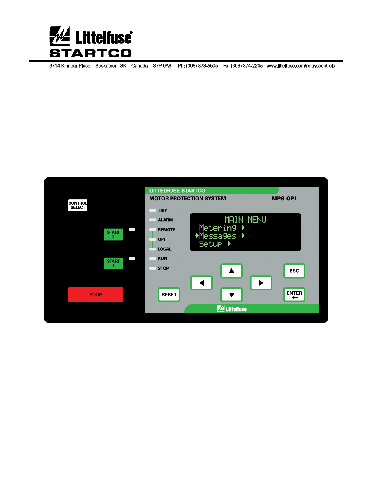
1.2.6 MPS-OPI Operator Interface ..................... 1-2
1.2.7 MPS-RTD Module ..................................... 1-2
1.2.8 MPS-DIF Differential Module ................... 1-2
1.2.9 Communications Interface ......................... 1-2
1.3 Ordering Information .............................................. 1-2
2 Installation ............................................................. 2-1
2.1 General .................................................................... 2-1
2.2 MPS-CTU Control Unit ......................................... 2-1
2.3 MPS-OPI Operator Interface .................................. 2-1
2.4 MPS-RTD Module ................................................. 2-1
2.5 MPS-DIF Differential Module ............................... 2-1
2.6 Earth-Fault CT’s ..................................................... 2-1
3 System Wiring ....................................................... 3-1
3.1 General .................................................................... 3-1
3.2 Wiring Connections ................................................ 3-1
3.2.1 MPS-CTU Connections ............................. 3-1
3.2.1.1 Supply Voltage .............................. 3-1
3.2.1.2 Current Inputs ................................ 3-1
3.2.1.3 Voltage Inputs ............................... 3-1
3.2.1.3.1 Direct Connection ........ 3-3
3.2.1.3.2 1-PT Connection .......... 3-3
3.2.1.3.3 2-PT Connection .......... 3-3
3.2.1.3.4 3-PT Connection .......... 3-3
3.2.1.4 Digital Inputs ................................. 3-3
3.2.1.4.1 DC Operation ............... 3-4
3.2.1.4.2 AC Operation ............... 3-4
3.2.1.4.3 Combined AC and
DC Operation ............................... 3-4
3.2.1.4.4 Tachometer
Input (HSI) ................................... 3-4
3.2.1.5 Analog Input (AN IN) ................... 3-4
3.2.1.6 Analog Output (AN OUT) ............ 3-4
3.2.1.7 PTC Input ...................................... 3-4
3.2.1.8 IRIG-B Input ................................. 3-4
3.2.1.9 I/O Module Communication ......... 3-4
3.2.1.10 RS-485 Network
Communications ......................................... 3-4
3.2.2 MPS-OPI Connections and
Address Selection ....................................... 3-4
3.2.3 MPS-RTD Connections and
Address Selection ....................................... 3-5
3.2.4 MPS-DIF Connections ............................... 3-5
3.2.4.1 Core Balance ................................. 3-5
TABLE OF CONTENTS
SECTION PAGE
3.2.4.2 MPS Summation ............................ 3-5
3.2.4.3 DIF Summation ............................. 3-5
3.2.5 Dielectric-Strength Testing ........................ 3-5
4 Operation and Setup ............................................ 4-1
4.1 General .................................................................... 4-1
4.2 MPS-CTU ............................................................... 4-1
4.2.1 LED Indication ........................................... 4-1
4.2.2 Reset Switch ................................................ 4-1
4.2.3 Phase-CT Inputs .......................................... 4-1
4.2.4 Earth-Fault-CT Input .................................. 4-2
4.2.5 Voltage Inputs ............................................. 4-2
4.2.6 Motor Data .................................................. 4-2
4.2.7 Output Relay Assignment .......................... 4-2
4.2.8 Digital Inputs 1 to 7 .................................... 4-3
4.2.9 Tachometer Input (HSI) ............................. 4-4
4.2.10 Analog Output ............................................. 4-4
4.2.11 Analog Input ............................................... 4-5
4.2.11.1 Metering only .............................. 4-5
4.2.11.2 Protection ..................................... 4-5
4.2.11.3 Synchronize to ASD .................... 4-5
4.2.11.4 Motor Speed ................................ 4-5
4.2.12 Starter .......................................................... 4-5
4.2.13 Protection .................................................... 4-5
4.2.14 Miscellaneous Configuration ..................... 4-5
4.2.15 Network Communications .......................... 4-5
4.3 MPS-OPI ................................................................. 4-5
4.3.1 General ........................................................ 4-5
4.3.2 Configuring the MPS-CTU for
OPI Operation ............................................. 4-5
4.3.3 Starter Control ............................................. 4-6
4.3.3.1 OPI Control .................................... 4-6
4.3.3.2 Local Control ................................. 4-6
4.3.3.3 Remote Control ............................. 4-6
4.3.4 Metering ...................................................... 4-7
4.3.5 Messages ..................................................... 4-7
4.3.5.1 Trip Reset ....................................... 4-7
4.3.5.2 Status .............................................. 4-7
4.3.5.3 Data Logging ................................. 4-9
4.3.5.4 Statistical Data ............................... 4-9
4.3.5.5 Emergency Thermal Reset ............ 4-9
4.3.6 Password Entry and Programming ............. 4-9
4.4 MPS-RTD ............................................................. 4-10
4.5 MPS-DIF ............................................................... 4-10
4.6 Waveform Capture ............................................... 4-10
5 Protective Functions ......................................... 5-1
5.1 General ............................................................... 5-1
5.2 Overload ............................................................. 5-1
5.2.1 Thermal Model ....................................... 5-1
5.2.2 Locked-Rotor Times ............................... 5-4
5.2.3 Emergency Thermal Reset ...................... 5-4
5.3 Overcurrent ........................................................ 5-4
5.4 Auxiliary Overcurrent ........................................ 5-5
5.5 Reduced Overcurrent ......................................... 5-5
5.6 Jam ..................................................................... 5-5
5.7 Earth Fault .......................................................... 5-5

Page iii
MPS Motor Protection System Rev. 6-F-022117
. Table of Contents
SECTION PAGE
5.8 Current Unbalance .............................................. 5-5
5.9 Phase Loss—Current .......................................... 5-6
5.10 Phase Reverse—Current ..................................... 5-6
5.11 Undercurrent ....................................................... 5-6
5.12 Overvoltage ........................................................ 5-6
5.13 Voltage Unbalance ............................................. 5-6
5.14 Phase Loss—Voltage ......................................... 5-6
5.15 Phase Reverse—Voltage .................................... 5-6
5.16 Undervoltage ...................................................... 5-7
5.17 Underpower ........................................................ 5-7
5.18 Reversepower ..................................................... 5-7
5.19 Power Factor—Quadrant 4 ................................. 5-7
5.20 Power Factor—Quadrant 3 ................................. 5-7
5.21 Underfrequency .................................................. 5-7
5.22 Overfrequency .................................................... 5-8
5.23 Starts per Hour/Time Between Starts ................. 5-8
5.24 Failure to Accelerate and Underspeed ................ 5-8
5.25 Differential Current Protection ........................... 5-9
5.26 PTC Temperature ............................................... 5-9
5.27 RTD Temperature .............................................. 5-9
5.28 Hot-Motor Compensation ................................ 5-10
5.29 Analog Input ..................................................... 5-10
5.29.1 Protection .............................................. 5-10
5.29.2 Synchronize to ASD ............................. 5-10
5.29.3 Motor Speed .......................................... 5-10
5.29.4 Metering Only ....................................... 5-10
6 Starter Functions .............................................. 6-1
6.1 General ............................................................... 6-1
6.2 Starter Timing Sequences ................................... 6-4
6.3 Full-Voltage Non-Reversing Starter .................. 6-7
6.4 Adjustable-Speed Drive ..................................... 6-7
6.5 Soft-Start Starter ................................................. 6-7
6.6 Full-Voltage Reversing Starter ........................... 6-8
6.7 Two-Speed Starter .............................................. 6-8
6.8 Reactor or Resistor Closed-Transition
Starter ............................................................... 6-10
6.9 Slip-Ring Starter ............................................... 6-10
6.10 Part-Winding and Double-Delta Starters ......... 6-11
6.11 Soft-Start-With-Bypass Starter ........................ 6-12
6.12 Reactor or Resistor Open-Transition Starter .... 6-12
6.13 Two-Winding Starter ........................................ 6-12
6.14 Wye-Delta Open-Transition Starter ................. 6-12
6.15 Autotransformer Closed-Transition Starter ...... 6-13
6.16 Wye-Delta Closed-Transition Starter ............... 6-13
7 Theory of Operation ......................................... 7-1
7.1 Signal-Processing Algorithms ............................ 7-1
7.2 Power Algorithm ................................................ 7-1
7.3 Operator Interface (MPS-OPI) ........................... 7-1
7.4 RTD Module (MPS-RTD) ................................. 7-1
7.5 Differential Module (MPS-DIF) ........................ 7-1
7.6 Firmware Diagnostics ........................................ 7-1
8 Communications ............................................... 8-1
8.1 Personal-Computer Interface .............................. 8-1
8.1.1 Firmware Upgrade .................................. 8-1
8.1.2 SE-Comm-RIS ........................................ 8-1
SECTION PAGE
8.2 Network Interface ............................................... 8-1
8.2.1 RS-485 Communications ........................ 8-1
8.2.2 DeviceNet Communications ................... 8-1
8.2.3 Ethernet Communications ....................... 8-1
8.2.4 Profibus Communications ....................... 8-1
9 Technical Specifications ................................... 9-1
9.1 Control Unit (MPS-CTU) .................................. 9-1
9.2 Operator Interface (MPS-OPI) ........................... 9-3
9.3 RTD Module (MPS-RTD) ................................. 9-3
9.4 Differential Module (MPS-DIF) ........................ 9-4
10 Warranty ........................................................... 9-5
Appendix A MPS-OPI Menu Map ............................ A-1
Appendix B MPS Set-Up Record .............................. B-1
Appendix C MPS Modbus Protocol .......................... C-1
Appendix D MPS A-B DF1 Protocol ......................... D-1
Appendix E Communications Database Table ......... E-1
Appendix F Register Formats .................................... F-1
Appendix G MPS Revision History .......................... G-1

Page iv
MPS Motor Protection System Rev. 6-F-022117
. Table of Contents
LIST OF FIGURES
FIGURE PAGE
1.1 Motor Protection System Block Diagram ............. 1-3
1.2 MPS Ordering Information .................................... 1-4
2.1 MPS-CTU Outline and Mounting Details ............. 2-2
2.1.1 MPS-CTU-XX-X1 Ring Terminal
Outline and Mounting Details ................................ 2-3
2.2 MPS-OPI Outline and Mounting Details ............... 2-4
2.3 MPS-CTU with OPI Outline and
Mounting Details .................................................... 2-5
2.3.1 MPS-CTU Ring Terminal with OPI Outline and
Mounting Details .................................................... 2-6
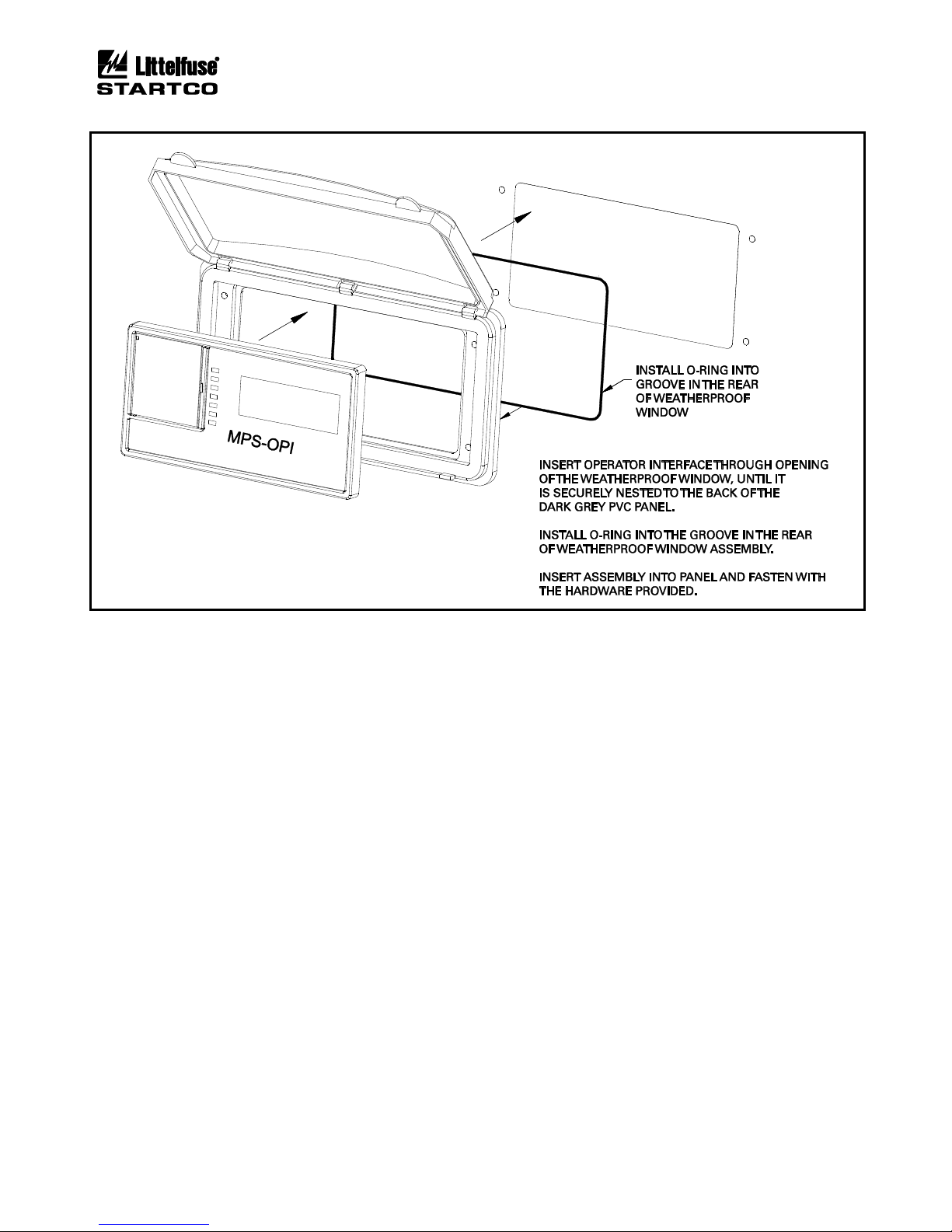
2.4 SE-IP65CVR-M Weatherproof Cover Outline .. 2-7
2.5 SE-IP65CVR-M Weatherproof Cover
Installation .......................................................... 2-8
2.6 MPS-RTD Outline and Mounting Details ............. 2-9
2.7 MPS-DIF Outline and Mounting Details ............. 2-10
2.8 EFCT-1 Outline and Mounting Details ............... 2-11
2.9 EFCT-2 Outline and Mounting Details ............... 2-12
2.10 EFCT-26 and SE-CS30-26 Outline and
Mounting Details .................................................. 2-13
2.11 SE-CS30-70 Outline and Mounting Details ........ 2-14
2.12 SE-CS30-4, -5, and -8 Outline and Mounting
Details ................................................................... 2-15
3.1 Residual Phase-CT Connection ............................. 3-1
3.2 Typical MPS Connection Diagram ........................ 3-2
3.3 Direct Connection ................................................... 3-3
3.4 1-PT Connection ..................................................... 3-3
3.5 2-PT Connection ..................................................... 3-3
3.6 3-PT Connection ..................................................... 3-3
3.7 Digital Tachometer Input (HSI) ............................. 3-4
3.8 Address Selection Switch Detail ............................ 3-5
3.9 Two Examples of I/O Module Connections .......... 3-6
3.10 MPS-RTD Connection Diagram ............................ 3-7
3.11 Core Balance Connection ....................................... 3-8
3.12 MPS Summation Connection ................................. 3-8
3.13 DIF Summation Connection .................................. 3-9
4.1 Menu Example ........................................................ 4-1
4.2 Menu Symbols ........................................................ 4-1
4.3 MPS-OPI Interface ................................................. 4-6
5.1 Class-20 Overload Curve ....................................... 5-3
5.2 Asymmetrical-Current Multipliers ......................... 5-5
5.3 Used I2t Bias Curve .............................................. 5-10
6.1 Typical 3-Wire Control .......................................... 6-3
6.2 Typical 2-Wire Control .......................................... 6-4
6.3 Starter Sequence 1 .................................................. 6-4
6.4 Starter Sequence 2 .................................................. 6-4
6.5 Starter Sequence 3 .................................................. 6-5
6.6 Starter Sequence 4 .................................................. 6-5
6.7 Starter Sequence 5 .................................................. 6-6
6.8 Starter Sequence 6 .................................................. 6-6
6.9 Full-Voltage Non-Reversing-Starter
Connection .............................................................. 6-7
6.10 Adjustable-Speed-Drive Connection ..................... 6-7
6.11 Soft-Start-Starter Connection ................................. 6-7
LIST OF FIGURES
FIGURE .............................................. PAGE
6.12 Full-Voltage-Reversing-Starter Connection .......... 6-8
6.13 Two-Speed Two-Winding-Starter Connection ...... 6-8
6.14 Two-Speed Constant- and Variable-Torque-
Starter Connections ................................................. 6-9
6.15 Two-Speed Constant-Horsepower-Starter
Connection ............................................................... 6-9
6.16 Reactor or Resistor-Starter Connection ................ 6-10
6.17 Slip-Ring-Starter Connection ................................ 6-10
6.18 Part-Winding and Double-Delta-Starter
Connections ........................................................... 6-11
6.19 Soft-Start-With-Bypass-Starter Connection ......... 6-12
6.20 Two-Winding-Starter Connection ........................ 6-13
6.21 Wye-Delta Open-Transition-Starter
Connection ............................................................. 6-14
6.22 Autotransformer Closed-Transition-Starter
Connection ............................................................. 6-14
6.23 Wye-Delta Closed-Transition-Starter
Connection ............................................................. 6-15
LIST OF TABLES
TABLE PAGE
3.1 MPS-OPI Address Selection ................................... 3-4
3.2 MPS-RTD Address Selection ................................. 3-5
4.1 Output-Relay Functions .......................................... 4-2
4.2 Digital-Input Functions ........................................... 4-3
4.3 Analog-Output Parameters ...................................... 4-4
4.4 Metering Display ..................................................... 4-8
4.5 Status Messages ....................................................... 4-8
5.1 Trip Time ................................................................. 5-4
5.2 Fault Duration Required for Trip ............................ 5-4
6.1 Start-Source Summary ............................................ 6-1
6.2 Starter Summary ...................................................... 6-3

Page v
MPS Motor Protection System Rev. 6-F-022117
. Table of Contents
DISCLAIMER
Specifications are subject to change without notice.
Littelfuse Startco is not liable for contingent or
consequential damages, or for expenses sustained as a result
of incorrect application, incorrect adjustment, or a
malfunction.

Page 1-1
MPS Motor Protection System Rev. 6-F-022117
Introduction
1. INTRODUCTION
1.1 GENERAL
The Littelfuse Startco Motor Protection System (MPS)
is a modular system with integrated protection, control,
metering, and data-logging functions. The Control Unit
(MPS-CTU) is the core module. It can operate as a standalone unit or with the Operator Interface (MPS-OPI),
RTD Modules (MPS-RTD), and Differential Module
(MPS-DIF). The CTU can be programmed using the OPI
or the communications network. Programmable inputs
and outputs provide a flexible hardware platform and
custom software can be easily loaded from a PC to the
CTU’s flash memory. The MPS block diagram is shown
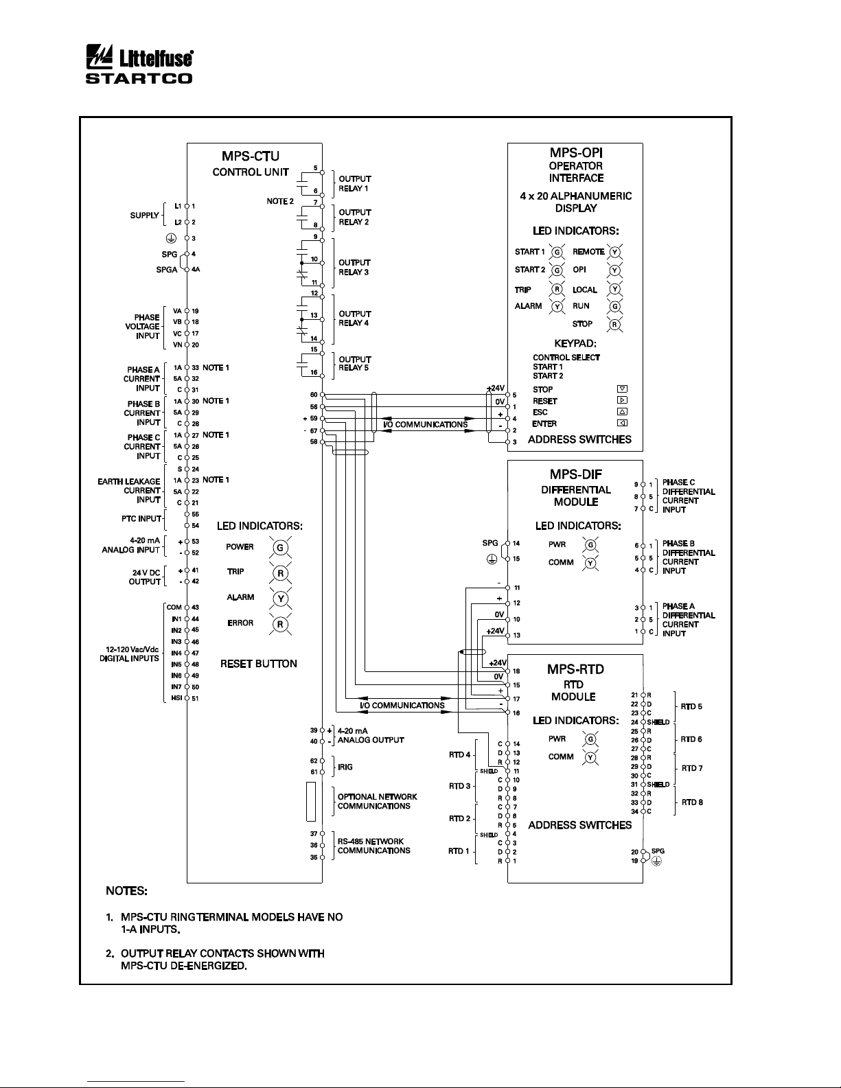
in Fig. 1.1.
1.2 MPS FEATURES
1.2.1 PROTECTION
• Overload (49, 51)
• Overcurrent (50, 51)
• Earth fault (50G/N, 51G/N)
• Unbalance (voltage and current) (46, 47)
• Phase loss (voltage and current) (46, 47)
• Phase reverse (voltage and current) (46, 47)
• Jam
• Undercurrent (37)
• Failure to accelerate
• Underspeed (14)
• Overvoltage (59)
• Undervoltage (27)
• Underpower (37)
• Reversepower (32)
• Power factor (55)
• Overfrequency (81)
• Underfrequency (81)
• PTC overtemperature (49)
• RTD temperature (38, 49)
• Starts per Hour (66)
• Differential (87)
1.2.2 CONTROL—STARTING METHODS
(1)
• Non-reversing
• Reversing
• Soft start
• Soft start with bypass
• Adjustable-speed drive
• Two speed
• Wye-delta (open or closed transition)
• Reactor (open or closed transition)
• Resistor (open or closed transition)
• Autotransformer
• Part winding
• Slip ring
• Two winding
• Double delta
(1)
Only three CT’s required for all starting methods.
1.2.3 METERING
• Line currents
• Current unbalance
• Positive-sequence current
• Negative-sequence current
• Earth-leakage current
• Differential currents
• Line-to-line voltages
• Line frequency
• Voltage unbalance
• Positive-sequence voltage
• Negative-sequence voltage
• Power
§ Apparent, Reactive, Real, and Power factor
• Energy
§ kWh, kVAh, and kVARh
• Used thermal capacity
• Thermal trend
• Motor speed
• RTD temperatures
• Analog input and output
1.2.4 DATA LOGGING
• Sixty-four records
§ Date and time of event
§ Event type
§ Line currents
§ Current unbalance
§ Earth-leakage current
§ Differential currents
§ Line-to-line voltages
§ Voltage unbalance
§ Thermal capacity
§ Thermal capacity used during starts
§ Start time
§ Analog-input value
§ Frequency
§ Power (P, S, Q, PF)
§ RTD temperatures
§ Trip counters
§ Running hours
§ Waveform Capture
§ 5 seconds of pre-trip waveform data
§ 16 samples per cycle
§ COMTRADE and CSV file generation
1.2.5 INPUTS AND OUTPUTS
• Three ac-current inputs
• Three ac-voltage inputs
• Earth-leakage-current input
• Seven programmable digital (ac/dc) inputs
• 24-Vdc source for digital inputs
• Tachometer (high-speed pulse) input
• 4-20-mA analog input
• 4-20-mA analog output
• PTC thermistor temperature input

Page 1-2
MPS Motor Protection System Rev. 6-F-022117
Introduction
• Up to twenty-four RTD inputs
• Five programmable output relays
• Network communications
• IRIG-B time-code input
1.2.6 MPS-OPI OPERATOR INTERFACE
• 4 x 20 vacuum-fluorescent display
• Starter-control keys
• Display-control and programming keys
• LED status indication
• Remote operation up to 1.2 km (4,000’)
• Powered by MPS-CTU
1.2.7 MPS-RTD MODULE
• Eight inputs per module
• Individually selectable RTD types
• RTD Voting
• Solid-state multiplexing
• Up to three modules per system
• Remote operation up to 1.2 km (4,000’)
• Powered by MPS-CTU
1.2.8 MPS-DIF DIFFERENTIAL MODULE
• 3-CT core-balance connection
• 6-CT summation connection
• Remote operation up to 1.2 km (4,000’)
• Powered by MPS-CTU
1.2.9 COMMUNICATIONS INTERFACE
The standard network communication interface is an
RS-485 port with Modbus® RTU and A-B® DF1 protocol
support. In addition to the standard interface, network
communication options include DeviceNet™, Profibus®,
Modbus® TCP, and Ethernet/IP.
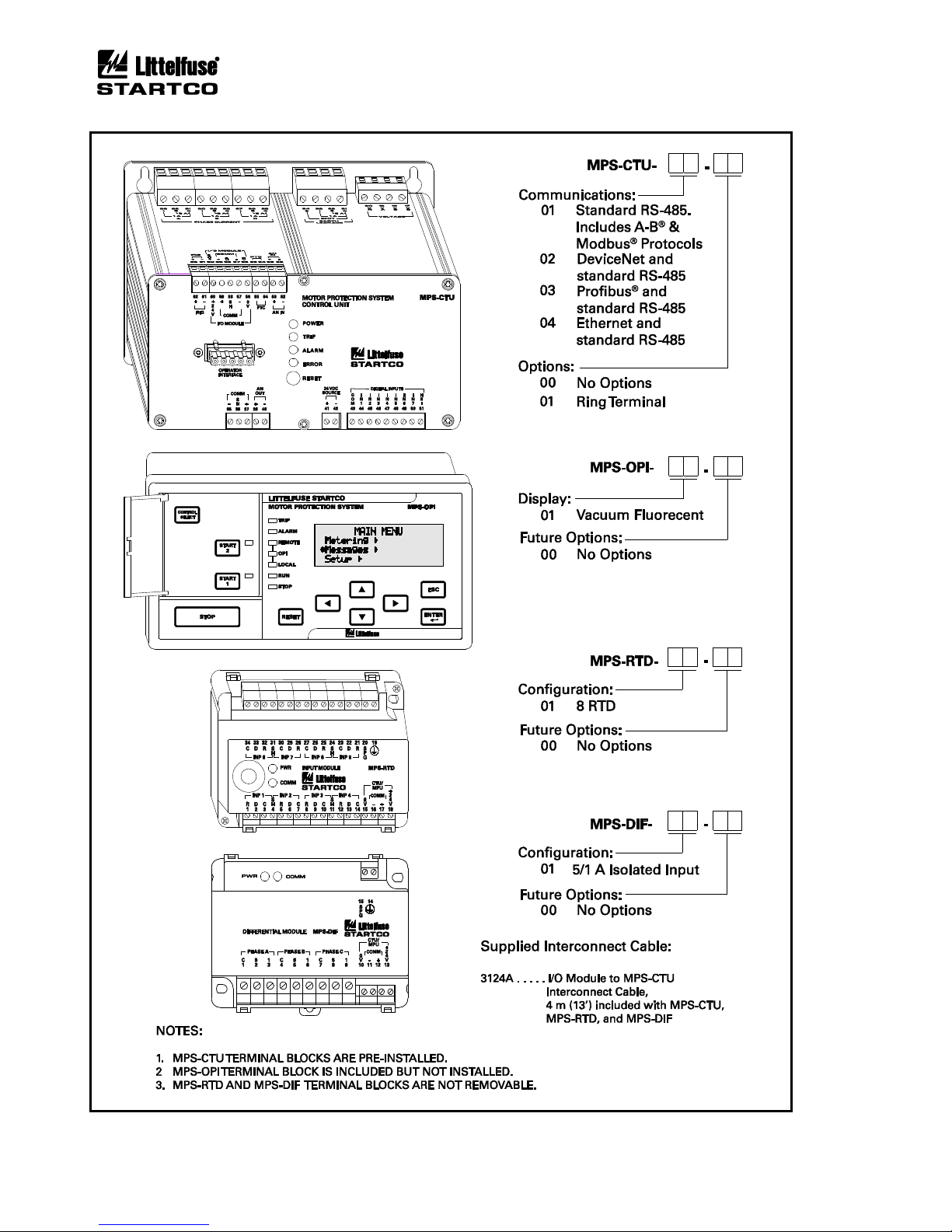
1.3 ORDERING INFORMATION
See Fig. 1.2 for MPS-CTU, MPS-OPI, MPS-RTD, and
MPS-DIF model numbers.
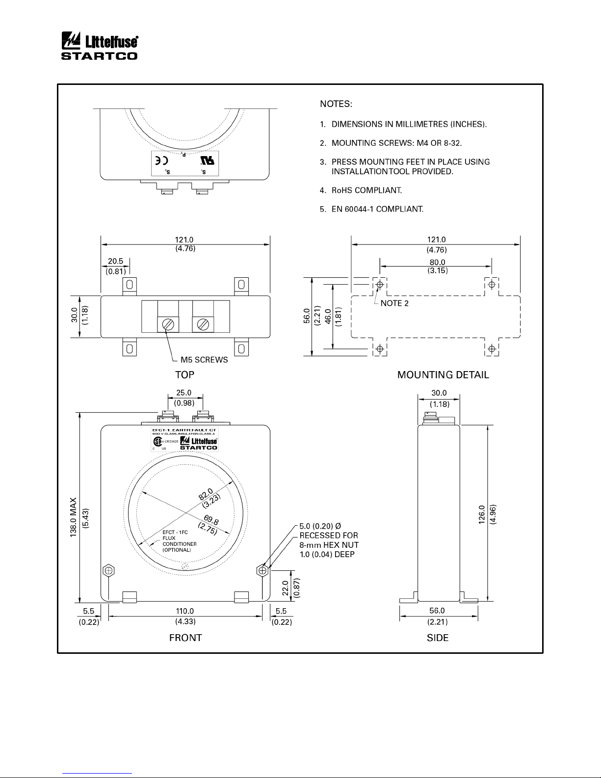
Earth-Fault Current Sensors:
EFCT-1 ......................... Earth-Fault CT,
5-A-primary rating,
82 mm (3.2”) window
EFCT-1FC ..................... Flux Conditioner for EFCT-1,
70 mm (2.7”) window
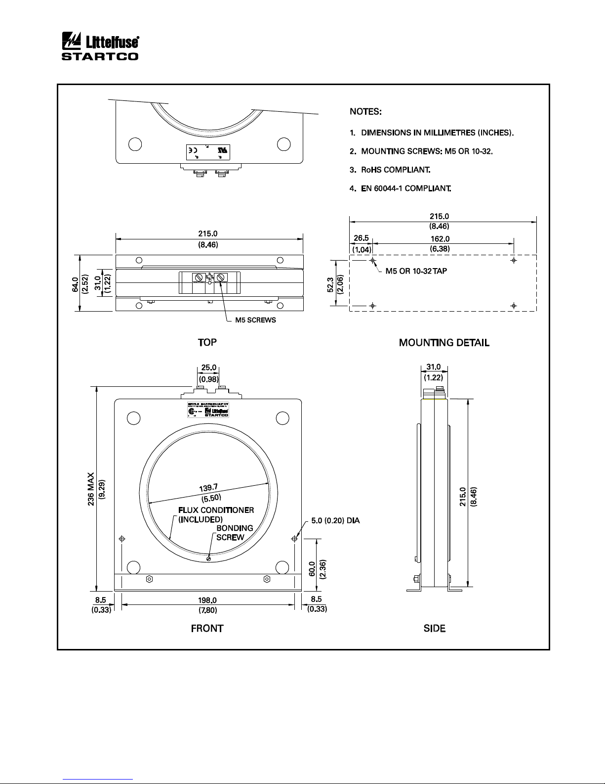
EFCT-2 ......................... Earth-Fault CT with
Flux Conditioner,
5-A-primary rating,
139 mm (5.5”) window
EFCT-26 ....................... Earth-Fault CT,
5-A-primary rating,
26 mm (1”) window
(All EFCT’s include 6 m (19.5’) of 22 AWG (0.33 mm2)
shielded cable.)
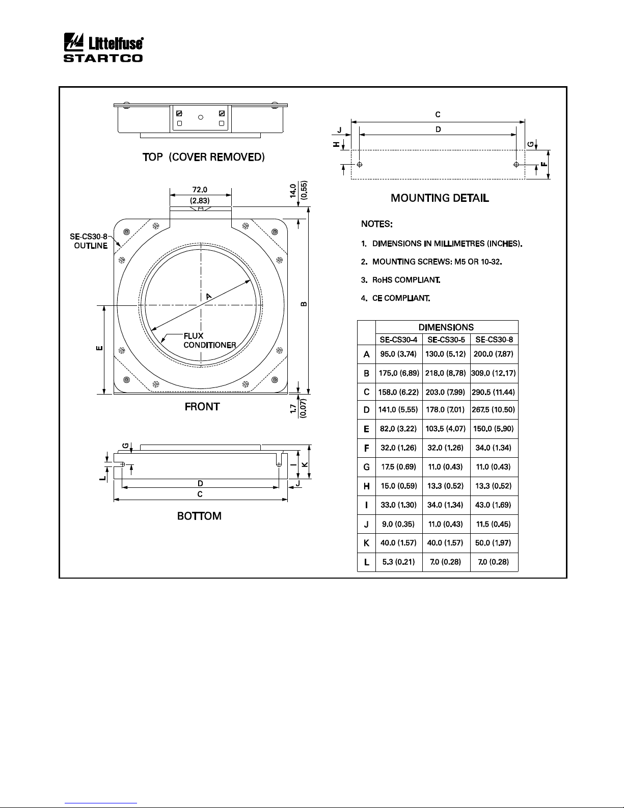
SE-CS30-4 ............................. Current Sensor,
30-A-primary rating,
c/w Flux Conditioner,
95.0 mm (3.7”) window
SE-CS30-5 ............................. Current Sensor,
30-A-primary rating,
c/w Flux Conditioner,
130.0 mm (5.1”) window
SE-CS30-8 ............................. Current Sensor
30-A-primary rating,
c/w Flux Conditioner,
200.0 mm (7.9”) window
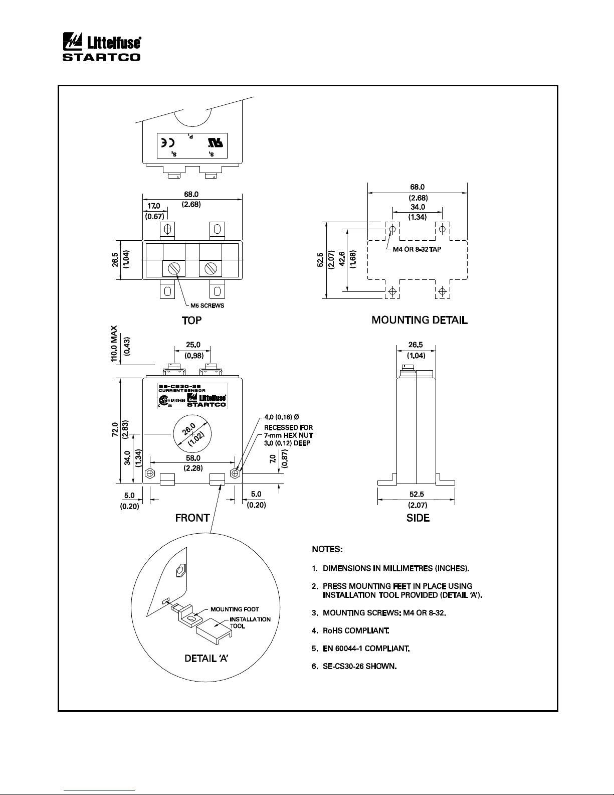
SE-CS30-26 ......................... Current Sensor,
30-A-primary rating,
26 mm (1.0”) window
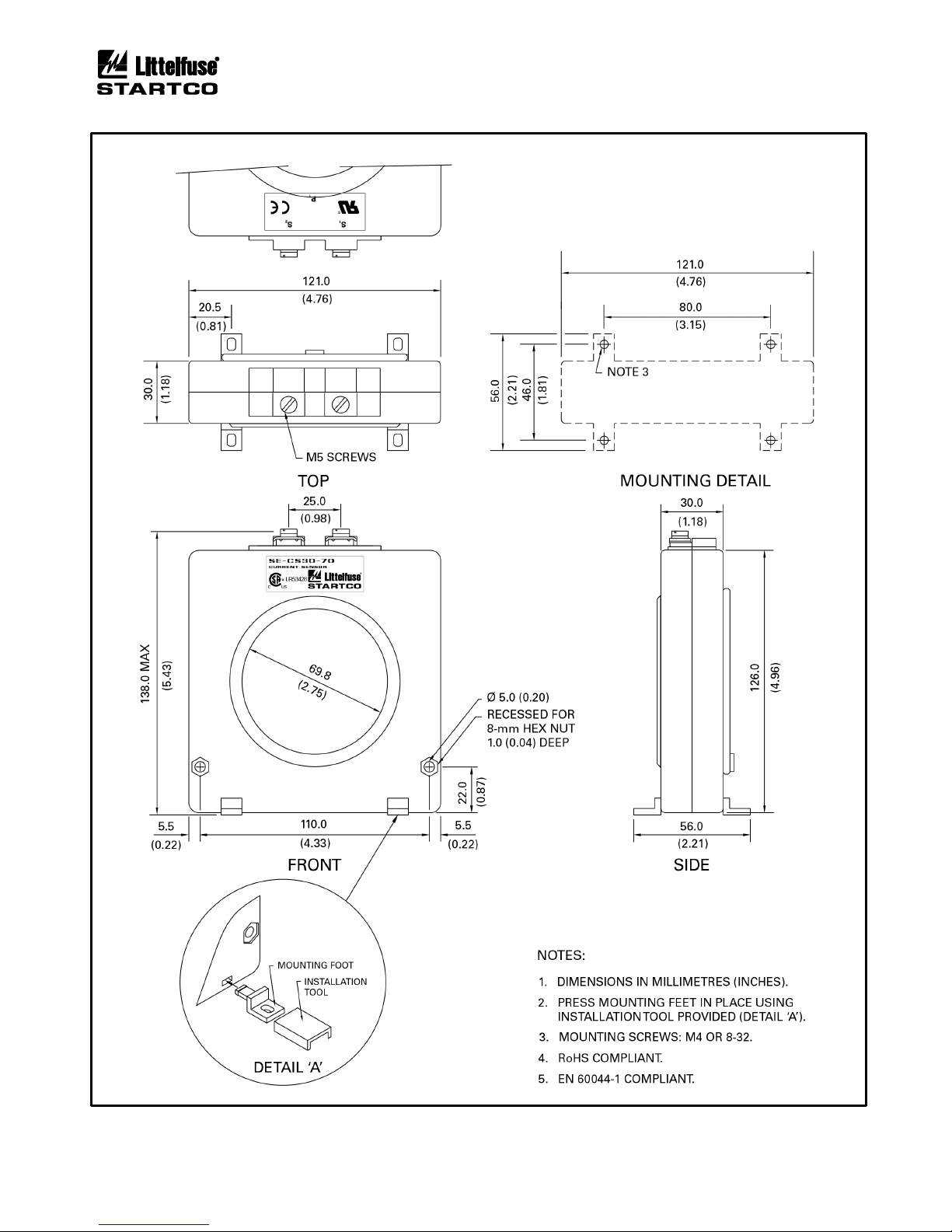
SE-CS30-70 ......................... Current Sensor,
30-A-primary rating,
70 mm (2.7”) window
Phase CT’s ............................... Protection-Class CT’s,
Contact factory
Accessories:
SE-IP65CVR-M ................... Hinged Transparent OPI
Cover
SE-485-PP ............................ Port-Powered Serial
Converter
SE-485-DIN ......................... Serial Converter,
Industrial, 24 Vdc
Software:
SE-Comm-RIS ..................... PC Communication
Software
(1)
SE-Flash ............................... Firmware Upgrade
Software
(1)
(1)
Available at www.littelfuse.com/relayscontrols.
Page 1-3
MPS Motor Protection System Rev. 6-F-022117
Introduction
FIGURE 1.1 Motor Protection System Block Diagram.
Page 1-4
MPS Motor Protection System Rev. 6-F-022117
Introduction
FIGURE 1.2 MPS Ordering Information.

Page 2-1
MPS Motor Protection System Rev. 6-F-022117
Installation
2. INSTALLATION
2.1 GENERAL
A basic Motor Protection System (MPS) consists of an
MPS-CTU and three customer-supplied current
transformers (CT's) for measuring phase current. For
core-balance earth-fault detection, a 1-A, 5-A, EFCT-1, or
EFCT-2 CT is required. For the optional Ring Terminal
MPS-CTU, the 1-A connection is not available. The
residual phase-CT connection can also be used for earthfault detection. Voltage inputs do not require potential
transformers (PT’s) for system voltages up to 600 Vac.
For RTD-temperature measurement, up to three
MPS-RTD modules can be connected to the MPS-CTU.
For differential protection, an MPS-DIF module can be
connected to the MPS-CTU. The MPS-OPI provides an
operator interface for the MPS.
The MPS power-factor-corrected switch-mode power
supply is rated 65 to 265 Vac and 80 to 275 Vdc.
All modules can be mounted in any orientation.
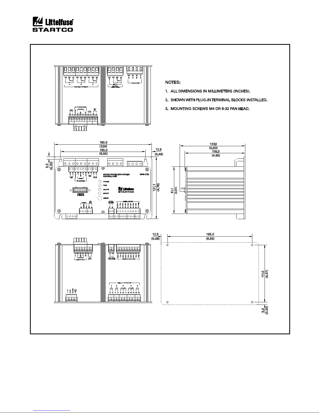
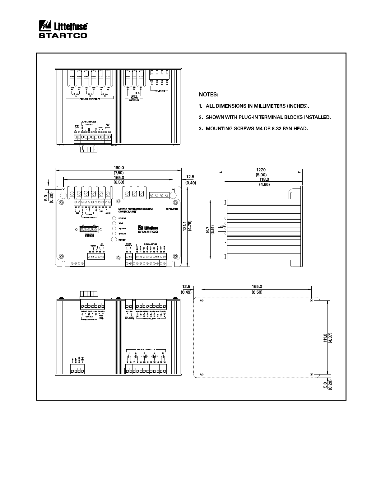
2.2 MPS-CTU CONTROL UNIT
The Control Unit is configured for surface mounting.
Outline and mounting details for the MPS-CTU are
shown in Figs. 2.1 and 2.1.1.
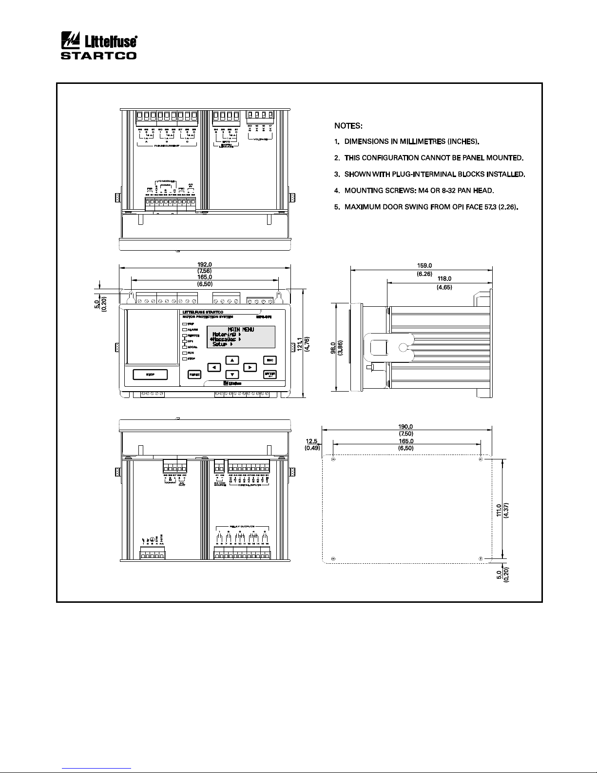
2.3 MPS-OPI OPERATOR INTERFACE
Outline and mounting details for the MPS-OPI are
shown in Fig. 2.2. It is certified for use in Class I, Zone 2
and Class I, Division 2 hazardous locations.
The Operator Interface is configured for panel
mounting or it can be mounted on the MPS-CTU as
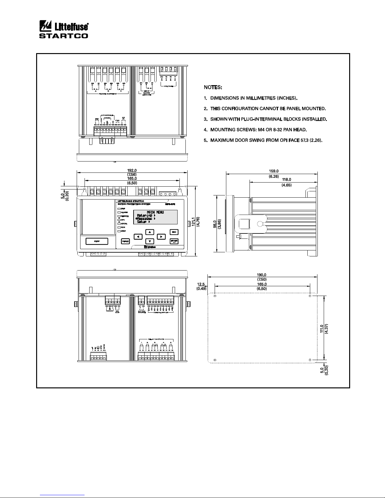
shown in Fig. 2.3. The Operator Interface can also be
mounted on the MPS-CTU ring terminal as shown in
Fig. 2.3.1 (surface mount only).
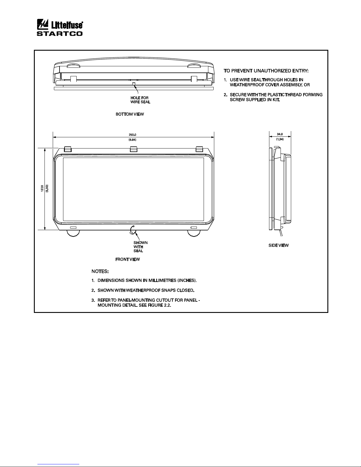
If an optional SE-IP65CVR-M is used, follow the
included installation instructions. See Figs. 2.4 and 2.5.
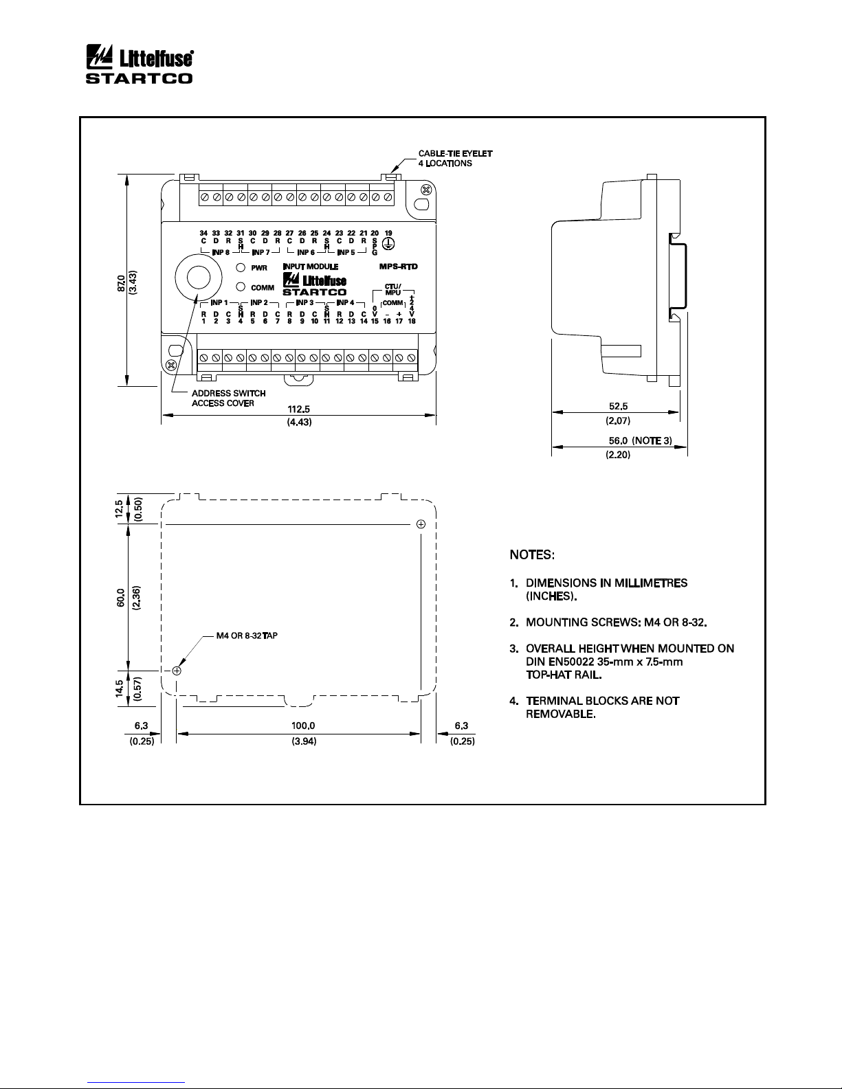
2.4 MPS-RTD MODULE
Outline and mounting details for the MPS-RTD are
shown in Fig. 2.6. The MPS-RTD will fit inside most
motor RTD-termination junction boxes and it is certified
for use in Class I, Zone 2 and Class I, Division 2
hazardous locations. The MPS-RTD can be surface or
DIN-rail mounted.
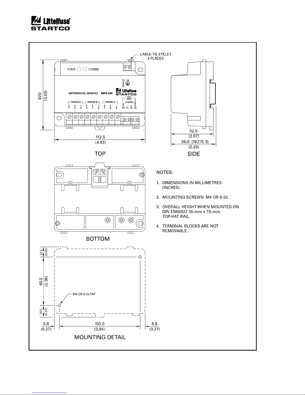
2.5 MPS-DIF DIFFERENTIAL MODULE
Outline and mounting details for the MPS-DIF are
shown in Fig 2.7. The MPS-DIF can be surface or DINrail mounted.
2.6 EARTH-FAULT CT’S
Outline and mounting details for the EFCT-1, EFCT-2,
EFCT-26, and SE-CS30 series are shown in Figs. 2.8, 2.9,
2.10, 2.11, and 2.12.
Page 2-2
MPS Motor Protection System Rev. 6-F-022117
Installation
FIGURE 2.1 MPS-CTU Outline and Mounting Details.
Page 2-3
MPS Motor Protection System Rev. 6-F-022117
Installation
FIGURE 2.1.1 MPS-CTU-XX-X1 Ring Terminal Outline and Mounting Details.

Page 2-4
MPS Motor Protection System Rev. 6-F-022117
Installation
FIGURE 2.2 MPS-OPI Outline and Mounting Details.
Page 2-5
MPS Motor Protection System Rev. 6-F-022117
Installation
FIGURE 2.3 MPS-CTU with OPI Outline and Mounting Details.
Page 2-6
MPS Motor Protection System Rev. 6-F-022117
Installation
FIGURE 2.3.1 MPS-CTU Ring Terminal with OPI Outline and Mounting Details.
Page 2-7
MPS Motor Protection System Rev. 6-F-022117
Installation
FIGURE 2.4 SE-IP65CVR-M Weatherproof Cover Outline.
Page 2-8
MPS Motor Protection System Rev. 6-F-022117
Installation
FIGURE 2.5 SE-IP65CVR-M Weatherproof Cover Installation.
Page 2-9
MPS Motor Protection System Rev. 6-F-022117
Installation
FIGURE 2.6 MPS-RTD Outline and Mounting Details.
Page 2-10
MPS Motor Protection System Rev. 6-F-022117
Installation
FIGURE 2.7 MPS-DIF Outline and Mounting Details.
Page 2-11
MPS Motor Protection System Rev. 6-F-022117
Installation
FIGURE 2.8 EFCT-1 Outline and Mounting Details.
Page 2-12
MPS Motor Protection System Rev. 6-F-022117
Installation
FIGURE 2.9 EFCT-2 Outline and Mounting Details.
Page 2-13
MPS Motor Protection System Rev. 6-F-022117
Installation
FIGURE 2.10 EFCT-26 and SE-CS30-26 Outline and Mounting Details.
Page 2-14
MPS Motor Protection System Rev. 6-F-022117
Installation
FIGURE 2.11 SE-CS30-70 Outline and Mounting Details.
Page 2-15
MPS Motor Protection System Rev. 6-F-022117
Installation
FIGURE 2.12 SE-CS30-4, -5, and -8 Outline and Mounting Details.

Page 2-16
MPS Motor Protection System Rev. 6-F-022117
Installation
This page intentionally left blank.
Page 3-1
MPS Motor Protection System Rev. 6-F-022117
System Wiring
3. SYSTEM WIRING
3.1 GENERAL
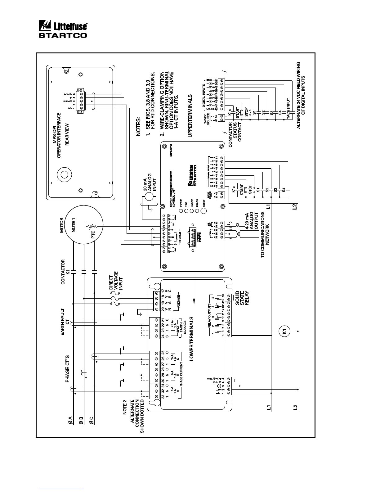
A typical connection diagram is shown in Fig. 3.2. The
MPS-CTU provides the 24-Vdc supply for the peripheral
modules and it communicates with them using an RS-485
interface. The total length of the I/O communication
system must be less than 1.2 km (4,000’). I/O
communications addressing supports up to three modules
of each type; however, the power supply in the MPS-CTU
will not support more than three I/O modules. An
external 24-Vdc power supply is required if more than
three modules are used.
The MPS-CTU voltage inputs can be directly
connected to a system with line-to-line voltages up to
600 Vac. PT's are required for system voltages higher
than 600 Vac. Input resistance of the voltage inputs is
3.4 MΩ.
NOTE: The current and voltage inputs must be phase
sequenced A-B-C with correct polarity observed.
START1, START2, and STOP starter-control
commands can be issued through the digital inputs, the
network interface, or the MPS-OPI. Start, stop, and
interlock contacts can be wired to any of the
programmable digital inputs. The five programmable
output relays can be used for starting control, protection,
and interlock functions. Relay 5 is a solid-state, low-level
output relay not recommended for starter control. See
Section 9 for relay ratings.
NOTE: The default configuration has no assignments for
digital inputs and relay outputs.
3.2 WIRING CONNECTIONS
3.2.1 MPS-CTU CONNECTIONS
The MPS-CTU CT-input terminal blocks accept 22 to
10 AWG (0.3 to 4.0 mm2) conductors. The remaining
MPS-CTU clamping blocks accept 24 to 12 AWG
(0.2 to 2.5 mm2) conductors. Terminal blocks unplug to
allow the MPS-CTU to be easily replaced.
The MPS-CTU Ring Terminal CT-input terminal block
accept a maximum ring width of 8 mm (0.315”). These
terminal blocks cannot be unplugged.
3.2.1.1 SUPPLY VOLTAGE
Derive supply voltage from the line side of the motor
controller or from an independent source. Connect supply
voltage to terminals 1 and 2 (L1 and L2) as shown in
Fig. 3.2. In 120-Vac systems, L2 is usually designated as
the neutral conductor. For direct-current power supplies,
use L1 for the positive terminal and L2 as the negative
terminal. Earth terminal 3 ( ).
Internal surge-protection devices are connected to
terminals 4 (SPG) and 4A (SPGA) to allow dielectricstrength testing. Terminals 4 and 4A must be connected
except during dielectric-strength testing.
The 24-Vdc I/O module supply (terminals 56 and 60)
can support three I/O modules. An external 24-Vdc
supply is required if more than three modules are used.
3.2.1.2 CURRENT INPUTS
The MPS-CTU uses 1-A or 5-A CT’s for phase-current
measurement. The MPS-CTU Ring Terminal uses 5-A
CT’s for phase-current measurement. To maintain
specified accuracy, phase CT’s should be protection class
and selected with a primary rating between 100 and 300%
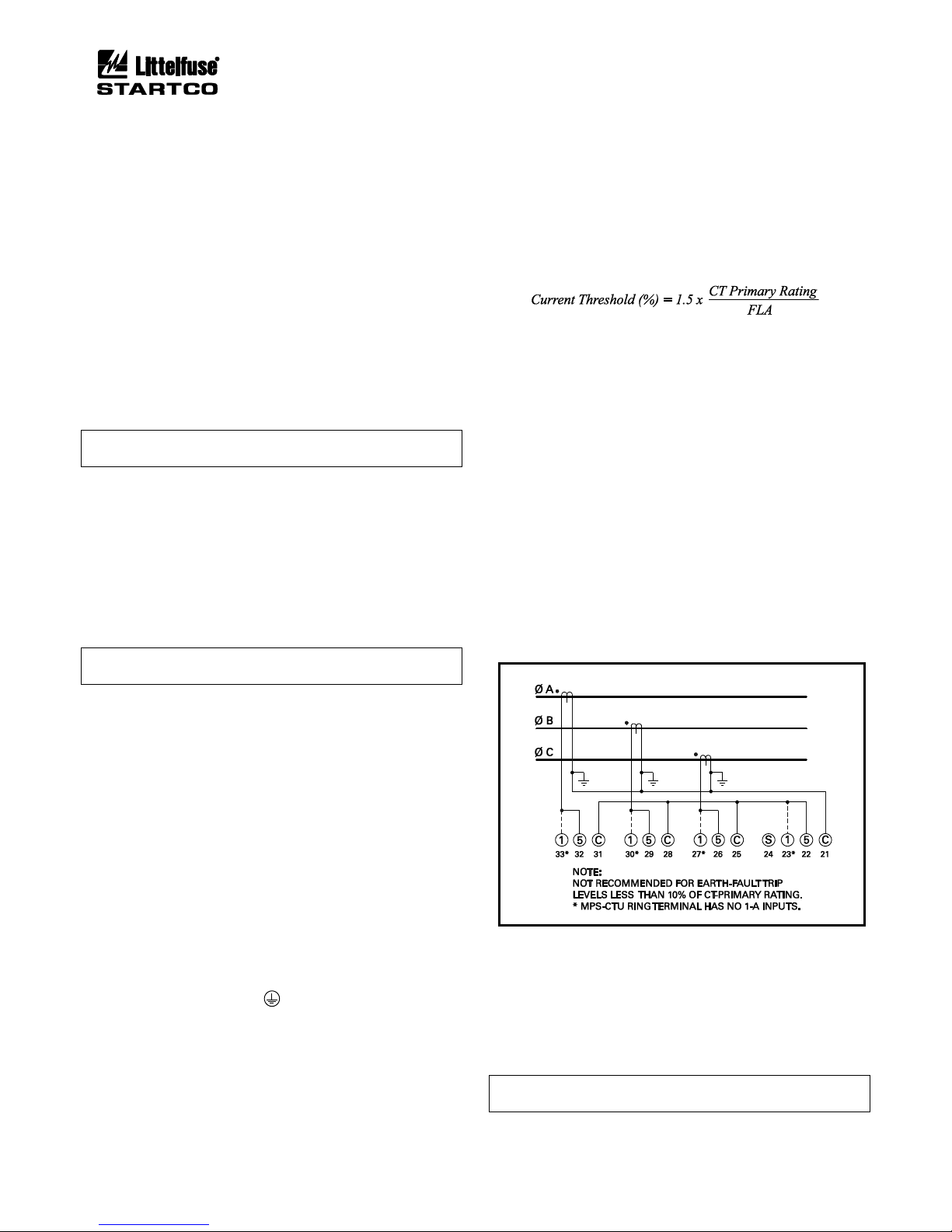
of motor full-load current (FLA). Current threshold is a
function of full-load current and CT-primary rating as
defined by the following formula.
The Current Threshold is also used to determine when
the motor is in Run mode. Several protective functions
are only enabled when in Run mode. See Section 5.1 for
a description of Run mode.
For synchronous-motor applications, the CT-primary
rating should be selected such that the current threshold is
less than the idle current, typically less than 5%. All CT
inputs can withstand a common-mode voltage of 120 Vac
so that the MPS-CTU can be connected in series with
other CT loads. The connection diagram in Fig. 3.2
shows a typical connection where the MPS-CTU is the
only device connected to the phase CT's. The MPS-CTU
requires the phase sequence to be A-B-C with correct
polarity.
The Ip Threshold sets the current level where unbalance
protection becomes active. See Section 5.8.
A 1-A, 5-A, or sensitive CT is used for core-balance
earth-leakage measurement. The MPS-CTU Ring
Terminal has no 1-A input. See Fig. 3.1 for the phase-CT
residual connection for earth-fault detection.
FIGURE 3.1 Residual Phase-CT Connection.
3.2.1.3 VOLTAGE INPUTS
For all input-voltage connections, the MPS-CTU
requires the phase sequence to be A-B-C with correct
polarity.
If voltage inputs are not used, connect VA, VB, and
VC to VN.
NOTE: A voltage input is required for line-frequency
metering.
Page 3-2
MPS Motor Protection System Rev. 6-F-022117
System Wiring
FIGURE 3.2 Typical MPS Connection Diagram.
Page 3-3
MPS Motor Protection System Rev. 6-F-022117
System Wiring
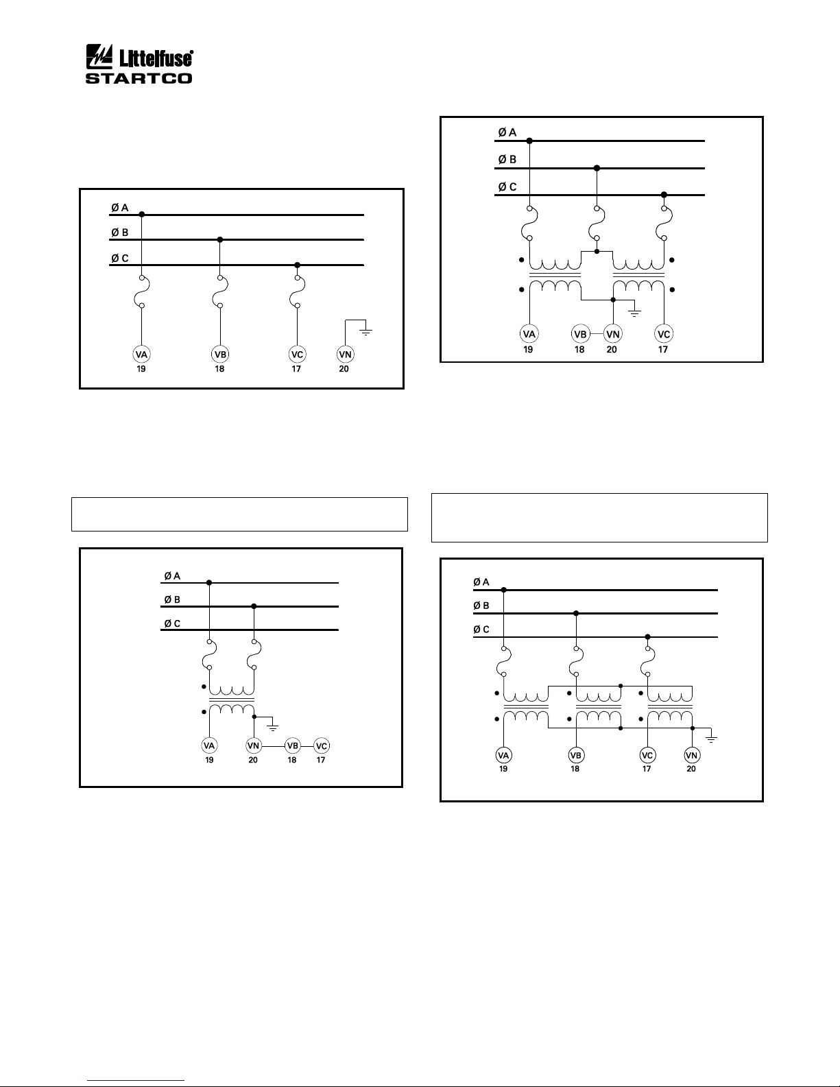
3.2.1.3.1 DIRECT CONNECTION
PT's are not required for system voltages up to 600 Vac
line-to-line. Connect the voltage inputs as shown in
Figs. 3.2 and 3.3.
FIGURE 3.3 Direct Connection.
3.2.1.3.2 1-PT CONNECTION
The 1-PT connection is shown in Fig. 3.4. Connect the
PT between phase A and phase B. The PT-secondary
voltage must be less than 350 Vac.
NOTE: The 1-PT connection does not allow detection of
voltage unbalance.
FIGURE 3.4 1-PT Connection.
3.2.1.3.3 2-PT CONNECTION
The 2-PT connection is shown in Fig. 3.5. The PTsecondary voltages must be less than 350 Vac. Connect
the PT secondaries in open delta.
FIGURE 3.5 2-PT Connection.
3.2.1.3.4 3-PT CONNECTION
The 3-PT connection is shown in Fig. 3.6. The PTsecondary voltages must be less than 350 Vac. Since the
MPS-CTU measures line-to-line voltage, there is no
advantage in using a 3-PT connection over a 2-PT
connection.
NOTE: This connection relies on PT primarymagnetization current for voltage balance. Do not
connect any other secondary loads.
FIGURE 3.6 3-PT Connection.
3.2.1.4 DIGITAL INPUTS
Digital inputs 1 to 8 (terminals 44 to 51) are referenced
to COM (terminal 43). These inputs are isolated from all
other terminals and operate over a 12 to 120 Vac/Vdc
range. Inputs 1 to 7 have programmable functions. See
Table 4.2. Input 8 is a high-speed input (HSI) for a
tachometer sensor.
Page 3-4
MPS Motor Protection System Rev. 6-F-022117
System Wiring
3.2.1.4.1 DC OPERATION
Supply voltage for dc-input operation can be obtained
from the 24-Vdc source (terminals 41 and 42), or it can be
obtained from an external 12- to 120-Vdc supply.
The internal source is current limited at 100 mA and is
referenced to the analog output (terminal 40) and the I/O
Supply (terminal 56). Connect the “−” terminal of the dc
source to COM and connect field inputs between “+” and
the digital-input terminals.
3.2.1.4.2 AC OPERATION
Inputs operate over a 12- to 120-Vac range. Connect
the ac neutral to COM and connect field inputs between
line and the digital inputs.
3.2.1.4.3 COMBINED AC AND DC OPERATION
If both ac and dc inputs are used, connect both the acsupply common and dc-supply “−” to COM.
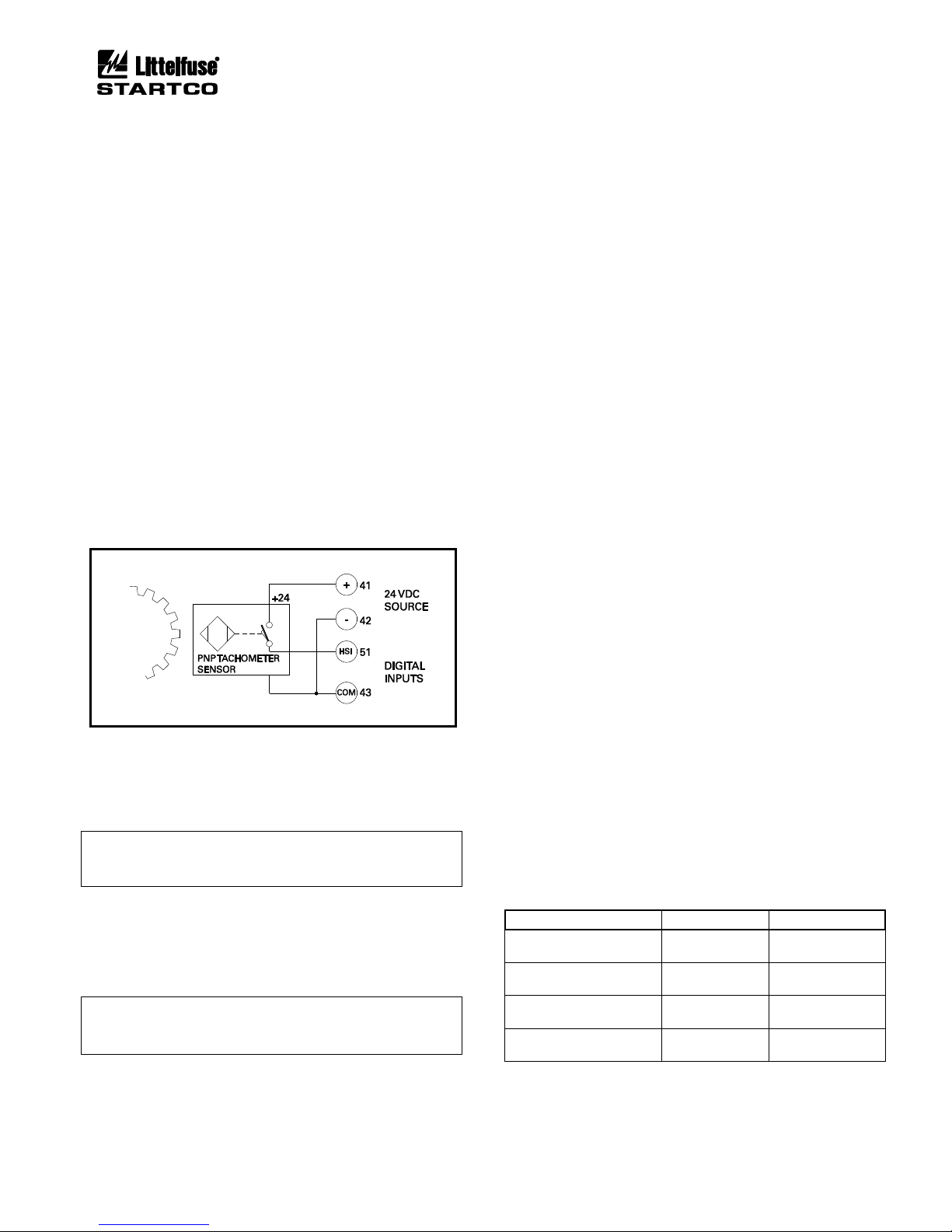
3.2.1.4.4 TACHOMETER INPUT (HSI)
A tachometer sensor can be used to provide motorspeed measurement. Connect a logic-output PNP
tachometer as shown in Fig. 3.7.
FIGURE 3.7 Digital Tachometer Input (HSI).
3.2.1.5 ANALOG INPUT (AN IN)
The analog input (terminal 52 and 53) is a 4-20-mA
current input with a 100-Ω input impedance.
NOTE: The analog input is referenced to an internal
supply with 100-kΩ resistors. Maximum common-mode
voltage is ± 5 Vdc with respect to MPS-CTU terminal 4.
3.2.1.6 ANALOG OUTPUT (AN OUT)
The analog output is a self-powered current-source
output. The current source output is the “+” (terminal 39)
and the common is “−” (terminal 40).
NOTE: The analog output (terminal 40) is internally
referenced to the 24-Vdc source (terminal 42) and the I/O
supply (terminal 56).
3.2.1.7 PTC INPUT
Terminals 54 and 55 are provided for PTC overtemperature protection. See Section 9 for specifications.
3.2.1.8 IRIG-B INPUT
Terminals 61 and 62 are used for an IRIG-B time-code
signal. When an IRIG-B signal is detected, the real-time
clock (RTC) synchronizes with it. The user must set the
MPS date value because the IRIG-B day-of-the-year
parameter is not supported.
If the time-code generator does not have a local-time
adjustment, the IRIG Offset set points can be used to
adjust the hour and minute values so that the MPS will
read local time.
3.2.1.9 I/O MODULE COMMUNICATION
The I/O module communications interface (terminals
56 through 60) is used to support optional modules. The
connector labeled Operator Interface on the MPS-CTU
top panel is in parallel with terminals 50 to 56. It is used
for direct MPS-OPI mounting. See Section 2.3.
I/O module communication is based on the 2-wire
multi-drop RS-485 standard. Overall line length must not
exceed 1.2 km (4,000’). For line lengths exceeding
10 m (33’), 150-Ω terminations are required at the cable
ends. See Fig. 3.9.
3.2.1.10 RS-485 NETWORK COMMUNICATIONS
Terminals 35, 36, and 37 are used for the standard
RS-485 interface. See Section 4.2.15.
3.2.2 MPS-OPI CONNECTIONS AND ADDRESS SELECTION
Connect the MPS-OPI to the MPS-CTU using shielded
cable (Belden® 3124A or equivalent). The 24-Vdc supply
for the MPS-OPI is provided by the MPS-CTU. The
cable shield must be connected at both ends so that
MPS-OPI transient protection is operational. See Fig. 3.9.
The MPS-OPI has two switches to select its network
address. See Figs. 2.2 and 3.8. Up to three MPS-OPI
modules can be connected to the I/O MODULE bus, and
each active OPI must have a unique address. If one OPI
is used, address 1 must be used. If two OPI's are used,
addresses 1 and 2 must be used. If three OPI's are used,
addresses 1, 2, and 3 must be used.
Table 3.1 and Fig. 3.8 shows the addressing selection
format.
TABLE 3.1 MPS-OPI ADDRESS SELECTION
ADDRESS
SWITCH 1
SWITCH 2
0
(Factory Test)
Open
Open
1
(First OPI)
Closed
Open
2
(Second OPI)
Open
Closed
3
(Third OPI)
Closed
Closed
 Loading...