

Page 1
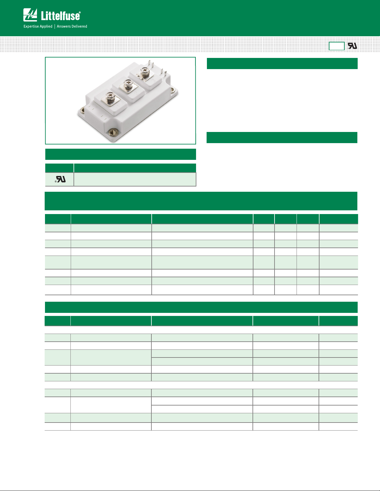
Power Module
1200V IGBT Family
MG12300D-BN2MM Series 300A Dual IGBT
RoHS
Features
• High short circuit
capability,self limiting
short circuit current
3
• IGBT
CHIP(Trench+Field
Stop technology)
• V
with positive
CE(sat)
• Fast switching and short
tail current
• Free wheeling diodes
with fast and soft reverse
recovery
• Low switching losses
temperature coefcient
Applications
Agency Approvals
AGENCY AGENCY FILE NUMBER
E71639
Module Characteristics (T
Symbol Parameters Test Conditions Min Typ Max Unit
T
Vj max)
T
Vj op
T
stg
V
isol
CTI Comparative Tracking Index
Torque Module-to-Sink Recommended (M6) 3 5 N·m
Torque Module Electrodes Recommended (M6) 2.5 5 N·m
Weight 320 g
Max. Junction Temperature 150 °C
Operating Temperature -40 125 °C
Storage Temperature -40 125 °C
Insulation Test Voltage AC, t=1min 3000 V
= 25°C, unless otherwise specified)
C
Module case exposed to 0.1% ammonium
chloride solution per UL and IEC standards
• Inverter
• Converter
350 V
• Motor drives
• SMPS and UPS
• Welder
• Induction Heating
Absolute Maximum Ratings (T
= 25°C, unless otherwise specified)
C
Symbol Parameters Test Conditions Values Unit
IGBT
V
CES
V
GES
I
C
I
CM
P
tot
Collector - Emitter Voltage TVj=25°C 120 0 V
Gate - Emitter Voltage ±20 V
=25°C 480 A
T
DC Collector Current
C
T
=80°C 300 A
C
Repetitive Peak Collector Current tp=1ms 600 A
Power Dissipation Per IGBT 1450 W
Diode
V
RRM
I
F(AV)
I
FRM
2
I
t TVj =125°C, t=10ms, VR=0V 18000 A2s
Life Support Note:
Not Intended for Use in Life Support or Life Saving Applications
The products shown herein are not designed for use in life sustaining or life saving
applications unless otherwise expressly indicated.
MG12300D-BN2MM
Repetitive Reverse Voltage TVj=25°C 120 0 V
=25°C 480
T
Average Forward Current
C
=80°C 300
T
C
Repetitive Peak Forward Current tp=1ms 600 A
1
Specifications are subject to change without notice.
©2013 Littelfuse, Inc
A
A
Revised:08/06/13
Page 2

Power Module
1200V IGBT Family
Electrical and Thermal Specifications (T
= 25°C, unless otherwise specified)
C
Symbol Parameters Test Conditions Min Typ Max Unit
IGBT
V
V
I
I
R
Q
C
C
t
t
t
t
E
E
I
R
GE(th)
CE(sat)
CES
GES
Gint
ge
ies
res
d(on)
r
d(off)
f
on
off
SC
thJC
Gate - Emitter Threshold Voltage VCE=VGE, IC=12mA 5.0 5.8 6.5 V
I
Collector - Emitter
Saturation Voltage
Collector Leakage Current
=300A, VGE=15V, TVj=25°C 1. 7 V
C
I
=300A, VGE=15V, TVj=125°C 1. 9 V
C
=1200V, VGE=0V, TVj=25°C 1 mA
V
CE
V
=1200V, VGE=0V, TVj=125°C 5 mA
CE
Gate Leakage Current VCE=0V,VGE=±15V, TVj=125°C -400 400 μA
Intergrated Gate Resistor 2.5 Ω
Gate Charge VCE=600V, IC=300A , VGE=±15V 2.8 μC
Input Capacitance
V
=25V, VGE=0V, f =1MHz
Reverse Transfer Capacitance 0.85 nF
Turn - on Delay Time
Rise Time
Turn - off Delay Time
Fall Time
Turn - on Energy
Turn - off Energy
Short Circuit Current
CE
=600V
V
CC
IC=300A
RG =2.4Ω
VGE=±15V
Inductive Load
≤10μS , VGE=15V
t
psc
T
=125°C,VCC=900V
Vj
T
=25°C 160 ns
Vj
T
=125°C 170 ns
Vj
=25°C 40 ns
T
Vj
T
=125°C 45 ns
Vj
=25°C 450 ns
T
Vj
T
=125°C 520 ns
Vj
=25°C 10 0 ns
T
Vj
T
=125°C 160 ns
Vj
=25°C 16.5 mJ
T
Vj
T
=125°C 25 mJ
Vj
=25°C 24.5 mJ
T
Vj
T
=125°C 37 mJ
Vj
Junction-to-Case Thermal
Resistance (Per IGBT)
21 nF
120 0 A
0.085 K/W
Diode
=300A , VGE=0V, TVj =25°C 1.65 V
I
V
I
Q
E
R
RRM
F
rr
rec
thJCD
Forward Voltage
Max. Reverse Recovery Current IF=300A , VR=600V 270 A
Reverse Recovery Charge diF/dt=-6000A/μs 56 μC
Reverse Recovery Energy TVj=125°C 26 mJ
Junction-to-Case Thermal
Resistance (Per Diode)
F
I
=300A , VGE=0V, TVj =125°C 1.65 V
F
0.15 K/W
MG12300D-BN2MM
2
Specifications are subject to change without notice.
©2013 Littelfuse, Inc
Revised:08/06/13
Page 3

Power Module
I
C
(A)
VCE˄V˅
T
Vj
=125°C
T
Vj
=25°C
600
500
200
100
0
0
0.5
1.0 1.5
2.0 2.5
V
GE
=15V
3.0
300
400
V
GE=19V
V
GE=17V
V
GE=15V
V
GE=13V
V
GE=11V
V
GE=9V
1200V IGBT Family
Figure 1: Typical Output Characteristics
Figure 2: Typical Output Characteristics
Figure 3: Typical Transfer characteristics Figure 4: Switching Energy vs. Gate Resistor
Figure 5: Switching Energy vs. Collector Current Figure 6: Reverse Biased Safe Operating Area
3
Specifications are subject to change without notice.
MG12300D-BN2MM
©2013 Littelfuse, Inc
Revised:08/06/13
Page 4

Power Module
1200V IGBT Family
Figure 7: Diode Forward Characteristics Figure 8: Switching Energy vs. Gate Resistort
Figure 9: Switching Energy vs. Forward Current Figure 10: Transient Thermal Impedance
MG12300D-BN2MM
4
Specifications are subject to change without notice.
©2013 Littelfuse, Inc
Revised:08/06/13
Page 5

Power Module
PRODUCT TYPE
M: Power Module
MODULE TYPE
G: IGBT
CIRCUIT TYPE
WAFER TYPE
PACKAGE TYPE
MG12300D-BN2MM
VOLTAGE RATING
CURRENT RATING
ASSEMBLY SITE
12: 1200V
300: 300A
D: Package D
B: 2x(IGBT+FWD)
1200V IGBT Family
Dimensions-Package D
Circuit Diagram and Pin Assignment
Packing Options
Part Number Marking Weight Packing Mode M.O.Q
MG12300D-BN2MM MG12300D-BN2MM 320g Bulk Pack 30
Part Numbering System
Part Marking System
MG12300D-BN2MM
5
Specifications are subject to change without notice.
©2013 Littelfuse, Inc
Revised:08/06/13
 Loading...