

Page 1
Power Module
600V IGBT Family
MG06400D-BN1MM Series 400A Dual IGBT
RoHS
Features
• Ultra low loss
• High ruggedness
• Positive temperature
coefcient
• High short circuit
capability
Applications
• Motor drives
Agency Approvals
• Inverter
• Converter
AGENCY AGENCY FILE NUMBER
E71639
Module Characteristics (T
Symbol Parameters Test Conditions Min Typ Max Unit
T
Vj max)
T
Vj op
T
STG
V
isol
CTI Comparative Tracking Index
R
thJC
R
thJCD
Torque Module-to-Sink Recommended (M6) 3 5 N·m
Torque Module Electrodes Recommended (M6) 2.5 5 N·m
Weight 310 g
Max. Junction Temperature 150 °C
Operating Temperature
Storage Temperature Range -40 125 °C
Insulation Test Voltage
Junction-to-Case Thermal
Junction-to-Case Thermal
= 25°C, unless otherwise specified)
C
Resistance
Resistance
AC, t=1min 3000
Module case exposed to 0.1% ammonium
chloride solution per UL and IEC standards
Per IGBT
Per Inverse Diode
-40
350 V
• SMPS and UPS
• Welder
• Induction Heating
150 °C
0.09
0.15 K/W
V
K/W
Absolute Maximum Ratings (T
= 25°C, unless otherwise specified)
C
Symbol Parameters Test Conditions Values Unit
IGBT
V
V
I
I
P
CES
GES
C
Cpuls
tot
Collector - Emitter Voltage 600 V
Gate - Emitter Voltage ±20 V
=25°C 460 A
T
DC Collector Current
Pulsed Collector Current
C
T
=50°C 400 A
C
=25°C, tp=1ms 920 A
T
C
T
=50°C, tp=1ms 800 A
C
Power Dissipation Per IGBT 140 0 W
Free-Wheeling Diode
V
RRM
I
F(AV)
I
F(RMS)
I
FSM
Life Support Note:
Not Intended for Use in Life Support or Life Saving Applications
The products shown herein are not designed for use in life sustaining or life saving
applications unless otherwise expressly indicated.
MG06400D-BN1MM
Repetitive Reverse Voltage 600 V
=25°C 400
T
Average Forward Current
C
=50°C 320
T
C
RMS Forward Current 570 A
=45°C, t=10ms, Sine 120 0 A
Non-Repetitive Surge
Forward Current
T
Vj
T
=45°C, t=8.3ms, Sine 1320 A
Vj
1
Specifications are subject to change without notice.
©2013 Littelfuse, Inc
A
A
Revised:08/06/13
Page 2

Power Module
600V IGBT Family
Electrical Characteristics (T
= 25°C, unless otherwise specified)
C
Symbol Parameters Test Conditions Min Typ Max Unit
IGBT
V
V
I
CES
I
GES
R
Q
C
C
C
t
t
t
t
E
E
GE(th)
CE(sat)
Gint
ge
ies
oes
res
d(on)
r
d(off)
f
on
off
Gate - Emitter Threshold Voltage VCE=VGE, IC=8mA 4.5 5.5 6.5 V
I
Collector - Emitter
Saturation Voltage
Collector Leakage Current
=400A, VGE=15V, TVj=25°C 1.95 2.45 V
c
I
=400A, VGE=15V, TVj=125°C 2.2 V
C
=600V, VGE=0V, TVj=25°C 1 mA
V
CE
V
=600V, VGE=0V, TVj=125°C 2 mA
CE
Gate Leakage Current VCE=0V, VGE=±20V 1.2 1.2 μA
Intergrated Gate Resistor 2.5 Ω
Gate Charge VCE=300V, IC=400A , VGE=±15V 1.8 μC
Input Capacitance
Output Capacitance 1. 8 nF
V
=25V, VGE=0V, f =1MHz
CE
18 nF
Reverse Transfer Capacitance 1. 6 nF
=25°C 195 ns
T
Turn - on Delay Time
Rise Time
Turn - off Delay Time
Fall Time
Turn - on Energy
Turn - off Energy
V
=300V
CC
IC=400A
RG =3Ω
VGE=±15V
Inductive Load
Vj
=125°C 220 ns
T
Vj
=25°C 65 ns
T
Vj
T
=125°C 80 ns
Vj
=25°C 295 ns
T
Vj
T
=125°C 350 ns
Vj
=25°C 45 ns
T
Vj
T
=125°C 60 ns
Vj
=25°C 6.5 mJ
T
Vj
T
=125°C 10 mJ
Vj
=25°C 9.5 mJ
T
Vj
T
=125°C 14.5 mJ
Vj
Free-Wheeling Diode
=400A , VGE=0V,TVj =125°C 1.25 1.6 V
I
V
T
I
Q
RRM
F
rr
Forward Voltage
Reverse Recovery Time IF=400A , VR=300V 249 ns
Reverse Recovery Charge diF/dt=-2000A/μs 214 A
rr
Reverse Recovery Charge TJ =125°C 31 μC
F
I
=400A , VGE=0V, TVj =125°C 1. 2 V
F
MG06400D-BN1MM
2
Specifications are subject to change without notice.
©2013 Littelfuse, Inc
Revised:08/06/13
Page 3

Power Module
820
700
560
I
C
(A)
T
Vj
=25°C
420
V
CE(sat)
˄V˅
T
Vj
=125°C
280
140
0
0 1 1.5 2.5 3.5
2 3
0.5
36
E
on
E
off
(mJ)
30
24
18
12
6
0 120 360
I
C
˄A˅
VCC=300V
R
G
=3ohm
V
GE
=±15V
T
Vj
=125°C
E
on
E
off
840720 600
480 240
0
36
30
12
24
6
0
03
6
912 15
18
E
on
E
off
(mJ)
E
on
E
off
RG˄ohm˅
21
VCC=300V
I
C
=400A
V
GE
=±15V
T
Vj
=125°C
18
t
(ns)
100
0 80 240
I
C
˄A˅
VCC=300V
R
G
=3ohm
V
GE
=±15V
T
Vj
=125°C
t
d(off)
t
f
t
r
t
d(on)
560480 400
320 160
10
1000
t
d(on)
t
d(off)
1000
10
VCC=300V
I
C
=400A
V
GE
=±15V
T
Vj
=125°C
t
(ns)
t
r
t
f
100
02
4
68 10
12
R
G
˄ohm˅
14
820
VCE=20V
700
560
I
C
(A)
420
280
T
Vj
=125°C
T
Vj
=25°C
140
0
0
V
GE
˄V˅
142468 10 12
600V IGBT Family
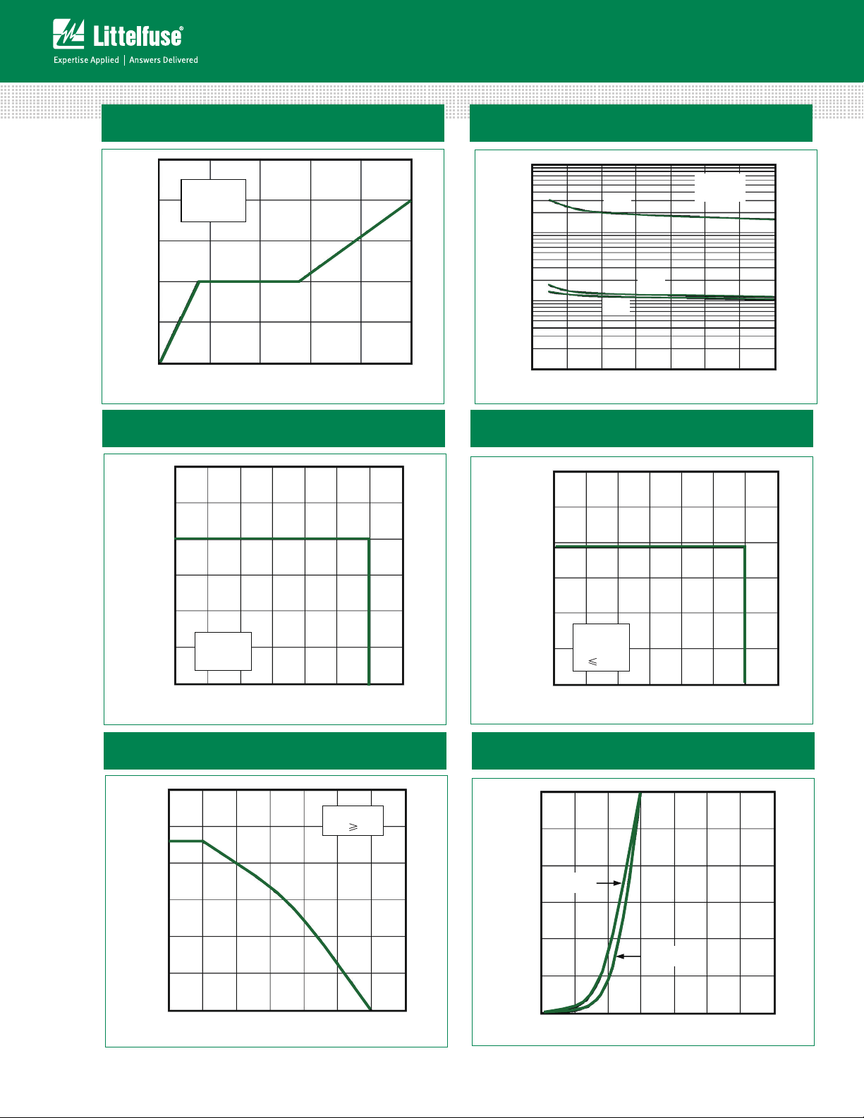
Figure 1: Typical Output Characteristics
Figure 3: Switching Energy vs. Collector Current
Figure 2: Typical Transfer Characteristics
Figure 4: Switching Energy vs. Gate Resistor
Figure 5: Switching Times vs. Collector Current Figure 6: Switching Times vs. Gate Resistor
MG06400D-BN1MM
3
Specifications are subject to change without notice.
©2013 Littelfuse, Inc
Revised:08/06/13
Page 4
Power Module
V
GE
(V)
Qg˄nC˅
0
0
20
25
10
15
5
400
800
1200
1600
2000
VCC=300V
I
C
=400A
T
Vj
=25°C
C (nF)
VCE˄V˅
30 25 20 15
V
GE
=0V
f=1MHz
C
ies
C
res
0.1
1
0
510
C
oes
100
10
35
00 100 300
V
CE
˄V˅
700
200 400
500 600
I
C
p
uls
(
A
)
T
Vj
=150°C
T
C
=25°C
V
GE
=15V
1000
800
600
400
200
1200
0
0100
200
300 400 500
600
V
CE
˄V˅
700
2000
2400
1600
120
I
0
800
400
Csc
(A)
T
Vj
=150°C
T
C
=25°C
V
GE
=15V
t
sc
İ10µs
TC Case Temperature(°C)
I
C
(
A
)
T
Vj
=150°C
V
GE
ı15V
0
25
0
300
200
100
500
400
50 75
125
100
150
600
175
T
Vj
=125°C
T
Vj
=25°C
820
700
560
420
I
F
(A)
280
140
0
V
˄V˅
03 3.5
2.5
2.0
1.51.0
0.5
600V IGBT Family
Figure 7: Diode Forward Characteristics
Figure 9: Reverse Biased Safe Operating Area
Figure 8: Typical Capacitances vs. V
CE
Figure 10: Short Circuit Safe Operating Area
Figure 11: Rated Current vs. T
MG06400D-BN1MM
C
Figure12: Diode Forward Characteristics
4
Specifications are subject to change without notice.
©2013 Littelfuse, Inc
Revised:08/06/13
Page 5
Power Module
10
-1
10
-2
10
-3
1
10
-1
10
-2
10
-3
10
-4
10
-4
Duty
0.5
0.2
0.1
0.05
Single Pulse
Z
thJC
(K/W)
1
Rectangular Pulse Duration (seconds)
10
-4
10
-4
10
-3
10
-3
10
-2
10
-2
10
-1
10
-1
1
1
Duty
0.5
0.2
0.1
0.05
Single Pulse
Z
thJC
(K/W)
Rectangular Pulse Duration (seconds)
600V IGBT Family
Figure 13: Transient Thermal Impedance of IGBT
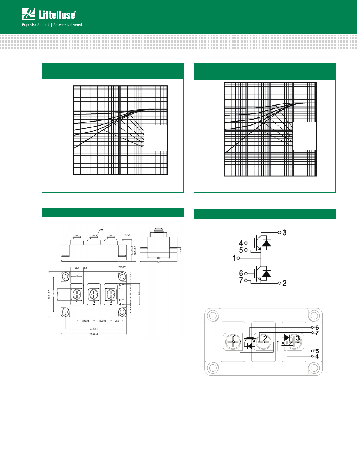
Dimensions-Package D
Figure 14:Transient Thermal Impedance of Diode
Circuit Diagram and Pin Assignment
MG06400D-BN1MM
5
Specifications are subject to change without notice.
©2013 Littelfuse, Inc
Revised:08/06/13
Page 6
Power Module
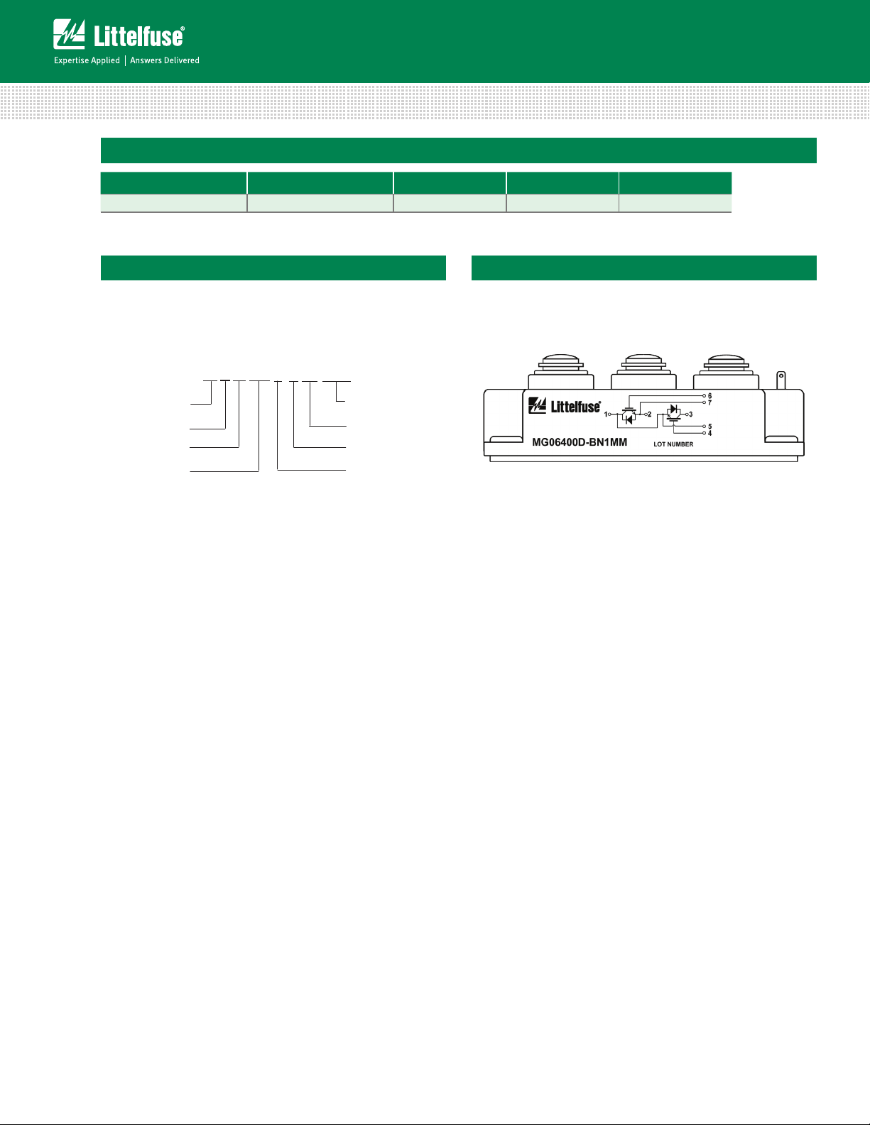
PRODUCT TYPE
M: Power Module
MODULE TYPE
G: IGBT
CIRCUIT TYPE
WAFER TYPE
PACKAGE TYPE
MG06400D-BN1MM
VOLTAGE RATING
CURRENT RATING
ASSEMBLY SITE
06: 600V
400: 400A
D: Package D
B: 2x(IGBT+FWD)
600V IGBT Family
Packing Options
Part Number Marking Weight Packing Mode M.O.Q
MG06400D-BN1MM MG0640 0D-BN1MM 310g Bulk Pack 30
Part Numbering System
Part Marking System
MG06400D-BN1MM
6
Specifications are subject to change without notice.
©2013 Littelfuse, Inc
Revised:08/06/13
 Loading...