

Littelfuse menber's Series Mounting Instructions
A LITTELFUSE BRAND
STACCABATTERIE BIPOLARE 250/350/500A
DUAL POLE BATTERY MASTER SWITCH 250/350/500A
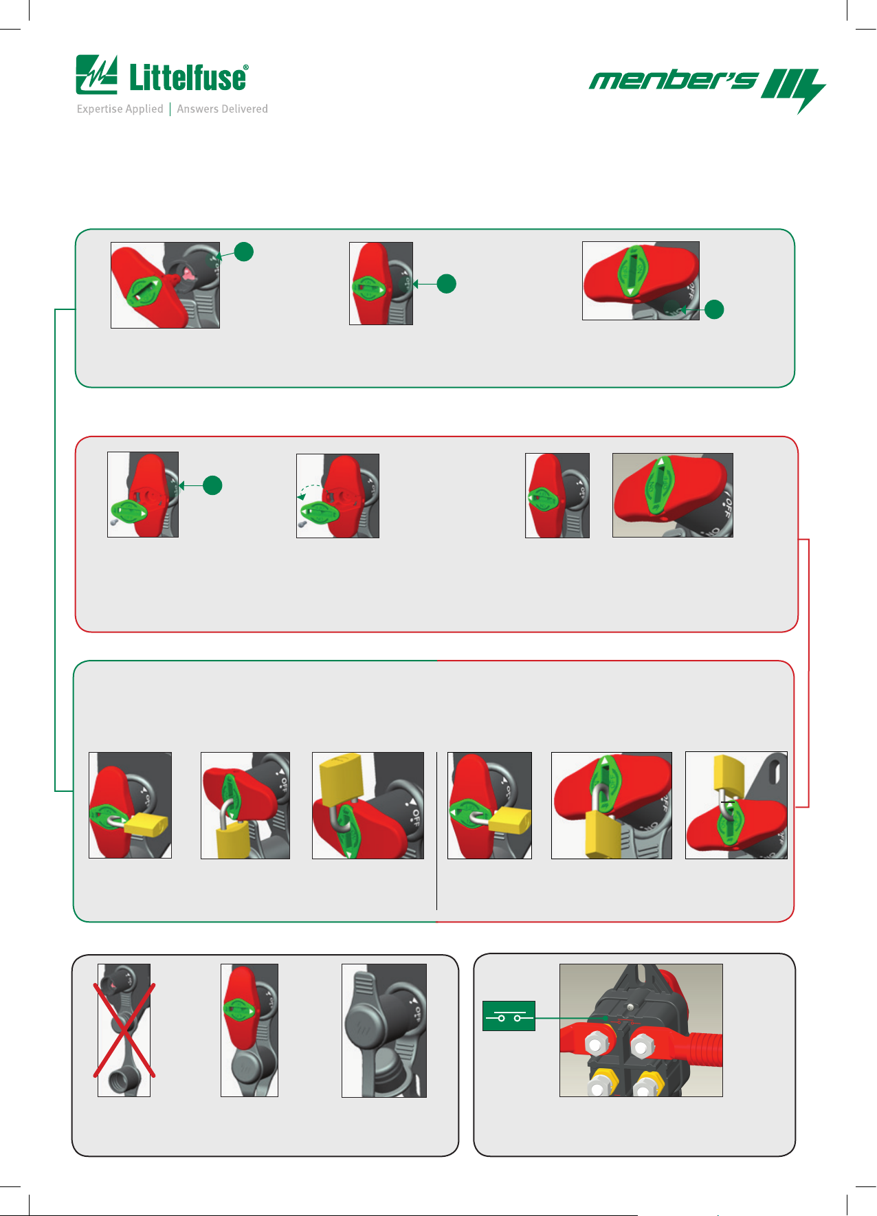
MONTAGGIO MANIGLIA ESTRAIBILE / MOUNTING REMOVABLE HANDLE
▼
OFF
ON
A1
Inserimento chiave
Handle mounting position
A2
Posizionare chiave in OFF
Set handle to OFF
A3
Posizionare chiave in ON
Set handle to ON
SMARTKEY: TRASFORMAZIONE IN MANIGLIA NON ESTRAIBILE
HOW TO HAVE A NOT REMOVABLE HANDLE
OFF
B3
Da posizione OFF svitare ed estrarre
l’inserto verde
In OFF position unscrew and extract
the green insert
USO DEL LUCCHETTO / HOW TO USE THE PADLOCK
1. Si può luchettare la maniglia sia nella posizione ON che in quella OFF
2. Lucchetto fissato: si può scegliere di non luchettare la maniglia ma lasciare il lucchetto su di essa nella posizione “fissaggio lucchetto alla maniglia
1. You can lock the handle either to ON or OFF position
2. Parking the padlock: you can choose not to lock the handle but leave the padlock on the handle in the padlock parking position
CON CHIAVE ESTRAIBILE / WITH REMOVABLE HANDLE
B4
Ruotare l’inserto verde di 180° e fissarlo
alla maniglia
Rotate the green insert 180° and screw it to
the handle
CON CHIAVE FISSA / WITH FIXED HANDLE
B5
Ora la maniglia è non rimovibile e può essere
posizionata in ON oppure OFF
Now the handle is no longer removable
and can be set in ON or OFF
A4
Lucchettato in OFF
Lock in OFF
SALVA-SPORCO / DIRT-PROTECTION
C1
Cappuccio aperto
Opened cap
A5
Lucchettato in ON
Lock in ON
C2
Cappuccio chiuso
Closed cap
A6
Lucchetto fissato
Padlock parked
C3
Cappuccio montato
Mounted cap
B6
Lucchettato in OFF
Lock in OFF
CIRCUITO ELETTRICO / ELECTRICAL CIRCUIT
B7
Lucchettato in ON
Lock in ON
D1
Orientamento staccabatteria
Battery disconnector orientation
B8
Lucchetto fissato
Padlock parked
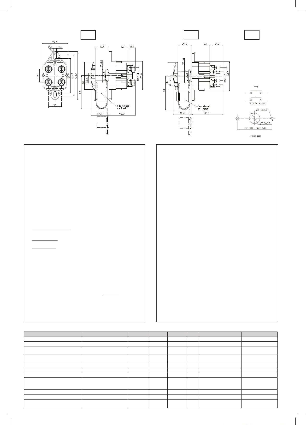
ISTRUZIONI DI MONTAGGIO MOUNTING INSTRUCTION
08084000
08084200 08084100
250A
1) Fissaggio dello staccabatterie
Utilizzare viti M8, serrate a 8 +-1.5 Nm, con rondelle piane diam.esterno 18
mm e rondelle elastiche antisvitamento.
2) Montaggio maniglia
Inserire la manigli a con inserto verde allineando i riferimenti triangolari (fig.A1)
3) Maniglia non estraibile
Per rendere la maniglia non estraibile mediante rotazione dell’inserto verde
procedere come segue :
3a) inserire la maniglia completa di inserto verde e portarla in una delle due
posizioni stabili (OFF o ON) (fig.B3)
3b) svitare la vite fissaggio inserto ed estrarre solo l’inserto lasciando la
maniglia nella propria posizione, ruotare l’inserto di 180°(B4) , riposizionare
l’inserto ruotato in centro alla maniglia, riavvitare la vite di fissaggio
inserto(B4); a questo punto la maniglia potrà ruotare solo di 90°, dalla
posizione ON alla posizione OFF (B5) e viceversa, e non sarà possibile
estrarla.
4) Utilizzo del lucchetto
Il lucchetto, con arco di sezione avente diam. 4,2-4,5 mm, può essere posto :
4a) in posizione di parcheggio: il lucchetto in posizione contrapposta alle
scritte ON e OFF impedisce l’estrazione maniglia ma permettere l’apertura e
chiusura dei contatti (A6 e B8)
4b) in posizione OFF : il lucchetto blocca la maniglia in posizione OFF e
impedisce la manovra di chiusura dei contatti (A4-B6)
4c) in posizione ON: il lucchetto blocca la maniglia in posizione ON e
impedisce la manovra di apertura dei contatti (A6-B7)
5) Cappuccio di chiusura in gomma
Quando si estrare la maniglia si deve immediatamente chiudere il foro
ingresso maniglia con il cappuccio in gomma per evitare l’ingresso di liquidi o
polveri all’interno dello staccabatterie (C3) ; quando non viene utilizzato il
cappuccio deve sempre rimanere richiuso su sé stesso per non accumulare
polvere o liquidi che potrebbero poi entrare all’interno del prodotto(C1)
6) Cavi di collegamento
Per limitare le tem perature si devono utilizzare cavi di collegamento con le
sezioni minime e le lunghezze indicate sulla tabella Dati tecnici.
I cavi devono essere fissati ai contatti rispettando l’orientamento dei contatti
(fig.D1) e devono essere adeguatamente fissati al telaio per prevenire
vibrazioni potenzialmente dannose .
7) Limitazioni di impiego dello staccabatterie 500 A
La versione da 500 A può essere utilizzata solo su veicoli di peso lordo
superiore a 35 quintali
1 ) Mounting the battery switch
Use M8 screws , tighten up to 8 Nm + -1.5 , use flat and lock washers of 18
mm external diameter.
2) How to fit the Handle
Insert the handle with green insert , aligning the triangular reference point (
fig.A1 )
3 ) Handle non- removable
To make the handle A NOT REMOVABLE one, you have to rotate the green
insert, proceed as follows:
3a), insert the handle complete with green insert and choose one of two stable
positions (OFF or ON) (pict.B3)
3b) unscrew the green insert and pull it out, leaving the handle in position ,
rotate the insert 180 ° (pict. B4), put the rotated insert in the center of the
handle , tighten the screw insert (pict. B4) at this point the handle can rotate
only 90 °, in ON or OFF position (pict. B5 ) and vice versa.
4) Use the lock
The padlock with arc section having diam. 4.2 to 4.5 mm, can be placed:
4a) padlock parking position : the padlock fitted in position opposite to the
written ON and OFF prevents the extraction handle but allows the opening and
closing of the contacts (pict. A6 and B8)
4b) in OFF position: the padlock locks the handle in OFF position and prevents
the closing of the circuit (pict. A4-B6)
4c) in the ON position: the lock locks the handle in the ON position and
prevents the opening of the circuit (pict. A6-B7)
5 ) Protective Cap rubber
When the handle is pulled out you can protect the hole for the handle with the
rubber cap to prevent infiltration of liquids or powders inside the battery switch
(pict. C3 ) when not in use the cap must always be closed on itself to not
accumulate dust or liquids that could then enter into the product (pict. C1)
6) Connecting Cables
To keep the temperature of cables within operating range we recommend to
use the minimum cross-sections and lengths indicated on the Technical details
table .
The cables should be attached to main contacts according orientation of the
contacts (pict D1), the cables should be adequately secured to the vehicle
frame to prevent potential damaging through vibrations .
7 ) Limitations for use of the battery switch 500 A
The version 500 A can be used only on vehicles with a gross weight of more
than 3.500 Kilos
350A
500A
DATI TECNICI
Dati tecnici Technical data 250A 350A 500A Condizioni
Tensione nominale di funzionamento Working tension range 8-32 8-32 8-32 V
Corrente di lavoro Working current 100 250 250 A
Corrente massima continuativa sui
contatti principali
Corrente massima sui contatti
principali di breve durata
Temperatura ambiente di lavoro Operating temperature -30÷+60 -30÷+60 -30÷+60 °C
Temperatura di stoccaggio Storage temperature -40÷+85 -40÷+85 -40÷+85 °C
Grado di protezione alla polvere IP 6K IP 6K IP 6K - Secondo DIN 40050-9 According DIN 40050-9
Grado di protezione ai getti d’acqua Dust protection
Viti di collegamento cavi Connecting screw M10 M12 M12
Coppia serraggio dadi collegamento Nuts screw torque 18±4 22±4 22±4 Nm
(*) Sezioni minime cavi di collegamento Minimum wires cross section 4 x 70 mm2 8 x 120 mm2 8 x 120 mm2
Duty rating 2x250 2x500 2x500 A
Overload 1000 1500 1500 A
IPX5
IPX7
IPX9K
IPX5
IPX7
IPX9K
IPX5
IPX7
IPX9K
Secondo DIN 40050-9 According DIN 40050-9
Lunghezza minima 300 mm e
adeguato ssaggio a telaio
Min.lenght 300 mm and
properlyxed to chassis
COD. 80175200 REV. B - EDIZIONE OTTOBRE 2016
 Loading...