

Page 1
Varistor Products
Axial Lead / Application Specific Varistors > MA Series
RoHS
MA Varistor Series
Agency Approvals
Agency Agency File Number
None
Description
The MA Series of transient surge suppressors are axial
lead Metal Oxide Varistors (MOVs) for use in a wide
variety of board level industrial and commercial electronic
equipment. They are intended to protect components and
signal/data lines from low energy transients where the
small axial lead package is required.
The MA Series is offered with standard ('S' suffix) or
tightened ('B' suffix) clamping voltage.
See MA Series Device Ratings and Specifications Table for
part number and brand information.
Features
t NNEJBNFUFS
disc size
t 4NBMMBYJBMMFBE
package
t 8JEFPQFSBUJOHWPMUBHF
range:
V
V
9V to 264V
M(AC)RMS
13V to 365V
M(DC)
t "WBJMBCMFJOUBQFBOE
reel or bulk packaging
t /PEFSBUJOHVQUP
85ºC ambient
t /FXCMBDLFQPYZPGGFST
improved performance
for high temperature
Lead-free wave
soldering process.
Absolute Maximum Ratings
t'PSSBUJOHTPGJOEJWJEVBMNFNCFSTPGBTFSJFTTFF%FWJDF3BUJOHTBOE4QFDJmDBUJPOTDIBSU
Continuous MA Series Units
Steady State Applied Voltage:
AC Voltage Range (V
DC Voltage Range (V
Transient:
Peak Pulse Current (I
For 8/20μs Current Wave(See Figure 2) 40 to 100 A
Single-Pulse Energy Range
For 2ms Current Square Wave (W
Operating Ambient Temperature Range (T
Storage Temperature Range (T
Temperature Coefficient (αV) of Clamping Voltage (V
Hi-Pot Encapsulation (COATING Isolation Voltage Capability)
Dielectric must withstand indicated DC voltage for one minute per MIL-STD 202, Method 301)
COATING Insulation Resistance 1000 MΩ
CAUTION: Stresses above those listed in “Absolute Maximum Ratings” may cause permanent damage to the device. This is a stress only rating and operation
of the device at these or any other conditions above those indicated in the operational sections of this specification is not implied.
)
TM
) -55 to +125 °C
STG
) 9 to 264 V
M(AC)RMS
) 13 to 365 V
M(DC)
) 0.06 to 1.7 J
) -55 to +85 °C
A
TM
) at Specified Test Current
C
<0.01 %/°C
1000 V
MA Series
©2008 Littelfuse, Inc.
Specifications are subject to change without notice.
Please refer to www.littelfuse.com/series/ma.html for current information.
183
Revision: January 9, 2009
MA Varistor Series
Page 2
Axial Lead / Application Specific Varistors > MA Series
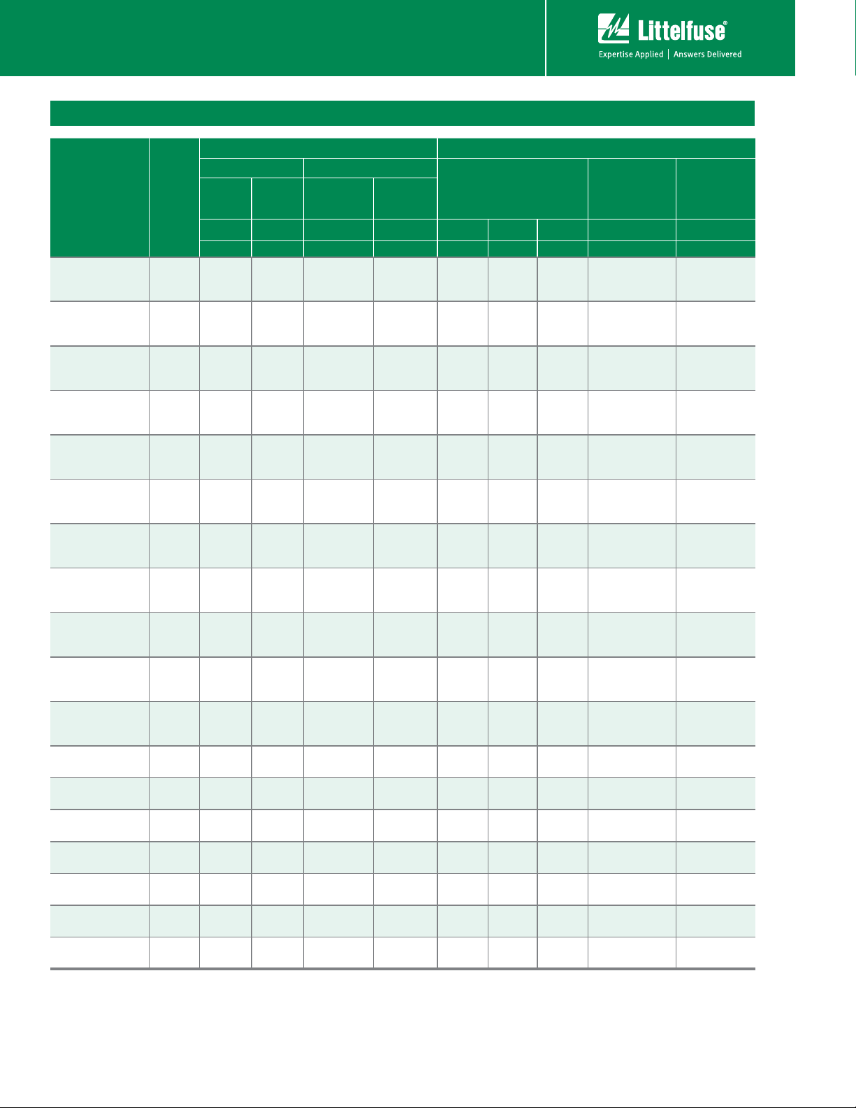
MA Series Ratings & Specifications
Maximum Rating (85°C) Specifications (25°C)
Continuous Transient
Part
Number
V18MA1A
V18MA1A
V18MA1A
V22MA1A
V22MA1B
V22MA1S
V27MA1A
V27MA1B
V27MA1S
V33MA1A
V33MA1B
V33MA1S
V39MA2A
V39MA2B
V39MA2S
V47MA2A
V47MA2B
V47MA2S
V56MA2A
V56MA2B
V56MA2S
V68MA3A
V68MA3B
V68MA3S
V82MA3A
V82MA3B
V82MA3S
V100MA4A
V100MA4B
V100MA4S
V120MA1A
V120MA2B
V120MA2S
V150MA1A
V150MA2B
V180MA1A
V180MA3B
V220MA2A
V220MA4B
V270MA2A
V270MA4B
V330MA2A
V330MA5B
V390MA3A
V390MA6B
V430MA3A
V430MA7B
Brand
(mm)
18A
18B
18C
22A
22B
22S
27A
27B
27S
33A
33B
33S
39A
39B
39S
47A
47B
47S
56A
56B
56S
68A
68B
68S
82A
82B
82S
100
101
102
120
121
122
150
151
180
181
220
221
270
271
330
331
390
391
430
431
V
RMS
V
M(AC)
(V) (V) (J) (A) (V) (V) (V) (A) (pF)
9
10
10
10
14
14
13
17
17
18
20
20
22
25
25
27
30
30
32
35
35
38
40
40
45
50
50
57
60
60
72
75
75
88
92
105
110
132
138
163
171
188
200
234
242
253
264
V
V
M(DC)
13
14
14
15
18
18
19
22
22
23
26
26
28
31
31
34
38
38
40
45
45
48
56
56
60
66
66
72
81
81
97
101
101
121
127
144
152
181
191
224
235
257
274
322
334
349
365
DC
Varistor Products
Energy
(10/1000μs)
WTM I
0.06
0.07
0.06
0.09
0.10
0.09
0.10
0.11
0.10
0.13
0.15
0.14
0.16
0.18
0.17
0.19
0.21
0.19
0.23
0.25
0.23
0.26
0.30
0.27
0.33
0.37
0.34
0.40
0.45
0.42
0.40
0.50
0.46
0.50
0.60
0.60
0.70
0.80
0.90
0.90
1. 0 0
1. 0 0
1. 10
1.20
1.30
1.50
1.70
Peak
Current
(8/20μs)
40
40
40
40
40
40
40
40
40
40
40
40
40
40
40
40
40
40
40
40
40
40
40
40
40
40
40
40
40
40
100
100
100
100
100
100
100
100
100
100
100
100
100
100
100
100
100
Varistor Voltage at 1mA
DC Test Current
Min V
TM
14
15
15
16
19
19
21
24
24
26
29.5
29.5
31
35
35
37
42
42
44
50
50
54
61
61
65
73
73
80
90
90
102
108
108
127
135
153
162
187
198
229
243
280
297
331
351
365
387
N(DC)
18
18
18
22
22
22
27
27
27
33
33
33
39
39
39
47
47
47
56
56
56
68
68
68
82
82
82
100
100
100
120
120
120
150
150
180
180
220
220
270
270
330
330
390
390
430
430
Max Clamping
at 2.0A
Volt V
C
(8/20μs)
Typical
Capacitance
Max VC f = 1MHz
23
21
21
28
26
26
34
31
31
40
36.5
36.5
47
43
43
57
52
52
68
62
62
82
75
75
99
91
91
120
110
110
138
132
132
173
165
207
198
253
242
311
297
380
363
449
429
495
473
49
44
49
55
51
55
67
59
67
73
67
73
86
79
86
99
90
99
117
108
117
138
127
138
163
150
163
200
185
200
220
205
220
255
240
310
290
380
360
460
440
570
540
670
640
74 0
700
550
550
550
410
410
410
370
370
370
300
300
300
250
250
250
210
210
210
180
180
180
150
150
150
120
120
120
100
100
100
40
40
40
32
32
27
27
21
21
17
17
14
14
12
12
11
11
NOTE: Average power dissipation of transients not to exceed 200mW.
MA Varistor Series
184
Revision: January 9, 2009
©2008 Littelfuse, Inc.
Please refer to www.littelfuse.com/series/ma.html for current information.
Specifications are subject to change without notice.
Page 3

Varistor Products
Axial Lead / Application Specific Varistors > MA Series
Power Dissipation Ratings
100
90
80
70
60
50
40
30
20
PERCENT OF RATED VALUE
10
0
-55 50 60 70 80 90 100 110 120 130 140 150
Figure 1
AMBIENT TEMPERATURE (
o
C)
Should transients occur in rapid succession, the average power
dissipation required is simply the energy (watt-seconds) per
pulse times the number of pulses per second. The power so
developed must be within the specifications shown on the
Device Ratings and Specifications table for the specific device.
Furthermore, the operating values need to be derated at high
temperatures as shown above. Because varistors can only
dissipate a relatively small amount of average power they are,
therefore, not suitable for repetitive applications that involve
substantial amounts of average power dissipation.
Peak Pulse Current Test Waveform
100
90
50
PERCENT OF PEAK VALUE
10
O
1
Figure 2
01 = Virtual Origin of Wave
T = Time from 10% to 90% of Peak
T1 = Rise Time = 1.25 x T
T2 = Decay Time
Example - For an 8/20 μs Current Waveform:
8μs = T1 = Rise Time
20μs = T2 = Decay Time
T
T
1
T
2
TIME
Repetitive Surge Capability
V18MA - V100MA
50
1
2
20
10
10
2
10
5
3
10
4
10
2
1
SURGE CURRENT (A)
0.5
INDEFINITE
0.2
0.1
20 100 1,000 10,000
Figure 3
IMPULSE DURATION (μs)
DISC SIZE 3mm
V18MA1A - V100MA4B
5
10
6
10
V120MA1A/S - V430MA3A
100
1
2
50
10
20
2
10
10
5
2
1
SURGE CURRENT (A)
0.5
INDEFINITE
0.2
0.1
20 100 1,000 10,000
IMPULSE DURATION(μs)
DISC SIZE 3mm
V120MA1A - V430MA7B
3
10
4
10
5
10
6
10
Figure 4
NOTE: If pulse ratings are exceeded, a shift of V
+/-10% could result. This type of shift, which normally results in a decrease of V
result in the device not meeting the original published specifications, but it does not
prevent the device from continuing to function, and to provide ample protection.
(at specified current) of more than
N(DC)
N(DC)
, may
MA Series
©2008 Littelfuse, Inc.
Specifications are subject to change without notice.
Please refer to www.littelfuse.com/series/ma.html for current information.
185
Revision: January 9, 2009
MA Varistor Series
Page 4

Axial Lead / Application Specific Varistors > MA Series
Maximum Clamping Voltage
Varistor Products
V18MA1A/S - V100MA4A/S
800
MAX CLAMPING VOLTAGE
DISC SIZE 3mm
600
18 TO 100V
T
= -55oC TO 85oC
400
A
300
200
150
100
80
60
MAXIMUM PEAK VOLTS (V)
40
30
20
-2
10
Figure 5
V120MA1A/S - V430MA3A
4,000
MAX CLAMPING VOLTAGE
DISC SIZE 3mm
120 TO 430V
2,000
T
= -55oC TO 85oC
A
1,500
1,000
800
600
400
MAXIMUM PEAK VOLTS (V)
200
100
-2
10
10
Figure 7
RATING
N(DC)
-1
10
PEAK AMPERES (A)
RATING
N(DC)
-1
PEAK AMPERES (A)
V100MA4A/S
0
10
0
10
V82MA3A/S
V68MA3A/S
V56MA2A/S
V22MA1A/S
V18MA1A/S
V430MA3A
V390MA3A
V330MA2A
V270MA2A
V120MA1A/S
V47MA2A/S
V39MA2A/S
V33MA1A/S
V27MA1A/S
1
10
V220MA2A
V180MA1A
V150MA1A
1
10
V18MA1B - V100MA4B
600
MAX CLAMPING VOLTAGE
500
DISC SIZE 3mm
400
18 TO 100V
T
= -55oC TO 85oC
300
A
200
100
90
80
70
60
50
40
MAXIMUM PEAK VOLTS (V)
30
20
-3
2
10
10
N(DC)
-2
10
RATING
-1
10
PEAK AMPERES (A)
0
10
V33MA1B
V27MA1B
V22MA1B
V18MA1B
1
10
V100MA4B
V82MA3B
V68MA3B
V56MA2B
V47MA2B
V39MA2B
10
2
3
10
Figure 6
V120MA2B - V430MA7B
4,000
MAXIMUM CLAMPING VOLTAGE
DISC SIZE 3mm
3,000
120 TO 430V
2,000
T
= -55oC TO 85oC
A
1,000
900
800
700
600
500
400
300
MAXIMUM PEAK VOLTS (V)
200
100
2
10
-3
10
10
Figure 8
N(DC)
-2
RATING
-1
10
0
10
PEAK AMPERES (A)
V430MA7B
V390MA6B
V330MA5B
V270MA4B
V220MA4B
V180MA3B
V150MA2B
V120MA2B
1
2
10
10
3
10
MA Varistor Series
186
Revision: January 9, 2009
©2008 Littelfuse, Inc.
Please refer to www.littelfuse.com/series/ma.html for current information.
Specifications are subject to change without notice.
Page 5

Wave Solder Profile
TEMPERATURE
(ºC)
TEMPERATURE
(ºC)
Varistor Products
Axial Lead / Application Specific Varistors > MA Series
Non Lead–free Profile
300
250
200
150
100
50
0
Figure 9
00.511.522.533.54
Product Dimensions
LL
(diameter)
Maximum Wave 240C
TIME(MINUTES)
Hb
D
Lead–free Profile
300
250
200
150
100
50
0
Figure 10
00.511.522.533.54
Maximum Wave 260C
TIME(MINUTES)
Physical Specifications
Lead Material Tin–plated Copper clad steel
Soldering
Characteristics
Insulating Material
Solderability per MIL–STD–202,
Method 208E
Cured, flame retardant epoxy polymer
meets UL94V–0 requirements
Symbol
Inches Millimeters
Min Max Min Max
Øb 0.024 0.026 0.61 0.66
ØD 0.118 0.177 3.0 4.5
H 0.177 0.276 4.5 7.0
L 1.740 1.220 27.3 31.0
Typical Weight = 0.5g
Tape and Reel Dimensions
H1 = H2 +/- 0.040”
0.063” max
H1 H2
0.200” +/- 0.02
Device Labeling Marked with LF, voltage and date code
Environmental Specifications
Operating/Storage
Temperature
Passive Aging
Humidity Aging
Thermal Shock
Solvent Resistance MIL–STD–202, Method 215F
-40°C to +85°C
+85°C, 1000 hours
+/-10% typical voltage change
+85°C, 85% RH, 1000 hours
+/-10% typical voltage change
+85°C to -40°C 5 times
+/-10% typical voltage change
Moisture Sensitivity Level 1, J–STD–020C
Part Numbering System
0.080” max
0.240”+/- 0.040
2.062”+/- 0.059
2.681” max
Conforms to EIA Standard RS-296-E
©2008 Littelfuse, Inc.
Specifications are subject to change without notice.
Please refer to www.littelfuse.com/series/ma.html for current information.
Revision: January 9, 2009
VARISTOR
VARISTOR VOLTAGE
(VN at 1mA)
187
V XXX MA XX
SERIES DESIGNATOR
MA: Bulk Pack
MT: Tape and Reel
MA Series
ENERGY/CLAMPING
VOLTAGE VARIANT
MA Varistor Series
 Loading...