

Page 1
Generator Control
Basic
M8100 SERIES
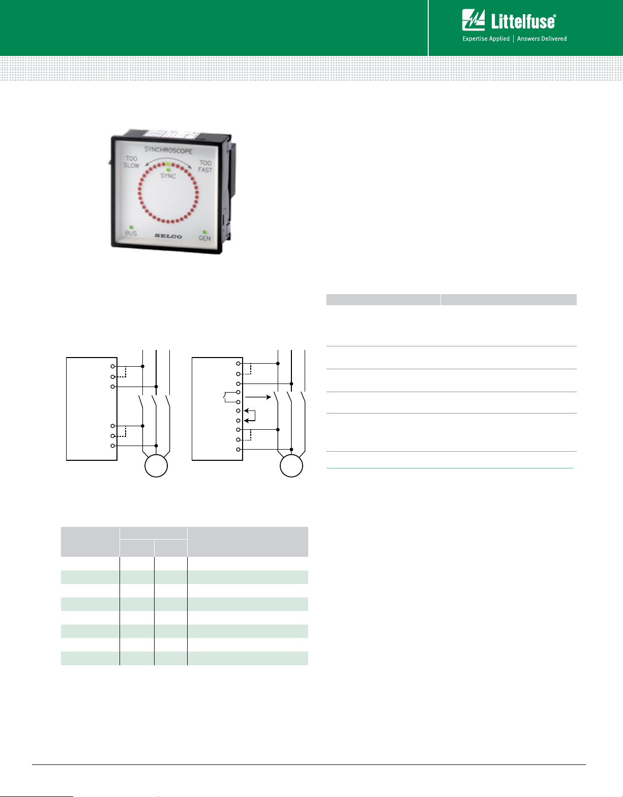
Synchroscope
Simplified Circuit Diagram
M810 0
(Synchroscope)
1
BUS.
2
3
4
GEN.
5
6
L1L2L
G
3
With Check Synchronizer Without Check Synchronizer
M810 0
(Synchroscope)
DEAD BUS
ENABLE
BUS.
GEN.
10
1
2
3
9
4
5
6
CLOSING
7
8
SIGNAL
L1L2L
G
Description
The M8100 Synchroscope provides illuminated indication of
the phase and frequency difference between voltages on
two separate AC systems, e.g. a generator and a busbar. The
M8100 will also indicate whether or not the two systems are
on voltage.
The M8100 is also available in a version with a built-in relay
for automatic closure of the circuit breaker (Synchro Check
Relay). The voltage and frequency are adjusted by the
operator to roughly match the values required, and the unit
will provide a closing signal to the circuit breaker at phase
accordance.
Features & Benefits
FEATURES BENEFITS
High resolution visual
indication by 38 LEDs
3
Available with check
synchronizer relay
Versions available with
dead bus closure
Galvanic isolated inputs
Sturdy casing for flushmount installation, Q96
standard, with protection
class IP52 on the front
Phase and frequency difference; Bus and
generator voltage and phase accordance.
Provides quick, concise status information;
steady viewing of the synchronization process.
Enables use as manual synchronizing unit, or as
auto-synchronizer back-up
Enables use as dead bus monitor in back-up
power installation
Protects the unit against high AC voltage and
currents from the installation including spikes
Easy installation, allowing use in harsh
environments
Ordering Information
ORDERING
NUMBER
M8100.0010 450 V 400 V
M8100.0020 230 V
M8100.0030 480 V 415 V
M8100.0040 110 V 100 V
M8100.0050 450 V 400 V With check synchronizer relay
M8100.0060 230 V With check synchronizer relay
M8100.0070 480 V 415 V With check synchronizer relay
M8100.0080 110 V 100 V With check synchronizer relay
Other vo ltages are available on request .
© 2013 Littelfuse Protection Relays & Controls
www.littelfuse.com/m8100
TERMINALS
1-1
5-7
1-3
6-7
FUNCTION
Specifications
Max. Voltage 660 V
Voltage Range 70 -110%
Consumption 2 x 3 VA max.
Frequency Range 35 -70 Hz
Pull-in/Drop-out
Diff. Frequency ±9 Hz
Operating Temperature –20°C to +70°C
EMC CE according to EN50081-1, EN50082-1,
EN50081-2, EN50082-2
Approvals Certified by major marine classification societies
Burn-in 50 hours before final test
Enclosure Material Flame retardant
Weight 0.7 kg
Dimensions H 96 mm (3.8“); W 96 mm (3.8“); D 80 mm (3.1“)
Panel Cut-out H 92 mm (3.6“); W 92 mm (3.6“)
Unit with check synchronizer relay
Voltage Difference 10-20%
Frequency Difference 0.15-0.3 Hz Combined setting
Phase Difference 6-12°
Dead-bus Delay 1s-5s
Dead-bus Voltage Offset 20%-40%
Min. Generator Voltage
for DB Closure 80% of nominal voltage
Contact Rating AC: 250 V, 1.2 V, 125 VA; DC: 30 V, 1 A, 30 W
}
Rev: 4-A-050313
 Loading...